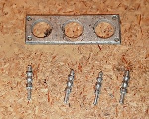
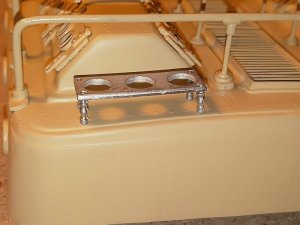
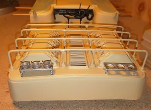
Excellent work, Jhon. Those small details add to the model a charm...
-

Win a Free Custom Engraved Brass Coin!!!
As a way to introduce our brass coins to the community, we will raffle off a free coin during the month of August. Follow link ABOVE for instructions for entering.
-

PRE-ORDER SHIPS IN SCALE TODAY!
The beloved Ships in Scale Magazine is back and charting a new course for 2026!
Discover new skills, new techniques, and new inspirations in every issue.
NOTE THAT OUR FIRST ISSUE WILL BE JAN/FEB 2026
You are using an out of date browser. It may not display this or other websites correctly.
You should upgrade or use an alternative browser.
You should upgrade or use an alternative browser.
Looks like a great kit John. Do you add radio control?
Thanks to all for the comments and the likes,
best regards John,
best regards John,
Looks like a great kit John. Do you add radio control?
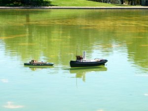
G'day Maarten, yes I will be adding Radio control, I have the motors and the speed controller, also a smoke maker, I have had her on thre pond to make sure everything was watertight, see pics below, she is not fully ballasted yet as I have to add the motors etc and then any extra ballast to bring her down to the water line,
my other little tug which is a river tug, I had to ballast down in the head as when she started to tow the Imara her head would come up,
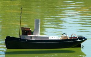
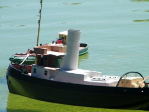
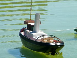
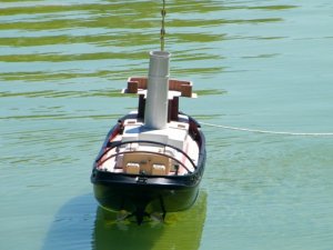
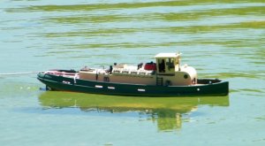
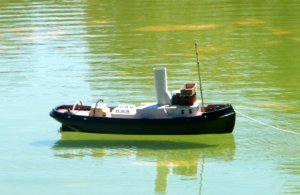
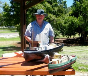
.
Nice pictures, facing the elements where she belongs. Looking forward to the steam generator.
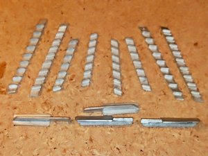
Next up is the ladder ways, this is how they are supplied, and I cut the steps from some 7x2mm stuff i had handy,
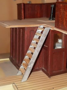
Starboard side assembled,
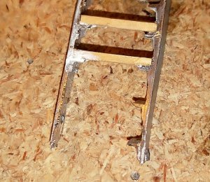
Hower with the smaller ones I had some difficulties as the tread supports were moulded at different heights,
I ended up have to cut the lower two supports on one side so that I could install the treads level,
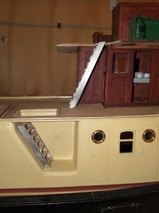
a view of both ladders just sitting in place,
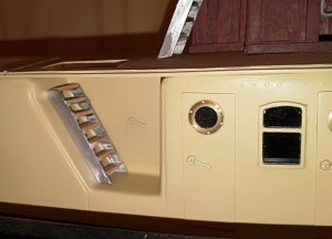
and a view of the lower one which I think could have been a bit longer with maybe one more tread,
.
Great accomplishments thus far, Jhon and both models look really good on the water. As Maarten mentioned we are waiting for 'Smoke on the water, and... (Deep Purple) LOL
Great accomplishments thus far, Jhon and both models look really good on the water. As Maarten mentioned we are waiting for 'Smoke on the water, and... (Deep Purple) LOL
No worries Jim, but you lost me with the Deep Purple part,
best regards John.
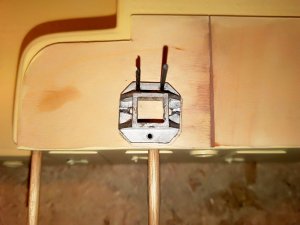
This is the base or footing for one of the davits, Just drilling the holes for securing it to the deck, I have some
1.4m nuts and bolts coming in the post that will secure them in place,
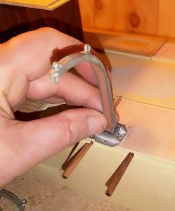
The davits have a pin moulded in at the bottom end which locates in a slot on either side
of the footing, this enables them to pivot, but in practice they will be secured in place,
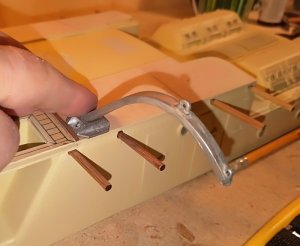
And this shows how far they can be lowered, if you want to show the boat in that position,
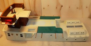
and a view of the superstructure as it is at the moment,
.
here you go JhonNo worries Jim, but you lost me with the Deep Purple part,
Now I get you Jim, must be getting old, ,here you go Jhon
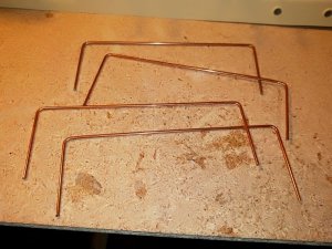
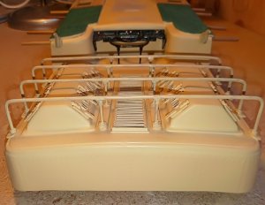
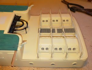
Next up is the protection bars that go over the engine room skylights, they give you straight lengths of steel rod,
which you have to shape to fit as in the pic above,
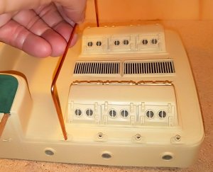
this is where they will be positioned after cutting the legs down to size,
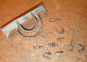
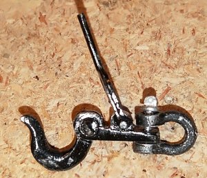
The castings for the towing equipment, they still need a bit if cleaning up and drilling out for the securing bolts
to go through,
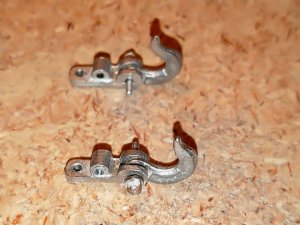
The two hooks assembled with the securing bolts,
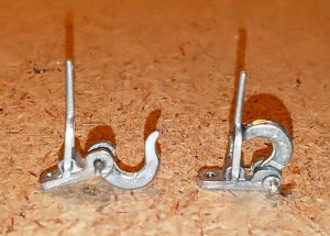
and with the quick release levers attached, I will have one open and the other closed,
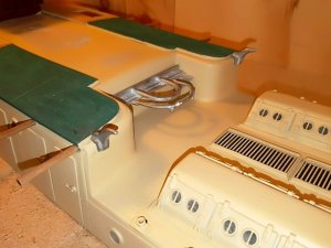
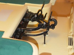
and approximately where the towing gear will sit,
.
Last edited:
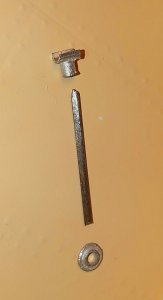
these are the three parts that support the bars that go over
the skylights, you can see in the pic below how they are fitted,
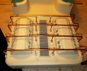
I did have a problem with the thickness of the engine room casing, which was a bit on the thin side,
so I used builders license and glued a strip of 6mm x 2mm pine on top of the casing and then added the
supports,
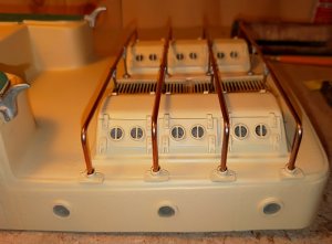
side view,
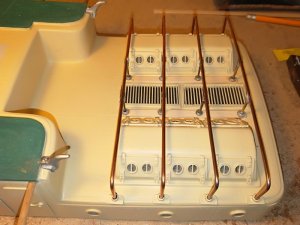
and an overhead view, you can see the strips in place but once painted I think they will blend in OK,
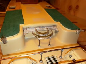
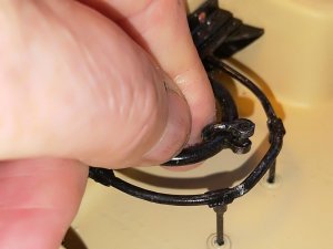
Next up was locating the position of the towing apparatus, the semi circular parts on which the Hooks will sit
had to be level with the top of the protection bars, the unit is not yet glued in place as i have to paint it yet,
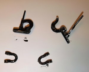
the towing hooks,
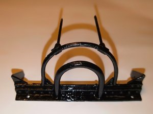
and the main seating piece,
.
Last edited:
Very nice when all the bits and pieces come together. I’m impressed by the detail of the build.
Any painting job is not about me, but I think, I could have something to learn, Jhon.
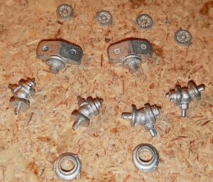
now its on to the fire hydrants, just a little bit of a clean up needed on these, and a little bit of drilling, the two
largest parts at the top of the pic had a short stub on the bottom that is to be glued into a tube, but I decided
to cut the stub off and drill them through to take a piece of brass rod that would go right down through and
into the deck, I though it would be stronger this way,
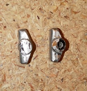
both parts with the stub cut off and one part has been drilled through,
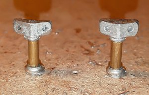
I then sleeved the brass rod with some brass tube to bring it to the right diameter and glued the cast bases in
place, these two hydrants are sitting on the work bench with the brass rod that will go through the deck actually
going through the work bench,
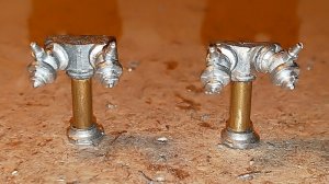
After drilling out the two holes on the top parts and glueing the hydrant connections on,
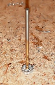
the hand wheels that go on the top are very fragile and they needed to
be drilled out, so I placed them on a piece of wood and taking a drill bit
of the right size I gently tapped the drill bit into the small hole that was
there, then I placed them over a small hole I had drilled through the wood
and kept tapping the drill bit till it went right through, then they just slipped
into place these are very soft and need a lot of care in handling, however
when they are completely glued up they are quite strong,
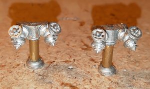
The hand wheels in place,
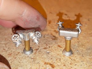
My fingers just to show the size of the pieces,
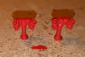
and finally with a coat of red paint, they will dry matt,
.
Any painting job is not about me, but I think, you have something to learn, Jhon.
Don't you like my painting Jim,
best regards John,


