Caldercraft Steam Tug Imara 1/32nd scale by neptune

274.jpg
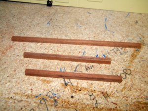
So its onwards and upwards to the frame work that supports the bridge awning, I cut some wood to size
for the support beams, two of each, I had left the beams a little bit longer than needed,


275.jpg
I started on the inside beams first, drilled a hole through the back end and then down through into the railings,
I then placed a piece of brass rod into the hole to hold the beam and then drilled the second hole,


276.jpg
put a second piece of rod into the hole, then marked and drilled the third hole on the bridge front, on the plans
they show these support poles just fixed inside the railings straight onto the deck, i decided to put them into the
railings for more strength,


277.jpg
The first three poles just sitting in place, and I am working out at what height I will fix them,


278.jpg
I then used the same beam to drill the holes on the other side which makes sure they are spaced exactly the same,
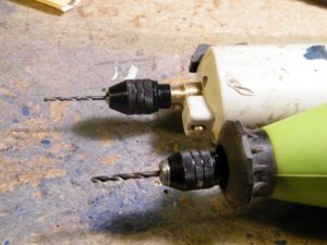
When drilling the holes I used two sizes of brill bit, a pilot size bit and then the exact size bit,


279.jpg
I made sure that both bits were the same length, so that when I cut the brass rod to size all the holes that the
rod went into were the same depth,

280.jpg
 
281.jpg
The two middle supports in place, they look a bit crooked but it is just the camera angle,


282.jpg
another view,


283.jpg
I wanted to have some run off on the awning so I placed the center supports at 70mm and the outside ones
at 65mm, which equates to 7foot in the centre and 6foot 6inches on the outer ones,


284.jpg
head on view,


285.jpg
This shows the round up of the awing, I will be using some stainless steel rod for the cross supports,


.
 
286.jpg
These are the stainless rods and brass eye bolts that i will use for the cross supports,


287.jpg
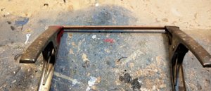
The rod at the front has been bent to the round up needed to sit on the beams with no stress,


288.jpg
I drilled a small hole, .7mm through the beam and placed the eye bolt through it and then bent the end back
up around the side of the beam,


289.jpg
The first cross support in place, this one took a little bit of maneuvering to get it in place, as it not only had
round up but also it had to be bent forwards as well to follow the curve of the bridge front,


290.jpg
a closer view,

.
 
291.jpg
side view of the front support, here again it looks like the far support pole is out of alignment but it isn't,


292.jpg
attaching the second awing support, after it is fixed i will cut it to the right sight size with a cut off disc,
Not a Four Inch one, :D:D:D,


293.jpg
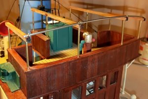
The first two supports in place, there is another one to go in between these two and two smaller ones at the
back where the frame work is narrower,


294.jpg
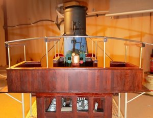
an overall view, I will have to decide whether to leave the suppot poles and cross supports as brass and stainless
steel or paint them, will have to think about it, also whether to attach the actual awing or not,

.
 
Last edited:
296.jpg
With having built up the railings around the water tank there was no way to get from the bridge to the funnel
platform so I built a ladder to go from the deck up to the platform, I cut two pieces of wood to size, making sure
they were long enough to get the ladder out of,


297.jpg
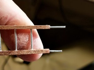
Then I glued each ladder side to the other for one inch at each end to hold them secure while I drilled the
ladder rung holes,


298.jpg
After the glue had dried I then drilled a 1mm hole through both pieces, I had made up a spacer for the ladder rungs,
I put a 1mm piece of rod into the first hole put the spacer against it and drilled the second hole,


299.jpg
Drilling the second hole,


300.jpg
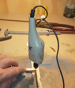
Just in case you thought That I had three hands this is how I took the pic,


301.jpg
The last hole been drilled,


302.jpg
Then after gluing the rods to one side I made another spacer for the width of the ladder
sides, and then glued them in place,


303.jpg
the fiddly bit was drilling the holes up into the ladder sides for the pins to locate into the deck, I have done my
usual thing and cut one pin shorter so I can drill one hole put the long pin in it and mark where the other side
will go,


304.jpg
The ladder in where it will be positioned, I have to trim the top down a bit, and make
and fit two hooks that will secure it to the funnel platform,


305.jpg
The completed ladder with hooks fitted,


306.jpg
and sitting in place, i will have to paint it before gluing in place,


.
 
G'day GdeB, all the overlay decks in the kit came printed on 1mm plywood, Caldercraft made a great job of them,
Best regards John,
 
View attachment 100006
the engine room skylights, there were twelve cast metal skylights included, and you can see the rivet work that is
incorporated in the mouldings, one of the areas that were a bit on the thin side I have covered by plywood which
you can see on the higher part of the deck, once the life boats are in place you will not know the difference, the
small round holders on the superstructure sides are for the bars or rods that go across to keep the towing ropes
off the skylights,


View attachment 100007
Rear view of the small cabin that carries the arches for the towing ropes,


View attachment 100008
Front view,


View attachment 100009
and a view of the after arch, I nailed pins in over a copy of that part of the plan and laminated planks of wood
together to get the shape,


View attachment 100010
looking down on the after deck, you can see the grain pattern on the plywood overlay deck,luckily in this area
there is a large wooden box that has to be constructed to take the Cables and ropes and that will fill most of this
area, even the gratings are cast metal,


View attachment 100011
the towing arches in place, this area has to be lifted off to get access to the speed controller etc when fitted, so I made up a small pin fitted with a chain that goes through the holder and the arch and keeps them secure,


View attachment 100012
close up of the pin in place,


View attachment 100013
and a side on view,


View attachment 100014
the assembled and painted gratings,


.
what diameter did you use for the props?
 
Have a tugship the Smit Nederland for app. 20 Years and I bought the complete Krick set of the Imara at a well known shop in Antwerpen. I am just beginning with opening the box and try to translate the instruction(in German) to a Dutch story. I suppse that GdeB is also starting With the projekt and I amvery impressed by the details in in the Posts of Neptune best Regards Bertus
 
Have a tugship the Smit Nederland for app. 20 Years and I bought the complete Krick set of the Imara at a well known shop in Antwerpen. I am just beginning with opening the box and try to translate the instruction(in German) to a Dutch story. I suppse that GdeB is also starting With the projekt and I amvery impressed by the details in in the Posts of Neptune best Regards Bertus
Thank you for the nice compliment,

best regards John,
 
I am afraid that there no lines printed on the overlaydecks, and I must draw them myself with a pencil !There are also 2 small messing bolts/nuts for the rudder heelst I think to use self inventivity.
 
I must make Some excuses for the overlaydecklines. In the box of the kit the plate was upsidedown so I didnot see the printed linesfor I took out the printed plate of the box. So I am contented about the decklines
 
Very nice work on this kit. Your attention to detailing on the fittings as well as the vessel is excellent.
Jim

Thank you Jim, I didn't reply straightaway as I wasn't sure if you were replying to my tug build or Bertus ships in the last couple of posts,

best regards john.
 
Back
Top