Constellation, the sloop of war c.1856 in 1:36 scale for R/C sailing

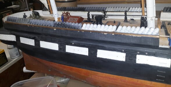
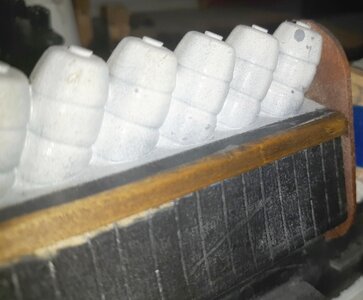
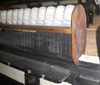
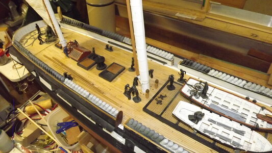
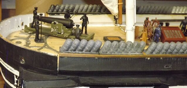
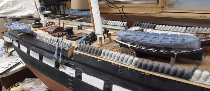
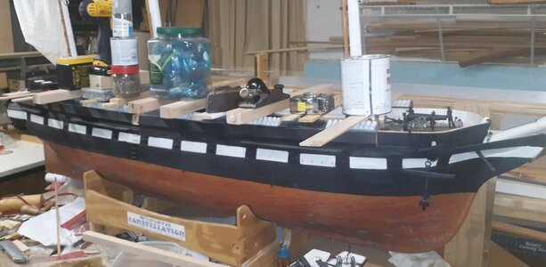
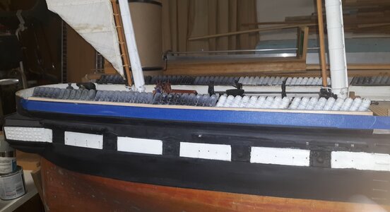
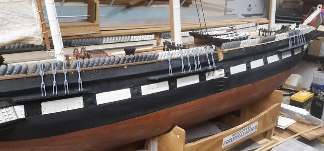
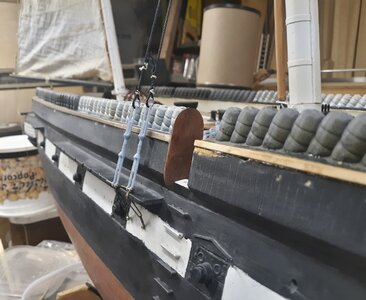
Epoxied the starboard hammocks on the bulwark (portside was done a while back) and ground them down, in-board and out, flush with the bulwark. A strip of 1/16" thick basswood was CAed on to cover the seam and trimmed to the top of the hammock's tray. The In-board seams will get this treatment as well, then there'll be some painting to do.

A variety of weights were used in the gluing-on process

con20220828a.jpg

Blue tape was applied to give the strip an edge to butt to to keep it 1/16" below the seam.
con20220830b.jpgcon20220830c.jpg

Some paint will make a big difference.
con20220830d.jpg con20220830e.jpg
 
I have a project I started nearly 19 years ago, so here's a "build log" for it, but first we need to go back in time and get caught up...

I've built working model boats of all sorts, but most being smallish tended to bob like corks in Baltimore's Inner Harbor where I sailed them. I wanted to build something large that would sail like a boat. I was inspired to action by a model of the Rattlesnake I saw in back-issue of Model Ship Builder magazine, but wasn't sure what boat to build.
View attachment 33453

The hermaphrodite, or "jackass" bark was a favorite rig...
View attachment 33454

But a friend suggested a local boat that had (it's 1999) just gone into dry-dock for restoration; the sloop of war Constellation, which the more I thought about it, the more it sounded like a good idea.
View attachment 33452 Constellation at Naples 1856 by Tomasa deSimone

I won't get into the "controversy" surrounding this boat besides saying, this vessel is not and never was a frigate by any measure. The only people that buy that story also think the world is flat. Her history can be found Here

I made a visit to the National Archives in College Park Maryland and came home with her lines in 1:36 scale, her 1854 sail plan, and several other drawings of the ship, even the lines for her boats.

Rattlesnake was built with extended forms on a baseboard, something like Harold Hahn's method, and that's how I went about building Constellation. The forms were cut from thin plywood paneling pulled out of my house when I remodeled it on a particle-board base, also scrap from the remodel. The keel is 1/2" birch plywood.
View attachment 33455

Before I started planking I came across a book by William Mowell about building the iron frigate Warrior. He battened the forms instead of planking and covered the hull in layers of brown paper packing tape, which he covered in masking tape, made a fiberglass mold from that, and laid up a fiberglass hull in that mold, the original "plug" being destroyed. This seemed like a great idea and a mold would allow me to easily make more than one hull, in fact, I decided to make three; one as the RC model, and two unrigged static models; one to be donated and the other sold, figuring a local Baltimore company would like a 5 foot hull of the Constellation in their lobby, and the money would pay for the whole project.
View attachment 33456

So off on this tangent I went...
View attachment 33457 View attachment 33458 View attachment 33459

The idea was to lay on planking and other details on the "plug" to impart things like plank lines and moldings to the mold, but there were a lot of such details not shown on anything I found at the archives, so I had more research to do. In the mean time we moved to a small farm and the plug was store under plastic in the corner of the barn.
View attachment 56691

The wife and I split up, we sold the farm and the plug went into a storage unit. I bought a house with a workshop in a separate building and in 2009 pulled the old plug out to resume work on it, a decade later.
View attachment 33461 View attachment 33460

Next up: How NOT to build a hull
Hallo @JerryTodd
we wish you all the BEST and a HAPPY BIRTHDAY
Birthday-Cake
 
I've been so caught up with other things over the last year, I've hardly done anything at all to the models. I got some lead shot to make Pride of Baltimore's bulb, glued a section of rail on Constellation's bulwarks, and that's pretty much it.
But...
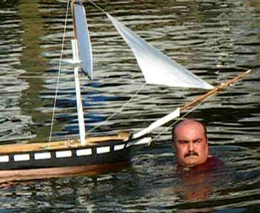
Back when Constellation sailed for the first time in 2011, her battery failed and I had to go swimming to get her. I'm not a good swimmer, so I always take a flotation vest along when I take the models out unless they're in a pool.
con20110710a.png
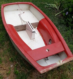
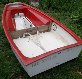
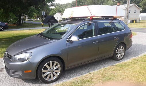
Swimming, even with a flotation vest on, isn't always going to be an option; like when it's cold out. So I figured to get a small pram I could put on top of the car and take down alone. Watching for 7-10 foot dinghies for sale, nothing came up at a price I was willing to pay. I was thinking of building it myself, until just a couple of weeks ago (early June 23) someone a little over an hour away from me was giving away an International Optimist pram for free. I pounced on it like a cat on a bird.
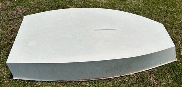
The Red October, (as it's named, which is fitting as I was "hunting" for a boat) is 7'8" (2.4 meters) long, 44" (1.12 meters) wide, and except for some rocker, is as flat as Kansas on the bottom. They race these little boats around the world, I've even seen video of one up on a foil, but this one's life will be much less exciting.
20230620_153218.jpg 20230620_153230.jpg 353507132_5434762659959849_2192933515035267014_n.jpg

It needs some repairs, and a repair of a repair, plus I have a new set of oarlock sockets to install, to go with the oarlocks and oars I got her. It'll need a seat, and probably a skeg to help her track straighter while rowing. she'll get a pad on the transom to mount an electric trolling motor. I even got some proper cross bars for my car's luggage rack instead of using 2x4s. There's no sailing rig, but I'll watch for one, and can make a rudder and dagger board if and when I find it, but I got a chase boat I can car-top by myself now.
20230615_171133.jpg

Oh, and she won't be named Red October. I don't know what I'll name her, IF I name her at all; maybe Catch Them If I Can.
 
Went into the shop to get some tools to work on something, and stopped to snap some pics of the model where it's been sitting, patiently, for me to get back to it.
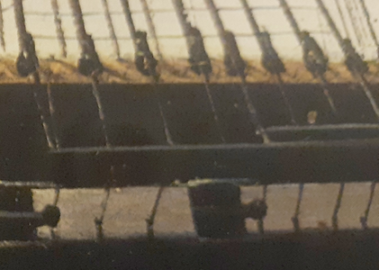
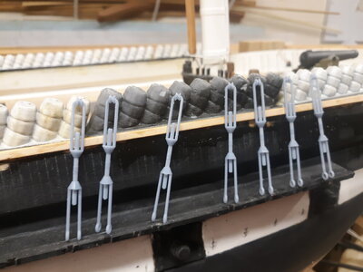
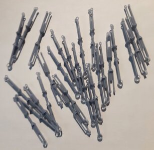
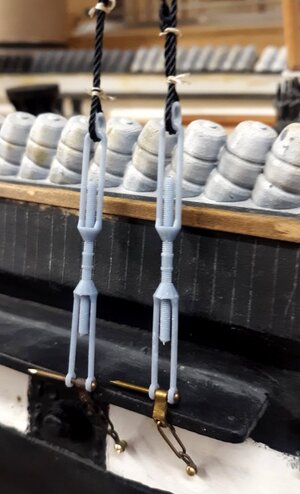
While I haven't done much work on the model itself, besides gluing on a covering board were the hammocks join the bulwark with epoxy that didn't cure properly and needs to be redone; I have been working on a 3D model of her "rigging-screws" (turnbuckles). Yes, I plan to print her rigging-screws, and we'll see how that works out sooner than later, I hope.

con20230806a.jpgcon20230806b.jpgcon20230806c.jpgcon20230806d.jpgcon20230806e.jpg
 
Last edited:
I have a project I started nearly 19 years ago, so here's a "build log" for it, but first we need to go back in time and get caught up...

I've built working model boats of all sorts, but most being smallish tended to bob like corks in Baltimore's Inner Harbor where I sailed them. I wanted to build something large that would sail like a boat. I was inspired to action by a model of the Rattlesnake I saw in back-issue of Model Ship Builder magazine, but wasn't sure what boat to build.
View attachment 33453

The hermaphrodite, or "jackass" bark was a favorite rig...
View attachment 33454

But a friend suggested a local boat that had (it's 1999) just gone into dry-dock for restoration; the sloop of war Constellation, which the more I thought about it, the more it sounded like a good idea.
View attachment 33452 Constellation at Naples 1856 by Tomasa deSimone

I won't get into the "controversy" surrounding this boat besides saying, this vessel is not and never was a frigate by any measure. The only people that buy that story also think the world is flat. Her history can be found Here

I made a visit to the National Archives in College Park Maryland and came home with her lines in 1:36 scale, her 1854 sail plan, and several other drawings of the ship, even the lines for her boats.

Rattlesnake was built with extended forms on a baseboard, something like Harold Hahn's method, and that's how I went about building Constellation. The forms were cut from thin plywood paneling pulled out of my house when I remodeled it on a particle-board base, also scrap from the remodel. The keel is 1/2" birch plywood.
View attachment 33455

Before I started planking I came across a book by William Mowell about building the iron frigate Warrior. He battened the forms instead of planking and covered the hull in layers of brown paper packing tape, which he covered in masking tape, made a fiberglass mold from that, and laid up a fiberglass hull in that mold, the original "plug" being destroyed. This seemed like a great idea and a mold would allow me to easily make more than one hull, in fact, I decided to make three; one as the RC model, and two unrigged static models; one to be donated and the other sold, figuring a local Baltimore company would like a 5 foot hull of the Constellation in their lobby, and the money would pay for the whole project.
View attachment 33456

So off on this tangent I went...
View attachment 33457 View attachment 33458 View attachment 33459

The idea was to lay on planking and other details on the "plug" to impart things like plank lines and moldings to the mold, but there were a lot of such details not shown on anything I found at the archives, so I had more research to do. In the mean time we moved to a small farm and the plug was store under plastic in the corner of the barn.
View attachment 56691

The wife and I split up, we sold the farm and the plug went into a storage unit. I bought a house with a workshop in a separate building and in 2009 pulled the old plug out to resume work on it, a decade later.
View attachment 33461 View attachment 33460

Next up: How NOT to build a hull
Hallo @JerryTodd
we wish you all the BEST and a HAPPY BIRTHDAY
Birthday-Cake
 
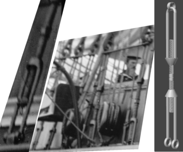
I was about to get back to producing the chainplates, and deadeyes so rigging could actually commence. I was double checking my information when, making a long story short, I realized Constellation's had rigging screws (turnbuckles) her whole life until about 1913 or 14 when she was rerigged with deadeyes and lanyards.chains1856b.png turnbuckles.png

It's near impossible to find good images, or any information on these things, so I made a basic 3D model. I wanted to make them of metal and functional, but finding left-handed taps and dies small, or even left-handed screws and nuts, was hopeless. I decided to 3D print them, non-functional, in one piece. The lower shrouds on this model aren't really structural, as the lower masts as strong enough without them, so they're basically just detail.

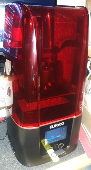
I bought another 3D printer that has a higher resolution and more print volume, while actually costing less than my first printer did. This was it's first print job.
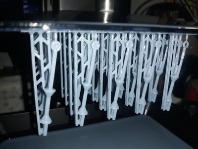
The printer's an Elegoo Mars 3. The 3D model was made in free 3D software called Anim8or. The rigging screws about halfway through the print.
Mars3_20231016j.jpg ringging_screw.png Mars3_20231016k.jpg
20 draft 3D printed rigging-screws about to be cleaned and cured.
con20231016a.jpg

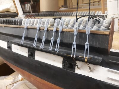
I sat the rigging-screws on the channels, and attached chainplates and a "shroud" to two of them to see how they'll look. I think they'll do the job, but the eyes at the bottoms need to be smaller and the thimble at the top needs to be bigger around, not to mention the more streamlined fairing the conical section should be to the arms (see pic of original on ship).
con20231016d.jpg con20231016e.jpg

con20231016g.jpg
 
I adjusted the 3D model; made the eyes at the bottom smaller, the thimble at the top larger, the screw thicker, and detailed it a bit to look more like the originals. I printed 30 of them which took 3 hours and 20 minutes. Two of them got put on the model under tension to see how they hold up.
ringging_screw.png con20231019a.jpg con20231018b.jpg con20231022d.jpg
 
Last edited:
Moving on, I made the quarter galleries as separate parts that were held on with a screw, but would later be permanently epoxied to the hull as well. They were made from scrap pine and bass sheet.
View attachment 33493 View attachment 33494 View attachment 33495

More pine, cut into strips, was glued in as the deck clamp, and a "sub-deck" of 3/16 luan plywood was cut to fit. It was later cut into 2" wide sections to help it conform to the combined sheer and camber of the deck. Deck beams were 3/4" square pine with the camber cut into them, and notched to fit the deck clamp from underneath. The thinking here was the sub-deck and beams would sandwich the clamps between them. All of this was a bit over-built than it needed to be, but that wasn't a problem.
View attachment 33496 View attachment 33497

Here's a cross-section showing the structure of the deck and it's relation to the hull, as well as how the removable ballast is made and attached.
View attachment 33498

I wasn't going to model the gun-deck or any of the decks below the spar-deck, but I did need a deck below to mount the controls on, and it seemed a good place to step the masts as well. That's were I could use that live oak from the real ship - mast steps!
View attachment 33499 View attachment 33500

This "mechanical deck" was 3/8" plywood sitting on 1" square beams with no sheer or camber. A separate deck is mounted a bit high aft where the rudder servo and mizzen step live. In-between was where the battery would go. I built a box from aircraft plywood the battery would slide upright into, but scrapped that idea and glued in a plywood deck for it to lay down on with Velcro tabs to hold it in place.
View attachment 33501
The paintings that you show here look like they were done by Butterworth. I've seen several that are similar.
 
All the portraits of the ship in Naples are by Thomas deSimone, including one usually said to be the Portsmouth, or some other sloop, but is most definately Constellation
 
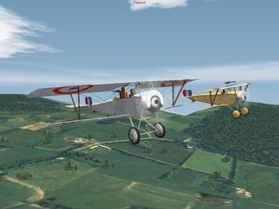
The trick to 3D printing is having something to print, which entails getting, or making a 3D model suitable to be printed. I've used Anim8or software to build digital models since like 1998, making new 3D models of planes for a WWI flight sim.
nieuports.jpg
a couple of Nieuports I "built" in Red Baron 3D around 2000

I'm trying to learn Blender which is much easier, and better, especially for things like ornate carvings as found on the bows and sterns of many ships.

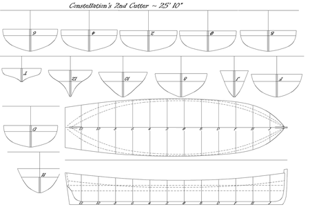
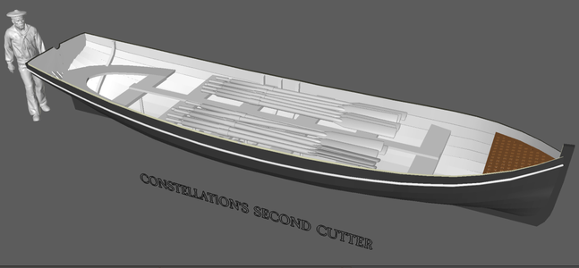
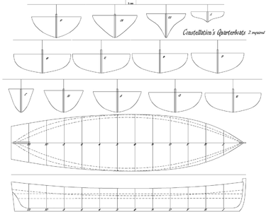
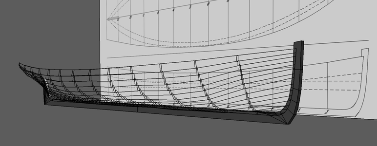
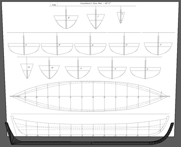
While still trudging along in Anim8or, I picked up the model of Constellation's second cutter that I started a while back. Using the layout for building the cutter in wood that I did some time ago. I printed these plans on full-sheet label paper for all the boats.

2ndcutterpng.png

I drew the starboard side of each form as the outer surface of the clinker planked hull, then placed each one in it's place on the stem/keel/stern-post I already had.
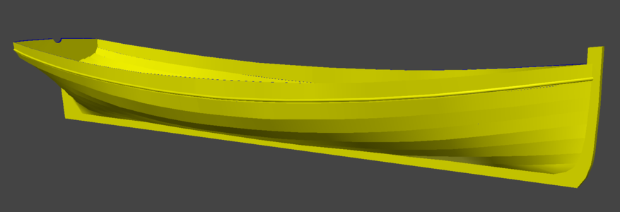
All the points were connected, fore-and-aft, and then filled to make surfaces forming some very clunky clinker planking. Once the starboard side was made, and faired to a point, I mirrored it to make the port sided and see how things were going. This hull was only the outside surface of the model. To be printed, there must also be an inside surface, and all open edges between the outer and inner hull must be closed, ie; everything must be boxed in. Note the blue areas of the model, those are open areas I've yet to close up. The inner hull is a copy of the outer hull with the faces reversed, to face inward, and shrunk slightly, and adjusted a bit, to make a space between them and create about a millimeter of thickness to the planks.
second_cutter3d20231127a.png

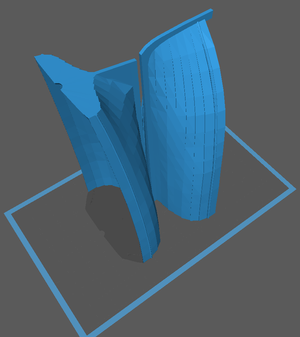
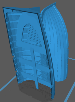
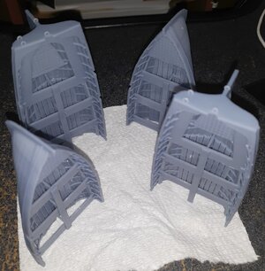
The 25' 10" second cutter is 8.6" in 1:36 scale, which is too long to be printed in my Mars 3 printer, So I divided a copy of the model into two halves, which required closing these new open areas at the cut edge. When printed, the two halves can be welded together with resin and a zap of UV light.

Second_cutter_STL.png

It hasn't been printed yet, as it's not ready; there's still open areas to close, fairing to do, oar notches to install, ribs, grates, seats, floorboards, and all that to do first.
 
Last edited:
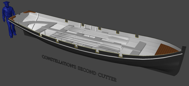
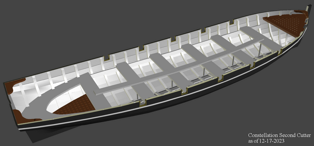
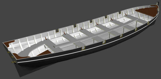
The 2nd cutter's moving along with a grating foredeck, thwarts with supports, an aft seat, and a couple of ribs. The ribs are the more tedious job, and there's like 48 of them in each boat, plus a grating aft, oar notches, and some other construction details.
All the boats will have to be printed in two halves to fit in the printer, as noted in the last post, so things like the oars in the picture, that would span the two halves, will be printed separately
second_cutter3d20231205a.png

Since this seems to be working, so far, I started the other two boats;
The quarterboat (I'll need two of these) that hang in the quarter davits
quarterboat.png quarterboat20231205a.png

and the sternboat (whaleboat), just the keel so far...
sternboat20231205a.png

The quarterboats and sternboat have the highest potential for being damaged since they are outboard on the model. I already had to repair a quarter gallery when it was damaged in a collision. 3D printing them means I can print a replacement if needed.

12/7: Added a little more detail...
second_cutter3d20231207a.png
 
Last edited:
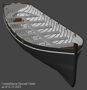
By the 15th of the month, poking away at the model a little each day, I finally got putting in the ribs into something of a process, and had 22 of 25 of them installed.
The seats had all been parallel to the waterline, that put each one at a different height from oar notches, so I set the seats to all be the same height relative to the notches, almost on the line of the sheer.
second_cutter3d20231215.png

The ribs finally done (the last two were cants and took a couple of tried to get right), I redid the forward grating, put in the seat clamps, and a breasthook.
There's floorboards yet to do, and some little details like gudgeons for the rudder, and gudgeon-like hardware for the flag on the transom. The oars from previous pics, the rudder, and any other details will be printed separately. The inner surface of the hull, and the outer surface are not "connected" and there's a gap all around the top edge that has to be sealed up before the model can be printed. I Ikept them separate so I could "hide" the outer surface to be able to see to adjust the ribs and other interior parts to the inner surface.
second_cutter3d20231217.png

As mentioned, the model is too long to print in one piece, so it's actually built in two halves to be printed as shown below. I'll simply put some resin on the edges, put the two halves together, and zap it with some UV light to bond them together. Printing it this way also lets the resin drain out while printing, instead of pooling in the recesses of the bow and stern.
She's not ready to print yet, this was just to see how'd she'd fit. That dark blue outline along the top edge of the hull is the gap between the inner and outer shells which the printer sees as a hole, ie; this would fail right-off if I tried printing it this way.
second_cutter3d20231216a.png

I tried to maintain a 1mm+ thickness to the hull planking, but once I see how it prints I may have to fiddle with that and make it thicker. The software that slices the model into layers for printing says it'll take 4 hours and 48 minutes to print, use $.85 USD of resin, and weight about 9 ounces.

Once I get a good print, I'll move forward on the quarter-boats and stern-boat. A lot of parts from this boat can be cut-and-pasted into them, like seats, gratings, etc, and adjusted to fit - I just have to get the hulls "planked." I took a shot at just resizing this boat in the the slightly longer quarter-boat, but it's actually easier working from scratch than reworking this. Those boats will be more like 1.5mm thick as I want them a little stronger since they hang outboard of the hull from davits. The 2nd cutter here gets stacked on the 1st cutter on the main hatch, a much safer place.
 
Last edited:
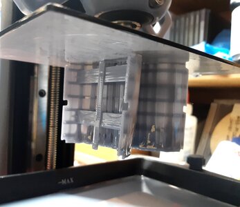
Finally got it ready to be printed. I rotated the two halves up on end, as shown before, and exported the STL file the Slicer uses. That's loaded into the "slicer" software that creates the file the printer uses that the whole model sliced into thin layers with information on how the printer should function; time to zap the first layer, then each layer after that, how fast and how far to move, etc.
second_cutter3d20231219.png

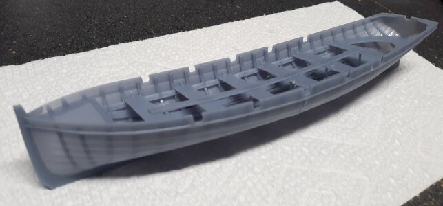
Then it's off to the races! Here it is about 45% through. I was concerned the planking might be too thin and I might have to adjust it and print it again.
con20231219a.jpg

But no, it's a keeper! I will thicken some things in the 3D model anyway, as I intend to share the STL on Thingiverse, and it will not scale down at all otherwise.
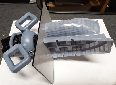
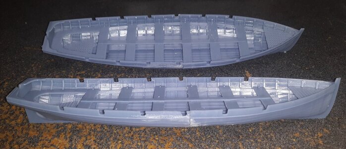
It chipped of in a couple of places trying to get the bow section off the build-plate, but that's easily fixed. The two halves meet up perfectly, though there's a little bit of "elephant's foot" where it was attached to the plate, a little filing of the seam once the two halves are bonded together will fix that.
con20231219b.jpg con20231219c.jpg

con20231219d.jpg

con20231219e.jpg con20231219f.jpg

sitting where it will live on the model
con20231219g.jpg
 
Last edited:
With the successful print of the 2nd cutter, I got into making the quarter-boats. The process is a little different, making this model more consistent. A lot of the 2nd cutter came over; seat, floorboards, knees, gratings, oar-locks, etc; most of which had to be adjusted to this boat which is slightly larger than the cutter.

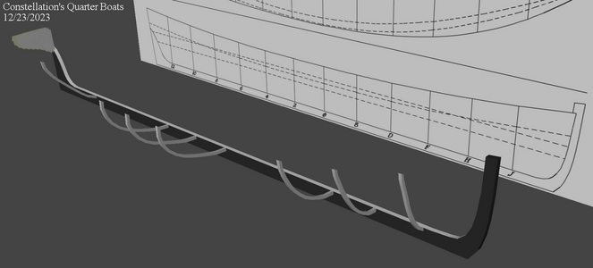
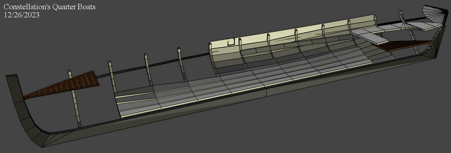
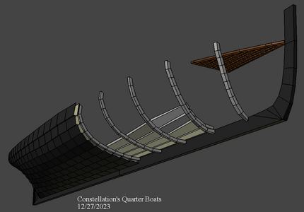
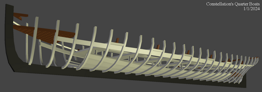
I used a wire-frame of a plank's cross-section to build up what amounts to frames. Each station gets 10 planks, but each station is a different "length." There no way in the software (Anim8or) to measure that length, so I measured the paper layouts I printed for making the boats in wood. I adjusted the "plank" to the length for that station and basically stamped it to get a clinker profile. These actually didn't go into the model, but were "traced" making two zig-zag wire-frames, one for the inner surface of the planks, the other for the outer surface. On the cutter I did this by eye, doing it this way would up saving a lot of time fairing the hull later.
This set up was also used to make the ribs which are done in 10 segments to match the planking.
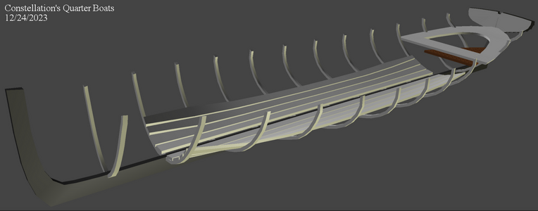
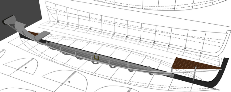
quarterboat20231223.png quarterboat20231223a.png quarterboat20231224a.png quarterboat20231225a.png

Each zig-zag wireframe in place in it's position on the model, adjusted to it's rib, "joined" with the others, and connected with what will be edges of the inner surface of the planks. The planking inner shell is the inside surface of the boat, the outer shell is the outside surface, and the gap between them gives the planking it's thickness.
quarterboat20231226b.png quarterboat20231227a.png
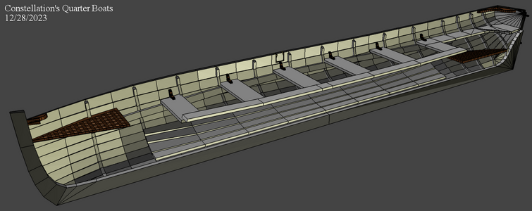
Once the the planking is faired as best as I can get it, I use a "slicing" function to basically create stations between the ones on the plan. These half stations will get ribs as well by copying a rib next door, and pushing and pulling it to be snug to the inner planking. These stations also get moved a little to make the boat a little less faceted. I may slice between these stations (1/4 stations) to smooth the hull even more, though these station won't need ribs.
I've just started installing the additional ribs back aft, and that's where I am so far.
quarterboat20231228a.png

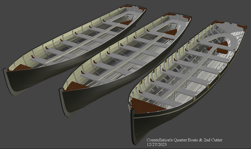
You may have noticed I only build the starboard side of the boat. Everything gets "mirrored" to the port side to make the other half. A nice aspect of symmetrical models :) Here's a a picture of the 2nd cutter with two unfinished quarter boats.
quarterboat_2ndcutter20231227.png
 
Last edited:
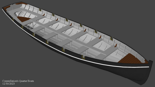
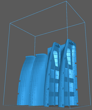
Worked on the quarter-boat model on New Years Eve hoping to start it printing before we went out, but I found too many little things to adjust, and gave up on that deadline. New Years Day, I finally declared her done, mirrored the port side, joined that parts, exported the STL, sliced it into a zillion layers, and started the 5-1/2 hour printing process.
quarterboat20240101a.png quarterboat20231230d.png quarterboat3d20240101a.png

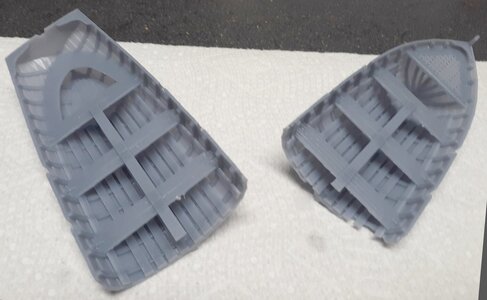
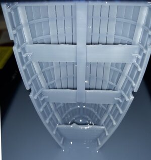
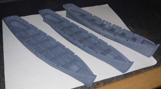
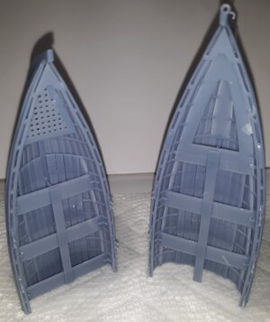
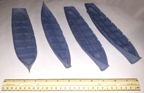
Finally they were printed
con20240102b.jpg con20240102c.jpg con20240102e.jpg

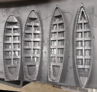
and all three boats together...
con20240102f.jpg

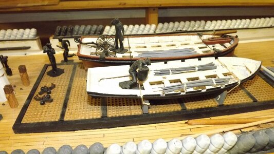
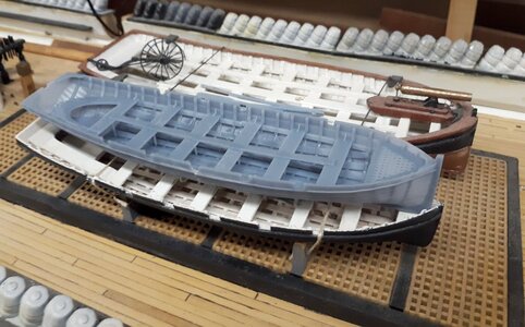
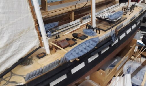
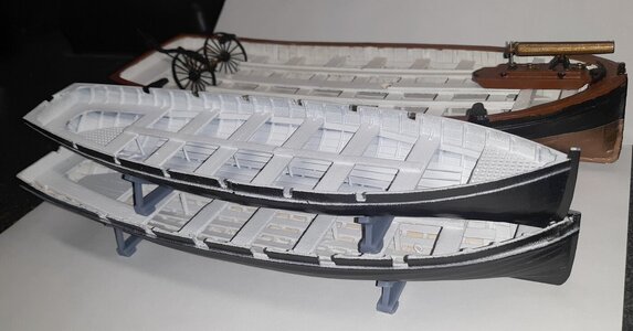
The three boats about where they will be on the main model...
con20240102i.jpg con20240102j.jpg

Meanwhile, the Stern boat progresses, here with the quarter boat for comparison.
starnboat20230102a.png
 
Last edited:
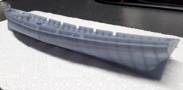
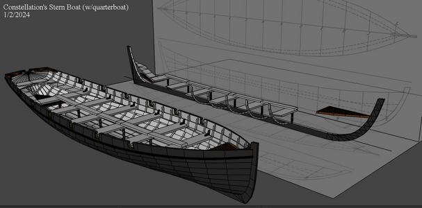
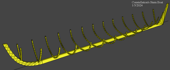
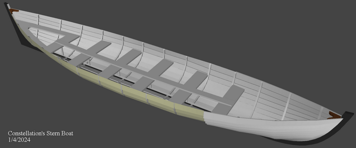
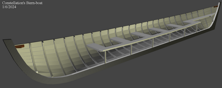
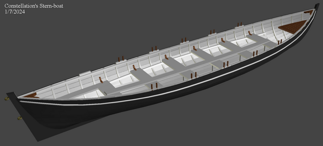
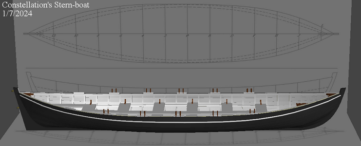
The last boat for Constellation is the whale-boat, called such because it's based on the boats carried by whalers. This boat will hang from davits on the ship's stern.
sternboat20230103a.png sternboat20230104a.png sternboat20230106a.png sternboat20230107b.png sternboat20230107c.png

The slicer says this one weights in at .83 ounces (23.6 grams), uses $.83 worth of resin, and take 5 hours and 25 minutes to print.
con20240108b.jpg con20240108c.jpg

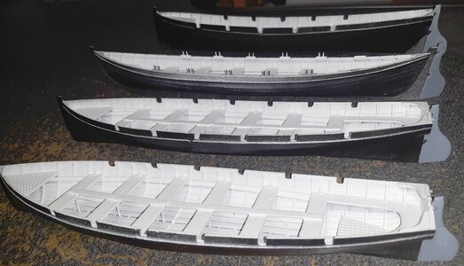
Here's all the boats together...
the 25'10" 2nd cutter, on the left, is 8.625" ( 219 mm) long,
the 28'2" whale boat, in the center, is 9.625" ( 245 mm) long,
the two 26' 6" quarter boats, on the right, are each 8.875" ( 226 mm) long.
con20240108g.jpg

Now to get some warmer weather so I can paint them and put in some hardware, like lifting rings.

Macedonian is gonna need boats too, but I have to research those a bit more before making them.
 
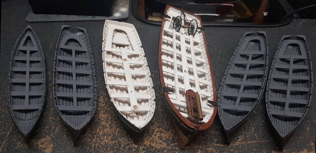
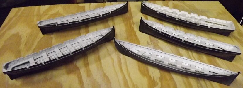
I gave the boats a coat of primer, and worked on the seams some more, but there's still more to do, especially on the quarterboats and whaleboat, which will be more visible. When it comes to doing Macedonian's boats, I'm going to make a jig to hold them so I'll have two hands to line things up and do a neater job bonding the two halves together. I hurried myself, and now I have to clean up after myself. I brought the 1st cutter and launch up to my desk to clean them of shop dust. All the boats need lifting rings installed, and the two hand-built ones need rudder gudgeons. They'll all get spars and sails, and bundles of oars lashed to the seats, and rudders laying in the stern-sheets. I think that's all the "detailing" I going to put into them.
con20240110a.jpg con20240113a.jpg

I had to get some white paint to do the interiors, and gave them a quick coat. The rub-rails reflect the light, they aren't painted, and aren't going to be. Just plain black out-board and white inboard; though i will paint the gratings a wood color.
con20240114a.jpg

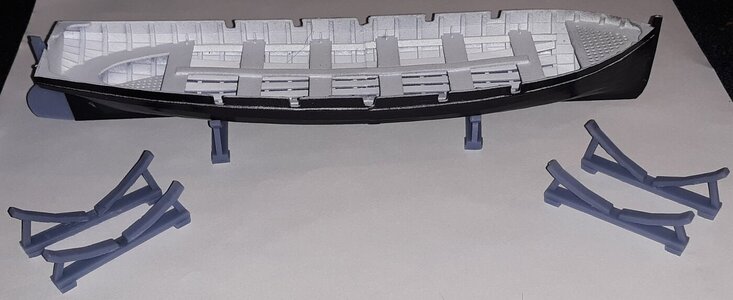
I made some simple boat chocks. If I figure out the Navy had a specific pattern for these things in 1855, I'll replace these, till then, these will have to do.
con20240115e.jpg con20240115c.jpg

and I made some rudders, though I still need to make one each for the 1st cutter and the launch. I made them to fir the gudgeon rings on the boats, but the rudders will get stowed inboard, and most likely, glued in place. I guess I need to make tillers too. :/
con20240115d.jpg
 
Back
Top