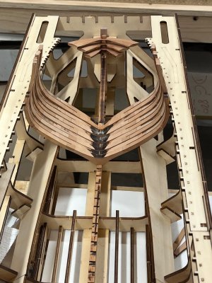
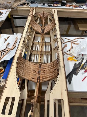
Corsair H.M.S. Enterprize Build Log

Ok, I have come to an issue with building frame #3.
I have the pieces for the bottom of the A side and the B side, and then there is a third one that I don't see on the frame plan and I don't see how it goes
 
No pictures today since all the frames pretty much look alike. :)
I have the second half of #3 glued up and the first half of both #4 and #5.

I think what I'm going to do is build all the frames and then verify they fit properly into the keel slot, and then sand all the bevels in them. This way I can test fit them all in the keel at once and don't have to keep taking the keel in and out of the construction jig. I can take it out once and verify all the bottoms fit then put the keel back in and leave it.
I have found some discrepancies in the instructions where they show no shift in a futtock, but one is thinner than the next so there has to be some sort of shift. Or maybe they made pieces out of the wrong thickness wood.
Hi Corsair, I think more of a thickness error.Frank
 
Hi Corsair, I think more of a thickness error.Frank
Perhaps. Unfortunately, I don't have spare material to make new ones from so I will have to work with what I have. On the positive side of this. I'm pretty sure that there isn't anyone that will look at my ship and say "Hey, that futtock is made wrong. Its too thin.". :) The only people that will know there is an issue is only those that read it here and I doubt even the best historian will pick out which ones are incorrect.
 
No pictures today since all the frames pretty much look alike. :)
I have the second half of #3 glued up and the first half of both #4 and #5.

I think what I'm going to do is build all the frames and then verify they fit properly into the keel slot, and then sand all the bevels in them. This way I can test fit them all in the keel at once and don't have to keep taking the keel in and out of the construction jig. I can take it out once and verify all the bottoms fit then put the keel back in and leave it.
I have found some discrepancies in the instructions where they show no shift in a futtock, but one is thinner than the next so there has to be some sort of shift. Or maybe they made pieces out of the wrong thickness wood.
I would reconsider this in one regard, especially if you plan to join both halves before they go to the keel.
An important first step is to insure your first futtocks fit their retrospective keel slots well. Whether keel is a bit thick in spots or futtock needs trimming, especially the ones made from 3 pieces.....they are often too tight to fit and need careful sanding......much easier done before assembly.
yes, you are correct and I was speaking "in general". To be more specific, I would build them but not attach the A and B halves yet to test fit them all into the keel.
Then I will glue the A and B halves together and bevel the edges.
Thank you for your recommendation. I'm glad there is so many people here ready to help. :D

If I glued the A and B halves together first, it would be really difficult to properly trim where the inside of the step would be at the bottom of the assembly.
l have sanded all A and B slots on the keel and also all the slots on the frames and test fit them before any assembly of the frame parts to avoid any problems that would prove difficult to put right at the frame/keel fitting stage. BTW did you ever resolve the question of the additional parts of the cross chock for the B side of frame 3. I ask because, l am working the other way to you (frame 7 to 1) and have found the same with frame 4. It is obvious which is the correct part for the cross chock but just wondering what the other ''spare'' part is for
 
l have sanded all A and B slots on the keel and also all the slots on the frames and test fit them before any assembly of the frame parts to avoid any problems that would prove difficult to put right at the frame/keel fitting stage. BTW did you ever resolve the question of the additional parts of the cross chock for the B side of frame 3. I ask because, l am working the other way to you (frame 7 to 1) and have found the same with frame 4. It is obvious which is the correct part for the cross chock but just wondering what the other ''spare'' part is for
No, I've not found out and Victor has not posted since I posted that question. I hope he is ok.
Yes, I have the same thing for #4 as well and there is possibly some others, but I won't know for a while. :) I'm still working up around frames 4 and 5. :) Yes, it's easy to tell which part is the center part for the frame for the normal construction. I'm just wondering what the additional part is for and want to make sure it doesn't go somewhere that I need to install it now. :) I'm affraid that I'll get the ship mostly assembled and will find out that it goes way down at the bottom by the keel. ROTF
 
My approach is also to test-fit the lower parts (floor timber in "A". and 1st futtocks + cross chock in"B") of each half-frame on the keel before making up and glueing the half frames together. Seems to work well...All my completed and bevelled frames (37-31) so far fit just right on the keel.

Alex R
Very glad to hear things are progressing well for you !
 
LOL Well, I guess it's my turn. I figured out today that somehow I managed to get the top half of one side of 3A frame way off the plan. So, I guess I guess I get to unglue it and makes adjustments. :) I also pretty much have frames 4 and 5 all glued up and test fit into the keel.
IMG_1598.jpeg
 
Last edited:
LOL Well, I guess it's my turn. I figured out today that somehow I managed to get the top half of one side of 3A frame way off the plan. So, I guess I guess I get to unglue it and makes adjustments. :) I also pretty much have frames 4 and 5 all glued up and test fit into the k
LOL Well, I guess it's my turn. I figured out today that somehow I managed to get the top half of one side of 3A frame way off the plan. So, I guess I guess I get to unglue it and makes adjustments. :) I also pretty much have frames 4 and 5 all glued up and test fit into the keel.
A little progress report. After 8-9 forward frames and my deadwood/transom debacle, moving now to some substantially bevelled rear ones, now only dry fit. Have about 1/2 “Y” frames and will now start to build, trim, fit, transom pieces.

View attachment 515787
Hi Corsair,the grooves for the paramezzal are not ? Frank
 
I added a picture above so you can see what I'm referring to. I just used my soldering iron to heat up the glue and take the frame apart at the offending joint. Cleaned up the joint and adjusted and re-glued. :)
I have not started putting frames into the jig yet as I am going to build all the frames first and then bevel the edges and then put them in the frame.
The problem was easy to spot when you put the 3A and 3B frames together. :)
Definitely a good reason to stick with PVA glue. :) Easier to de-bond. LOL
 
Tim
Those transom beams look great ! An inspiration: I may start the transom once I finish frame # 29, just to change procedures. Maybe build transom beams, wing transom and fashion piece and then continue with the can't frames. Today I also made an error building frame # 30 -messed up the spacings-I had to unglue the large top-timbers an re-space them. This tell me it is time for a break.

Alex R
Those are the old ones, now replaced. Among other things the back bevels were less than great.

New ones installed. Inside bevel sanding still rough, outside done and look pretty nice, glad I re did them……try and get a photo up..

Tim
P.S. A possible tip for the class you might find helpful.
When I re did the transoms I did not want to do the final angle sanding to butt against the 1/2 frame when they were glued up, incase I screwed up, they’d be a bear to remove. I did not want to do it unglued cause they really need to be finished togeather…angle for all four, the same.
What workd out quite well is I secured the notches onto a piece of square stock and spaced them all with double sided foam tape, about the same spacing which allowed final sanding as one non moving unit, saved a ton of time and came out nicely.
IMHO, this is the single trickiest area….glad I’m done with the angles.

IMG_0677.jpeg
 
Last edited:
Tim
Those transom beams look great ! An inspiration: I may start the transom once I finish frame # 29, just to change procedures. Maybe build transom beams, wing transom and fashion piece and then continue with the can't frames. Today I also made an error building frame # 30 -messed up the spacings-I had to unglue the large top-timbers an re-space them. This tell me it is time for a break.

Alex R
been there. :)
 
Ok, the frame half of #3 is fixed, I've trial fit the frame halves of 3, 4 and 5 into the keel and I have trimmed down the chocks on 3 and 4. Maybe rather than completing the construction of all the frame halves and then gluing them. I'll start gluing the frame halves together as I progress. :) That will give me a little variety.
 
Back
Top