Cross Section - HMS Leopard 4th Rate 1790 - 1:44

Hey Doc,
Your Leopard is looking really sharp. I too built an anchor from wood and if compared to a brass one aperson would be hard pressed to tell the difference. I did see a build here on SOS that I draw my inspiration from and you may be pleased to know that it has a lot of details in the hold.
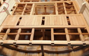
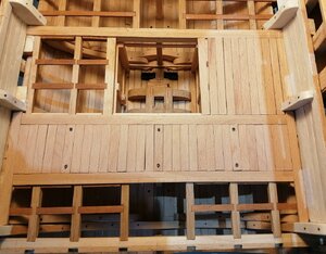
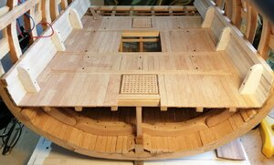
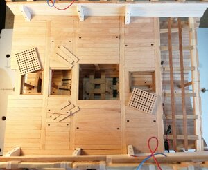

Hopefully this link may assist you in determining what you may want to add and/or omit from your build.

Raymond
 
Thanks for the comments, Kurt and Raymond and to the others for likes and stopping by.

Raymond, that build of Karl (Jeronimo) is one of the many that I've been snooping around. It was on Karl's build log where I saw the idea of lashing an anchor to one of the pillars.


Noticed that in my previous post I hadn't posted the pics of the gratings for the orlop deck. These are a little easier than the gun deck gratings as they are flat with no round-up or camber.

Gratings 2.jpg

Gratings 2..jpg

This is where I intend to position the anchor. (It's just 'posing' there for the photo, it's not secured.)


IMG_20200619_172752.jpg
 
Thanks for that helpful link, Raymond.

Some progress with the orlop deck planking.

As I seem to keep saying - - there isn’t a lot of details for many aspects of this build I’m attempting and with my previous P.O.B. build, there was no need to do any planking in the orlop. At that time I could see that the orlop planking appeared different to the planking of the gun decks from the only stylised drawing I have of the orlop deck.

Here is that drawing >

L  1 - Orlop.jpg


It has only been recently that I have understood why the orlop planking is different when I have been looking at some other build logs. These planks are removeable in order to create extra access to the hold. As they’re laid in athwartships sections I was able to tackle one section at a time instead of working from the centreline ‘out’ towards the hull sides.

Here’s the first section I attempted >

First planks.jpg


The 3 empty spaces in the photo above are for these >
Planks lift rings.jpg

The recesses for the rings were cut on the milling machine.

I couldn’t imagine that every plank would need lifting rings, and these 3 planks would serve as “starters” to enable the lifting of other planks as required

A week or so later and about 80% had been done >

Floors.-  4 - 5.jpg
Floors.4 - 5.jpg

With the gratings and a few planks lifted out >

Floors.- 4 - 5.jpg


The space immediately ahead of the fore grating is going to accommodate this >

Floor 100A.jpg
Orlop planking complete >
Floor-100.jpg

Floor 100..jpg

It’s evident from some of the above photos that the orlop inner hull planking has been done . . . and it is painted white. I understand that on all these sailing ships the practice was to paint all the “walls” and “ceilings” on all decks from the orlop upwards, so, I’ll be painting all of these parts white. As it did on these real ships, the white paint will help create a brighter interior in this section as well.
 

Attachments

  • L  1 - Orlop.jpg
    L 1 - Orlop.jpg
    341.4 KB · Views: 1
  • First planks.jpg
    First planks.jpg
    264.8 KB · Views: 1
  • Planks lift rings.jpg
    Planks lift rings.jpg
    323.7 KB · Views: 1
  • First planks-.jpg
    First planks-.jpg
    345.9 KB · Views: 1
  • Floors.-  4 - 5.jpg
    Floors.- 4 - 5.jpg
    405.2 KB · Views: 1
  • Floors 4 - 5.jpg
    Floors 4 - 5.jpg
    230.1 KB · Views: 2
  • Floors.- 4 - 5.jpg
    Floors.- 4 - 5.jpg
    267.1 KB · Views: 3
Thanks for that helpful link, Raymond.

Some progress with the orlop deck planking.

As I seem to keep saying - - there isn’t a lot of details for many aspects of this build I’m attempting and with my previous P.O.B. build, there was no need to do any planking in the orlop. At that time I could see that the orlop planking appeared different to the planking of the gun decks from the only stylised drawing I have of the orlop deck.

Here is that drawing >

View attachment 161066


It has only been recently that I have understood why the orlop planking is different when I have been looking at some other build logs. These planks are removeable in order to create extra access to the hold. As they’re laid in athwartships sections I was able to tackle one section at a time instead of working from the centreline ‘out’ towards the hull sides.

Here’s the first section I attempted >

View attachment 161067


The 3 empty spaces in the photo above are for these >
View attachment 161068

The recesses for the rings were cut on the milling machine.

I couldn’t imagine that every plank would need lifting rings, and these 3 planks would serve as “starters” to enable the lifting of other planks as required

A week or so later and about 80% had been done >

View attachment 161069
View attachment 161070

With the gratings and a few planks lifted out >

View attachment 161071


The space immediately ahead of the fore grating is going to accommodate this >

View attachment 161072
Orlop planking complete >
View attachment 161073

View attachment 161074


It’s evident from some of the above photos that the orlop inner hull planking has been done . . . and it is painted white. I understand that on all these sailing ships the practice was to paint all the “walls” and “ceilings” on all decks from the orlop upwards, so, I’ll be painting all of these parts white. As it did on these real ships, the white paint will help create a brighter interior in this section as well.
Very good execution and view for the detail
Here a photo of the original Victory - Orlop deck with planking over the hold
Orlop Vic.JPG
 
Thanks for that comment, Uwe.

It must be 36 years since I last visited Victory, my boys were just young then.
We were booked for a stay in Portsmouth with a visit to Victory top of the list earlier this month but Covid 19 scuppered that trip.
We'll just have to wait until 'the coast is clear' again and re-book another visit.

For anyone either in, or visiting the U.K. there is another ship well worth a visit in the North East of England. H.M.S. Trincomalee, a Leda class 38 gun frigate built in 1817 in India for the Royal Navy is still afloat in her berth in Hartlepool.
It's set in a purpose built 18th/early 19th century dock area and this is the first view as you enter the car park.
IMG_6656.JPG
HMS Trincomalee (2).jpg
 
After I made the first batch of barrels other small projects around the ship have kept me busy. In the last couple of weeks I've expanded my stock of barrels to 30. They may be small but they sure take a bit of time to get them to where I want them!
Snooping around other build logs has given me some ideas of what to include in the hold.
In a previous post above (#44) I showed the orlop deck with its planking complete. It would have been a little easier, and more sensible, if I had completed the hold first as it proved a little awkward getting some stuff tucked away under the orlop beams and planks.

I made a couple of racks for holding barrels ~ and anything else that could be stowed there. Here's the one for the port side.
Rack...jpg

The cut-out parts are to accommodate the riders. I couldn't imagine that barrels would just be placed on there without being secured in some way, so I added a few cleats and lashed the barrels down.
Rack prt.-.jpg

And in position >
Rack prt.jpg

For ballast I bought some aquarium gravel at a grade that I thought was about right for scale >
Ballast.jpg
and the first 'batch' of gravel in the ship >
Hold.. (2).jpg

~ but when I saw it with these barrels sitting in it, it just didn't look like the right scale. I had some left-over ballast gravel from a model railway project and it seemed to be more in scale, so railway ballast it is >
Hold F (3).jpg

Both sides of the fore end of the section now ballasted >
Hold F.jpg

When I've finally got all the barrels squeezed in under the orlop this anchor will be lashed to the pillar >
Hold A.jpg

Hold A..jpg

That orlop deck has proved very useful as a timber storage area!
 
Hello Jim,
She looks great. The extra details you've added makes it seem as she is already sea worthy. I'm currently still working on my barrels but jumping an the ledges of the orlop deck, which by the way, have not yet been glued in place. I still have to make the chain pumps and elm trees before I seal off access to the hold. The great thing about having a check list is that you ensure everything gets done before going on to the next step.

Raymond
 
Thanks for the comments, Raymond, and to the others for the likes and visits.

Hello Jim,
I was just re-glancing over your posts and I just realized that you also cut the notches for the limber gates. Kudos to you Sir.

Raymond
----------------------------------------------------------------------------------------------------------------------------------------

Raymond ~ it's by snooping around other build logs that I learn about 'minor details' like limber holes/notches!
 
A short update after what feels like a long time preparing all these little things.

I didn't want to put too many barrels in the fore part of the section so that the view to the inside wouldn't be obscured. I now have as many barrels in there as I want, some more ballast added, the anchor is now lashed to the pillar and a few lengths of rope have been added.
Hold fore..jpg
Hold fore.jpg

At this point only some ballast had been added to the aft part of the section.
I made an open topped crate for holding some blocks and dead eyes. These had been left over from the previous build and were my 'rejects' as they were quite awful as the holes were in places where they shouldn't have been! Some time was spent on them trying to get them to look more 'proper' even though they won't really be seen when tucked away under the orlop deck.
Crate..jpg

Right now, all I have in that aft part is that crate and some lengths of rope of various gauges, some lying on the deck and some hanging on the pillars.
Hold aft.jpg
20200729_202754 (2).jpg

For the moment, I'm putting the hold "on hold" as I'll be looking at doing another project for the build. That aft part is quite roomy so I can re-visit it later and get more stuff in there.
 

Attachments

  • Crate.jpg
    Crate.jpg
    200.1 KB · Views: 0
A short update after what feels like a long time preparing all these little things.

I didn't want to put too many barrels in the fore part of the section so that the view to the inside wouldn't be obscured. I now have as many barrels in there as I want, some more ballast added, the anchor is now lashed to the pillar and a few lengths of rope have been added.
View attachment 169226
View attachment 169227

At this point only some ballast had been added to the aft part of the section.
I made an open topped crate for holding some blocks and dead eyes. These had been left over from the previous build and were my 'rejects' as they were quite awful as the holes were in places where they shouldn't have been! Some time was spent on them trying to get them to look more 'proper' even though they won't really be seen when tucked away under the orlop deck.
View attachment 169228

Right now, all I have in that aft part is that crate and some lengths of rope of various gauges, some lying on the deck and some hanging on the pillars.
View attachment 169230
View attachment 169231

For the moment, I'm putting the hold "on hold" as I'll be looking at doing another project for the build. That aft part is quite roomy so I can re-visit it later and get more stuff in there.
Hi Doc
it looks beautiful, I learned allot
 
Thanks, shota70 and Eric for your comments, and the other for the likes and visits.

Diverted away from the internal of the ship to the outside. As the wales are hook and butt planks I was a bit keen to see how I would get on with creating them. In my other build the wales were also hook and butt, but at about half of the scale of this one I found them quite difficult and eventually opted to make the easier top and butt planks.
They looked like this >
Wales T & B.jpg
and the wales looked like this >
Wales T & B..jpg

What I wanted was for the wales to look like these >

Wales H & B.jpg

I see lots of builders use metal templates to form the wales. I did consider this route but in the absence of much suitable metal, the prospect of having to create two different profiles and with the possibility of getting the templates wrong, I opted to cut each individual plank at the bandsaw.
I reckoned I would need 24 planks so I set about to make 28 - "just in case".
Here are 16 of the blanks before presenting them to the bandsaw. >
Wale blanks 16.jpg

24 of them after 'the cut' >
Wales 24.jpg

and arranged more neatly >
Wales 24..jpg

I opted to paint the planks before fitting to the hull. The first three "starter" planks >
Wales 3..jpg

Port side >
Wales - Port.jpg
Wales - Port..jpg

Starboard side >

Wales Sbd.jpg


Now ~ for something a little less challenging . . .
 
Jim, that looks great. I am still working on the Admiral's Honey-Do list but the moment I finish I'll complete the orlop deck beams in order to get started on the exterior hull.

Raymond
 
Last edited:
Thanks for your comment, Raymond. "Honey Do lists" are just a fact of married life!

Leaving any further hull planking off for a later date. Moved back 'inside' as I want to get the fittings on the orlop deck started. But before I can do that I have to make the lower gun deck beams as they'll be necessary in order to establish the height of the upper well, the carpenter's walk and other structures.
I decided that I would laminate the beams for this and the upper gun deck as I believe that will produce beams of a constant curvature. When doing deck beams for my other build I found it a bit tricky getting them all to have the same curve.
To do this I made a former from a simple piece of softwood. To get the curve I wanted I just used the simple 'hacksaw blade and 3 nails system'. I first established the rise I wanted, knocked in 3 nails, one at each end and one in the middle, bent the hacksaw blade into position and drew the curve. The following photo may make it clearer >

Beam curve.jpg

Cut the curve at the bandsaw and lightly sanded both curves.
Beam former.jpg

From my previous experiences of laminating strips of wood into a curve, I knew that the wood naturally 'springs back' a little from the curve set by the former so when drawing the curve I set it a little 'steeper' than the finished curve that I wanted. Here's the first laminated beam. (This sides of this hadn't been sanded and the laminated appearance diminishes after sanding, but in any case the sides and underside of these beams will be painted with the 'white stuff' before fitting.) >
Beam L.jpg

Of course, what I mentioned above ("the wood springs back a little") just didn't happen in the case of these beams! --- and I had 6 beams that were just a little too high in their rise at the centre and just didn't look right. After being clamped on a flat surface for about 4 hours the 'wild' curve in these 6 beams was 'tamed' down to a more acceptable height.
L G Beams.jpg

This was the moment when I realised an awful truth about my build. I DO belong to the "measure twice, cut once" club and I always try to make doubly sure of measurements and dimensions before committing any knife or saw to a workpiece -- or in this case, committing something to the glue. I'm mystified as to how this error arose -- but there it was in front of me. Somehow I had glued the port side lower gun deck clamp about 1.5mm higher than the starboard clamp at the fore end of the section. That dimension diminished a little to about 1mm at the aft end.
That clamp was "welded" on with epoxy resin and to have tried to have removed it would have caused some devastation inside the hull -- so that wasn't going to happen.
Instead, in order to level up each side of the beams, I notched a little out of the underside of them on their port side ends. Job done.

Now I'm off to repeat "measure twice, cut once; measure tw--- --- "
 
Thanks for the likes and visits.

Now that the beams were established in their positions (although not yet secured) the measurements of everything else to be placed on the orlop deck could also be established.
I decided to start with the upper well and the first little challenge I faced was to decide what format it would take. I say that as there is a bit of a conflict between the only two drawings I have of that structure.
In the schematic drawing it looks like this >

Upper Well boards.jpg

In the above drawing the upper well (#17) appears with a door on the front as well as a door on the rear, also the planking appears to be 'conventionally' flat.
Here's the other image I have >

0005-Section.jpg

In that image, which is viewed looking towards the stern, there is no door on the front of the upper well (#9) and it's not clear from that whether the boards are flat or louvred.
On several other builds of ships from a similar period I see the builders have made louvred walls, so following these as a fairly reliable guide I opted to take that route.
Out came the milling machine again. On a previously used jig I screwed on a simple triangle against which the posts could be secured and slotted >

Upper Well...jpg
Upper Well.jpg
The opposite angled slots would be cut on the other side (right-hand side) of the triangle. I soon realised that if both 45 degree angles weren't exactly equal there would be a visible discrepancy in the finished slots. In the following image, angle "A" would have to be exactly the same as angle "B"
Louvre Jig.jpg
So, to ensure that the 'left-hand' slots were a mirror image of the 'right-hand' slots I did all the left-hand cuts first then unscrewed and flipped the triangle round before cutting the right-hand cuts. (After I had cut the first post I added these extra screw clamps as I found these sliding clamps weren't quite up to the task.)
Louvre Jig..jpg
I used over-length posts to mill the slots as this made it easier to get them all matching cut lengths. The first un-cut post >

Upper Well-.jpg

I inserted a piece of 1mm brass wire in the centre of each post/pillar to facilitate correct positioning on the deck. >
U W Pins.jpg

All 5 posts in position >
Upper Well Pillars.jpg

In line with what I saw on other builds, I opted to place one door on the starboard side.
It seemed to me that it would have been quite tricky to have tried to glue in all the slats with the posts in their positions on the deck, so time for another little jig.
The following pic shows the 5 holes for the brass pins >
U W Position.jpg

I held a piece of paper over the deck while piercing holes to correspond with the 5 drilled holes in the deck.
I cut the paper down to size and glued it on to a piece of 6mm plywood, drilled 5 holes in the plywood at the indicated points and attached that to a strip of wood so that it could be held in the vice. >
U W Position..jpg

First 'short wall' done >

U W JIg.jpg
I found the best way was to insert the bottom slat first, then the top one. Doing that helped ensure that the posts would remain parallel to each other while fitting the other slats. >
U W Jig...jpg
U W Jig..jpg
Then, quicker than I was expecting, it was complete. It wasn't nearly as challenging as I thought it would be.
U.W. on jig.jpg

Then on board >
U.W.-.jpg
U.W.--.jpg
U.W. beams..jpg
U.W. beams.jpg
 
Kent wrote:
"Superb workmanship. You must have been a surgeon.
Kent"

Kent,
I'm not a surgeon, and despite my username, I've never been "just" a doctor either!
("The Doc" is just a nod to Valentino Rossi ~ anyone into Moto GP [Motorcycle racing] will know who Valentino is.)
 
Back
Top