- Joined
- Dec 15, 2019
- Messages
- 99
- Points
- 143

Hi Kurt,
Just a few weeks back my knowledge of the pumps was very limited as well.
Only from my research have I found a fair amount and what seems quite a dull subject has proved to be quite fascinating.
As far as I understand from what I've found out, there appears to have been three different systems (possibly more?) for the elm tree pumps alone.
I've tried to illustrate the three types below.
First, what appears to be the most simple system -- a direct supply >
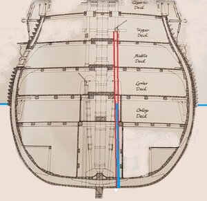
In the above drawing the water level is shown in blue; the pump tube in red. In this system the tube exited directly through the bottom of the hull and just drew sea water directly from there.
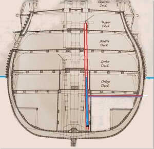
The next drawing shows what just appears to be a bit of a variation of the above. The intake pipe is situated in the hull side around 3 feet (900mm) below the waterline. I believe (although I may be wrong?) that the bottom end of the vertical tube was open above the bilges with a control valve for the purpose of occasionally flushing some clean sea water into the bilges as the bilge water would become foul and stinky. That water would then be pumped out using the chain pumps. >
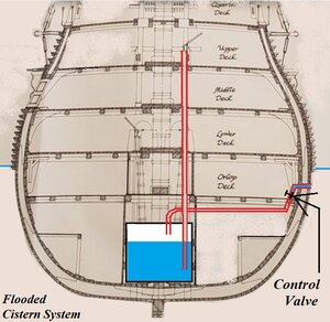
The following drawing is an approximate representation of the 'flooded cistern' system where a watertight cistern in the hold could be filled (to a desired level) by means of the pipe that exited the hullside. I understand that pipe would have a valve to control the amount of water allowed into the cistern. When the brake pump was activated it would draw water directly from that cistern.
I should say that I can't guarantee that the above info is 100% accurate but it is my understanding of what I have read in the last few weeks.
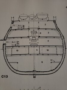
Note from these drawings above that there is a brake pump on the lower deck as well as one on two decks above, on the upper deck while the chain pumps are both on the lower deck.
While I was researching the pumps I discovered that the worst disaster to befall an English warship in home waters (and not in battle) was the result of a procedure adopted in order to carry out what should have been simple maintenance/repair to the starboard inlet pipe for the cistern on one of the biggest 1st rate ships of the 18th century.
This is an interesting read and can be found here > https://dawlishchronicles.com/the-loss-of-hms-royal-george-1782/
Just a few weeks back my knowledge of the pumps was very limited as well.
Only from my research have I found a fair amount and what seems quite a dull subject has proved to be quite fascinating.
As far as I understand from what I've found out, there appears to have been three different systems (possibly more?) for the elm tree pumps alone.
I've tried to illustrate the three types below.
First, what appears to be the most simple system -- a direct supply >

In the above drawing the water level is shown in blue; the pump tube in red. In this system the tube exited directly through the bottom of the hull and just drew sea water directly from there.
The next drawing shows what just appears to be a bit of a variation of the above. The intake pipe is situated in the hull side around 3 feet (900mm) below the waterline. I believe (although I may be wrong?) that the bottom end of the vertical tube was open above the bilges with a control valve for the purpose of occasionally flushing some clean sea water into the bilges as the bilge water would become foul and stinky. That water would then be pumped out using the chain pumps. >

The following drawing is an approximate representation of the 'flooded cistern' system where a watertight cistern in the hold could be filled (to a desired level) by means of the pipe that exited the hullside. I understand that pipe would have a valve to control the amount of water allowed into the cistern. When the brake pump was activated it would draw water directly from that cistern.

I should say that I can't guarantee that the above info is 100% accurate but it is my understanding of what I have read in the last few weeks.
Note from these drawings above that there is a brake pump on the lower deck as well as one on two decks above, on the upper deck while the chain pumps are both on the lower deck.
While I was researching the pumps I discovered that the worst disaster to befall an English warship in home waters (and not in battle) was the result of a procedure adopted in order to carry out what should have been simple maintenance/repair to the starboard inlet pipe for the cistern on one of the biggest 1st rate ships of the 18th century.
This is an interesting read and can be found here > https://dawlishchronicles.com/the-loss-of-hms-royal-george-1782/
Last edited:


