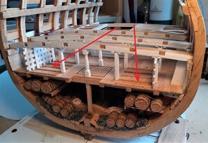
-

Win a Free Custom Engraved Brass Coin!!!
As a way to introduce our brass coins to the community, we will raffle off a free coin during the month of August. Follow link ABOVE for instructions for entering.
-

PRE-ORDER SHIPS IN SCALE TODAY!
The beloved Ships in Scale Magazine is back and charting a new course for 2026!
Discover new skills, new techniques, and new inspirations in every issue.
NOTE THAT OUR FIRST ISSUE WILL BE JAN/FEB 2026
You are using an out of date browser. It may not display this or other websites correctly.
You should upgrade or use an alternative browser.
You should upgrade or use an alternative browser.
Cross Section - HMS Leopard 4th Rate 1790 - 1:44
- Thread starter The Doc
- Start date
- Watchers 17
-
- Tags
- cross section leopard
- Joined
- Dec 15, 2019
- Messages
- 99
- Points
- 143

Kent,
While I DO use knives, mini-saws and a mini chisel to make some cuts, I have a very good friend who takes care of the intricate cuts for things like gratings, half laps and other things like the louvre slots that I've just done . . . and that friend is my Proxxon mill. My other main machine is my bandsaw on which I mill my timber down to the various thicknesses and widths that I need.
I've done so much already on that Proxxon mill and still have a lot to do and I just don't know how I would do all that without the mill.
- Joined
- Dec 15, 2019
- Messages
- 99
- Points
- 143

Time for something different - - time for a walk . . . a carpenter's walk.
Of all the build logs I've looked at, I can't remember seeing any which have included the carpenter's walk, so I wanted to have a go at including at least part of one.
Building a section as big as this has advantages and disadvantages. One of the disadvantages is that, although much more 'stuff' can be included, some of that 'stuff' could be obscured from view by other items.
For that reason, one item I have decided to omit is the mid-ships sail room. In the same area where that sail room would be is the aft end of the carpenter's walk and cable tier and to include these would just be an added feature rather than creating a 'blind spot.'
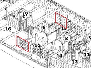
From this drawing I can see that I will be able to include one and a half sections of the lattice-work partitions that make up the carpenter's walk. I've outlined the two sections in red. >
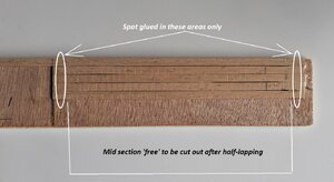
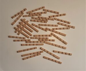
Just these two small parts involve 96 half-laps, so time to recruit the mill again. I used strips of beech in the dimensions of 4mm X 2mm and used a 2mm cutter to mill the 4mm wide half laps. In order to cut the half laps I spot glued two batches of strips to pieces of 6mm plywood. The strips were glued as shown in the following >
That allowed me to make the cuts in groups of 4 as there are 4 half lap joints vertically and horizontally in each section. The 2mm cutter also took care of the vertical grooves in the posts.
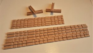
Then cut closer to their final lengths.
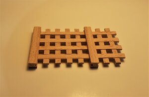
Trimmed and assembled.
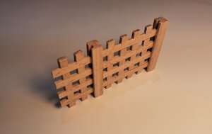
With the white stuff.
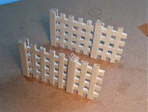
First 'test ride' before the white stuff.
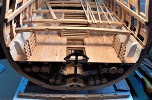
With a few of the cable tier pillars and ventilation beams.
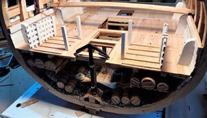
The upper well and the blanks of the lower gun deck beams sitting in position (dry fitted) >
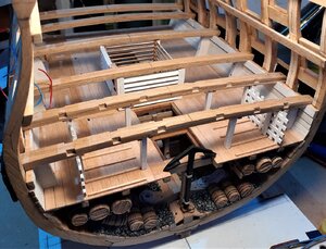
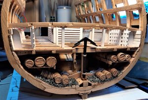
Of all the build logs I've looked at, I can't remember seeing any which have included the carpenter's walk, so I wanted to have a go at including at least part of one.
Building a section as big as this has advantages and disadvantages. One of the disadvantages is that, although much more 'stuff' can be included, some of that 'stuff' could be obscured from view by other items.
For that reason, one item I have decided to omit is the mid-ships sail room. In the same area where that sail room would be is the aft end of the carpenter's walk and cable tier and to include these would just be an added feature rather than creating a 'blind spot.'
From this drawing I can see that I will be able to include one and a half sections of the lattice-work partitions that make up the carpenter's walk. I've outlined the two sections in red. >

Just these two small parts involve 96 half-laps, so time to recruit the mill again. I used strips of beech in the dimensions of 4mm X 2mm and used a 2mm cutter to mill the 4mm wide half laps. In order to cut the half laps I spot glued two batches of strips to pieces of 6mm plywood. The strips were glued as shown in the following >

That allowed me to make the cuts in groups of 4 as there are 4 half lap joints vertically and horizontally in each section. The 2mm cutter also took care of the vertical grooves in the posts.

Then cut closer to their final lengths.

Trimmed and assembled.


With the white stuff.

First 'test ride' before the white stuff.

With a few of the cable tier pillars and ventilation beams.

The upper well and the blanks of the lower gun deck beams sitting in position (dry fitted) >


- Joined
- Dec 15, 2019
- Messages
- 99
- Points
- 143

Thanks for the likes and the visits here.
Since I had finished the upper well structure and everything in that central part of the orlop deck seemed OK I was keen to have a try at the more complicated mid-ships beam which has the beam arms attached.
My only previous experience with deck beams, carlings and ledges was with the slightly simpler, flat and square orlop ones.
The curved beam arms looked more complicated, although the basic cutting of them was reasonably straightforward with the bandsaw and smoothing them with a sanding drum in the drill press . . . but first I had to decide on their configuration.
I had a good rummage through the Fifty Gun Ship book (there are no plans for the deck beams in the plans/drawings I have) and could only find a few drawings of beams for 50 gun ships from an earlier period.
Here is the best one I could find with the mid-ships beam with beam arms circled in red >
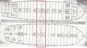
Having looked at so many build logs of Royal Navy ships from the late 1700s, what I saw in that drawing above differed somewhat as far as that central beam was concerned, so I opted to go with what I was seeing in the other builds.
This is first attempt at the rather complicated joint between the beam and the arm >
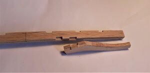
. . . and 'clicked' together >
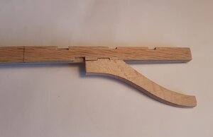
First dry fit >
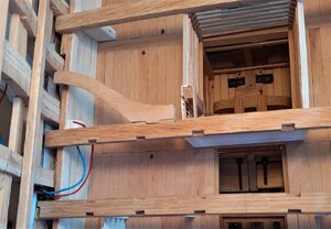
Both beam arms with one carling on each >
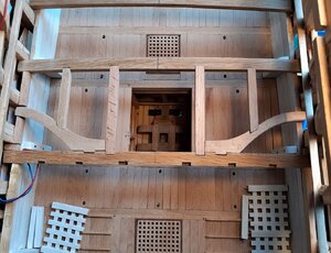
On the models I've viewed there have been some with two ledges between beams, some with three ledges and some with four ledges, so, at first I opted to go with two ledges >
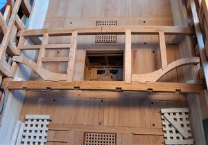
I was quite happy with that first attempt, but the more I looked at it the more I began to think there probably should be at least three ledges between the two beams.
So ~ ~ ~ for the other side I decided to go for three.
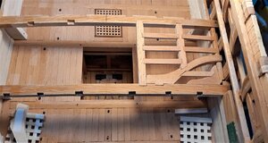
Doing three ledges involved creating more mortices -- reasonably easy to do the 'square' mortices, but a bit more of a challenge to do the angled mortices in the beam arm and in the lodging knee.
Here, a bit of an incongruous picture showing the difference between the two sides >
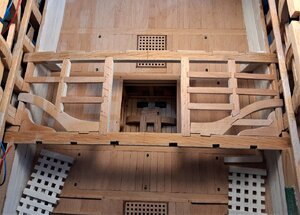
OK ~ it may look a little odd but as the deck will be planked and nothing of the beams, carlings and ledges will be seen, I am leaving it the way it is. There was quite a lot of work and time spent on these beam arms and associated 'bits' - even just the simpler starboard side, and in reality it was something of an experiment as I wanted to see if I could tackle that new challenge.
Here, the beams, the arms, carlings and ledges are now glued in position with the upper well also in position.
In this picture only the starboard lodging knee was still to be fitted (it can be seen lying on the cable tier) >
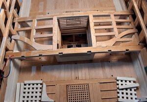
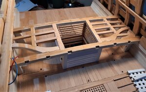
Since I had finished the upper well structure and everything in that central part of the orlop deck seemed OK I was keen to have a try at the more complicated mid-ships beam which has the beam arms attached.
My only previous experience with deck beams, carlings and ledges was with the slightly simpler, flat and square orlop ones.
The curved beam arms looked more complicated, although the basic cutting of them was reasonably straightforward with the bandsaw and smoothing them with a sanding drum in the drill press . . . but first I had to decide on their configuration.
I had a good rummage through the Fifty Gun Ship book (there are no plans for the deck beams in the plans/drawings I have) and could only find a few drawings of beams for 50 gun ships from an earlier period.
Here is the best one I could find with the mid-ships beam with beam arms circled in red >

Having looked at so many build logs of Royal Navy ships from the late 1700s, what I saw in that drawing above differed somewhat as far as that central beam was concerned, so I opted to go with what I was seeing in the other builds.
This is first attempt at the rather complicated joint between the beam and the arm >

. . . and 'clicked' together >

First dry fit >

Both beam arms with one carling on each >

On the models I've viewed there have been some with two ledges between beams, some with three ledges and some with four ledges, so, at first I opted to go with two ledges >

I was quite happy with that first attempt, but the more I looked at it the more I began to think there probably should be at least three ledges between the two beams.
So ~ ~ ~ for the other side I decided to go for three.

Doing three ledges involved creating more mortices -- reasonably easy to do the 'square' mortices, but a bit more of a challenge to do the angled mortices in the beam arm and in the lodging knee.
Here, a bit of an incongruous picture showing the difference between the two sides >

OK ~ it may look a little odd but as the deck will be planked and nothing of the beams, carlings and ledges will be seen, I am leaving it the way it is. There was quite a lot of work and time spent on these beam arms and associated 'bits' - even just the simpler starboard side, and in reality it was something of an experiment as I wanted to see if I could tackle that new challenge.
Here, the beams, the arms, carlings and ledges are now glued in position with the upper well also in position.
In this picture only the starboard lodging knee was still to be fitted (it can be seen lying on the cable tier) >


Last edited:
- Joined
- Dec 15, 2019
- Messages
- 99
- Points
- 143

Re-visited the aft end of the hold and fitted a couple of racks, each of which has a coil of rope on it - more to follow when I get some more suitable rope.
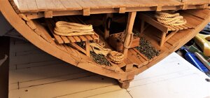
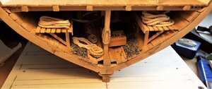
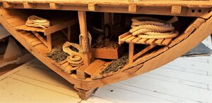
Then returned to the fore end of the orlop deck to get the two deck beams secured since the carpenter's walk and cable tier were now done. Although quite small, turning the deck pillars proved quite tricky. I was using 6mm square stock and as I don't have a 4 jaw lathe chuck I could only use the point of the drive attachment in my drill and the point of the idler at the other end so it was a bit of a slow process.
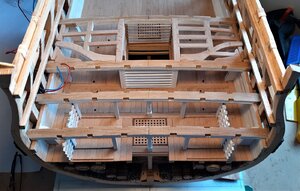
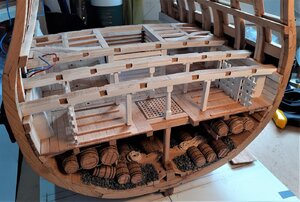
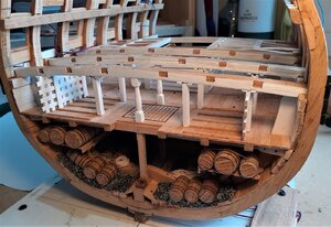
(It was only the central beam pillars that get turned, the cable tier pillars are just square in section.)
Still have to do the carlings, ledges and knees for these two beams but I've made a start on the structures of a few of the rooms at the aft end of the orlop deck to allow me to get the other two deck beams fixed in place.


Then returned to the fore end of the orlop deck to get the two deck beams secured since the carpenter's walk and cable tier were now done. Although quite small, turning the deck pillars proved quite tricky. I was using 6mm square stock and as I don't have a 4 jaw lathe chuck I could only use the point of the drive attachment in my drill and the point of the idler at the other end so it was a bit of a slow process.


(It was only the central beam pillars that get turned, the cable tier pillars are just square in section.)
Still have to do the carlings, ledges and knees for these two beams but I've made a start on the structures of a few of the rooms at the aft end of the orlop deck to allow me to get the other two deck beams fixed in place.
Last edited:
- Joined
- Dec 15, 2019
- Messages
- 99
- Points
- 143

Hi Uwe,
These wooden battens attached athwartships-wise across the floor of the orlop deck were part of the cable tier. When the anchor cable was heaved into the ship when weighing anchor it was saturated with water. The cables were fed down onto the orlop deck for storage until needed next and these wooden battens partially held the cable(s) off the deck to help with ventilation and the drying of the cables.
** Edited to add this badly drawn sketch >
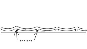

Last edited:
- Joined
- Dec 15, 2019
- Messages
- 99
- Points
- 143

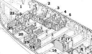
The two aftmost deck beams were still to be fitted but some work on the structures of the orlop rooms in that area remained to be done.
Three rooms would be accommodated there -- Marine Clothing, #5 in the drawing below; the Lieutenant's Store Room, #18, and the Captain's Store Room, #19 >>>
Being further inside, room #18 was tackled first. First was the forward paneled wall which I made with wooden top, bottom and side spars, but for the panels a single section of card was used.
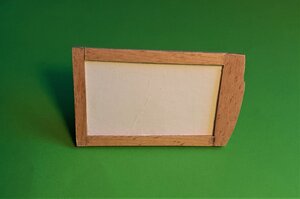
That card 'panel' was further sub-divided into 8 smaller panels by gluing on more wooden straps on each side. Just using one large piece of card for the whole wall made it easier to keep everything flat.
With the wooden straps fitted >
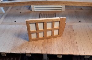
and test-fitted where it will live >
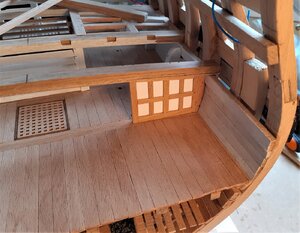
I quite liked the look of the wooden framework with the white panels, but as almost everything down there on the orlop deck was painted white, a white paint job it would be.
Here with a few other components for these orlop rooms >
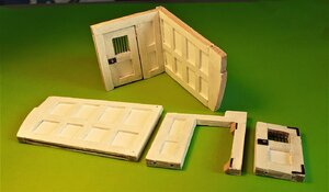
The "L" shaped section above is the Lieutenant's store room and the sections lying flat are the Captains store room still to be assembled.
(The 2 wedge shaped pieces glued to the inside face of the door standard/post above will be mentioned later.)
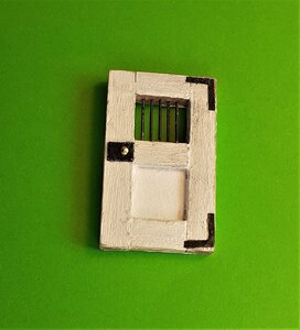
The doors, although small, were no small project! Created using a similar method as for the paneled walls but leaving the upper 'panel' empty for the bars.
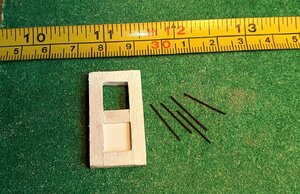
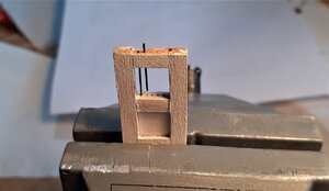
At first I attempted assembling the doors by leaving off the top beam, fitting the bars into the middle beam then trying to lower the top beam down into position while trying to get these 5 bars located in the top beam -- it wasn't working !!!
So, I glued-in the top beam, clamped the door in the vice, and inserted each bar in turn down through the top beam and into position in the middle beam. That seemed to be a much easier way of doing it. >
The "L" shaped hinges and the door lock are blackened brass, as are the 5 bars >
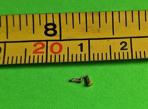
and the door knobs/handles are the heads snipped off a few brass nails >
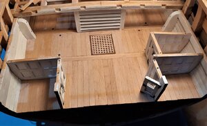
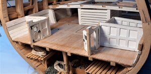
The 3 rooms positioned on the deck. (As for the wedges mentioned above ~ these were to allow me to position the door in a half open position on the Captain's store room -- I think the Captain had to rush off in a big hurry to the heads, but I'm sure he'll be back soon to lock that door.)
Dry positioned along with the as yet 'un-morticed' deck beams >
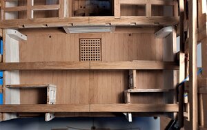
Three rooms would be accommodated there -- Marine Clothing, #5 in the drawing below; the Lieutenant's Store Room, #18, and the Captain's Store Room, #19 >>>

Being further inside, room #18 was tackled first. First was the forward paneled wall which I made with wooden top, bottom and side spars, but for the panels a single section of card was used.

That card 'panel' was further sub-divided into 8 smaller panels by gluing on more wooden straps on each side. Just using one large piece of card for the whole wall made it easier to keep everything flat.
With the wooden straps fitted >

and test-fitted where it will live >

I quite liked the look of the wooden framework with the white panels, but as almost everything down there on the orlop deck was painted white, a white paint job it would be.
Here with a few other components for these orlop rooms >

The "L" shaped section above is the Lieutenant's store room and the sections lying flat are the Captains store room still to be assembled.
(The 2 wedge shaped pieces glued to the inside face of the door standard/post above will be mentioned later.)
The doors, although small, were no small project! Created using a similar method as for the paneled walls but leaving the upper 'panel' empty for the bars.

At first I attempted assembling the doors by leaving off the top beam, fitting the bars into the middle beam then trying to lower the top beam down into position while trying to get these 5 bars located in the top beam -- it wasn't working !!!
So, I glued-in the top beam, clamped the door in the vice, and inserted each bar in turn down through the top beam and into position in the middle beam. That seemed to be a much easier way of doing it. >

The "L" shaped hinges and the door lock are blackened brass, as are the 5 bars >

and the door knobs/handles are the heads snipped off a few brass nails >

The 3 rooms positioned on the deck. (As for the wedges mentioned above ~ these were to allow me to position the door in a half open position on the Captain's store room -- I think the Captain had to rush off in a big hurry to the heads, but I'm sure he'll be back soon to lock that door.)


Dry positioned along with the as yet 'un-morticed' deck beams >

Looking very good and good progress. 
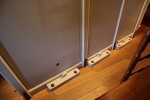
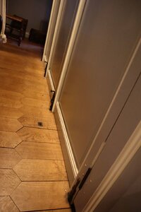
And you have to imagine, that the seamen removed all these doors when there was the signal "Ready for Action", in order to reduce the danger to get injured by wooden splinters
Such walls were all removable to have during the action free space
Take a look at these simple connections to the deck (seen at the Hermione)


- Joined
- Dec 15, 2019
- Messages
- 99
- Points
- 143

Thanks Heinrich and Uwe for the comments and the others for the likes and visits.
Uwe said "the seamen removed all these doors when there was the signal "Ready for Action", in order to reduce the danger to get injured by wooden splinters
Such walls were all removable to have during the action free space".
Would that also be the case down in the orlop deck which for most part was below the waterline?
- Joined
- Aug 2, 2019
- Messages
- 211
- Points
- 278

Hi Doc nice build sir. She is coming along and its nice seeing her come alive. 

You are Right, i guess not in the orlop Deck, but i do not know exactly. Sometimes one side Of the orlop is also out of the water, when the ship is tilted by the Wind.....Thanks Heinrich and Uwe for the comments and the others for the likes and visits.
Uwe said "the seamen removed all these doors when there was the signal "Ready for Action", in order to reduce the danger to get injured by wooden splinters
Such walls were all removable to have during the action free space".
Would that also be the case down in the orlop deck which for most part was below the waterline?
- Joined
- Dec 15, 2019
- Messages
- 99
- Points
- 143

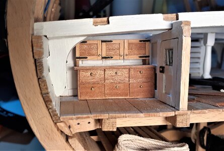
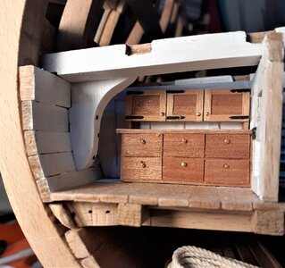
Finding information on what kind of 'furniture' occupied these rooms wasn't easy and I resorted to watching a few 'walk-thru' videos of HMS Victory on youtube to get some ideas.
Decided to make a couple of base units with 6 drawers in each -- one unit each for the Marine clothing and Captain's storage rooms.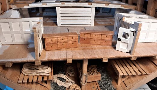
and in position where they'll live >
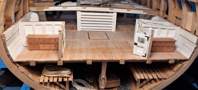
The last 2 deck beams for the lower gun deck needed fitting so, fitting these, and fitting the hanging knees came before finally gluing in the drawer units .
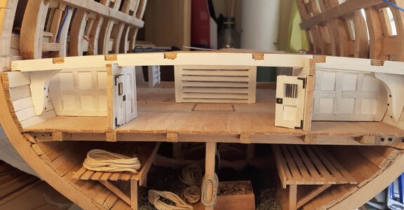
It took a couple of days before I noticed that I had omitted the central deck beam pillars! ~ that was annoying! . . . they were already turned and painted and in the box waiting their turn to be fitted at the same time as the beams. I like to attach them up into the beam and down into the floor with some wire but this time just had to be content with squeezing them into position with a little PVA, top and bottom.
Base units now permanent fixtures >
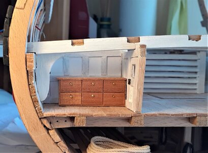
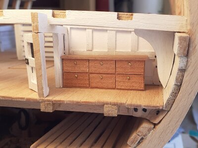
The Marine clothing room possibly had some wall cupboards, so >
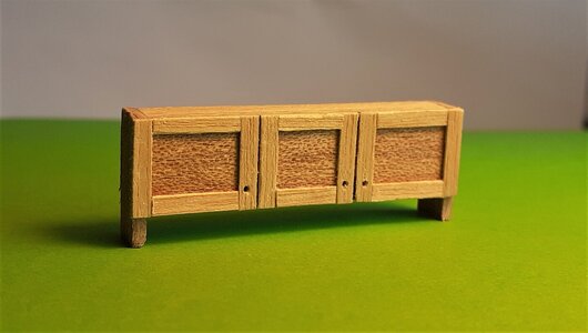
As above, drilled for handles; below, with handles made from snipped-off heads of some brass nails, as had already been used for the handles on the drawers >
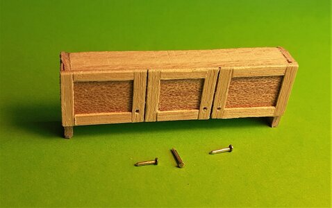
Handles fitted >
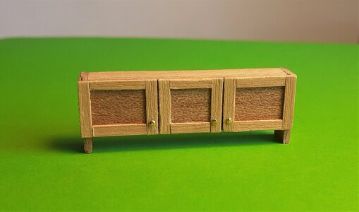
I felt these doors were a little too modern looking, 1990s maybe? . . . so I gave them some fake hinges >
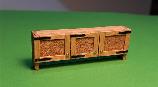
On the wall >
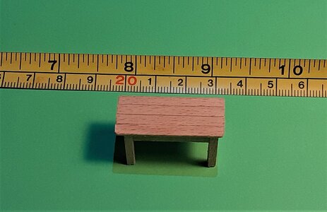
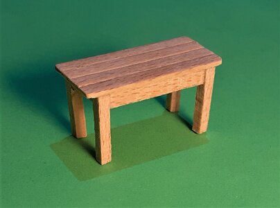
A table may have been a useful item in that room, so >
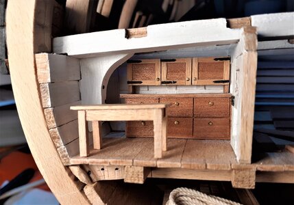
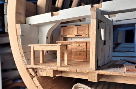
Decided to make a couple of base units with 6 drawers in each -- one unit each for the Marine clothing and Captain's storage rooms.

and in position where they'll live >

The last 2 deck beams for the lower gun deck needed fitting so, fitting these, and fitting the hanging knees came before finally gluing in the drawer units .

It took a couple of days before I noticed that I had omitted the central deck beam pillars! ~ that was annoying! . . . they were already turned and painted and in the box waiting their turn to be fitted at the same time as the beams. I like to attach them up into the beam and down into the floor with some wire but this time just had to be content with squeezing them into position with a little PVA, top and bottom.
Base units now permanent fixtures >


The Marine clothing room possibly had some wall cupboards, so >

As above, drilled for handles; below, with handles made from snipped-off heads of some brass nails, as had already been used for the handles on the drawers >

Handles fitted >

I felt these doors were a little too modern looking, 1990s maybe? . . . so I gave them some fake hinges >

On the wall >


A table may have been a useful item in that room, so >


- Joined
- Dec 15, 2019
- Messages
- 99
- Points
- 143

Thanks Shota for the comment and the others for dropping by and for the likes.
Not a lot of apparent progress to report even though what I've done has taken considerable time.
Before I progress any further on that lower gun deck I wanted to get the lanterns and their wiring installed. As the wiring for these lanterns goes through some carlings and even some deck beams, and especially at the aft end the wires go in several directions, I'm going to omit the ledges in these areas. (The deck will be completely planked anyway, so 'what's missing' won't be seen.)
Before doing any more wiring in the ship I took some time to get ahead of myself a little and created 12 of the lanterns.
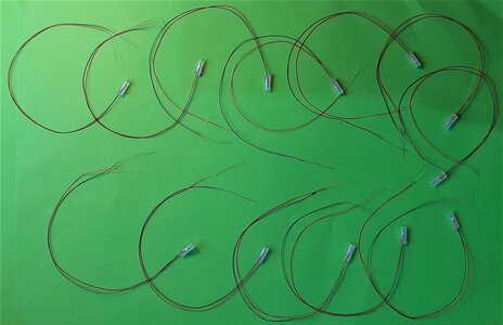
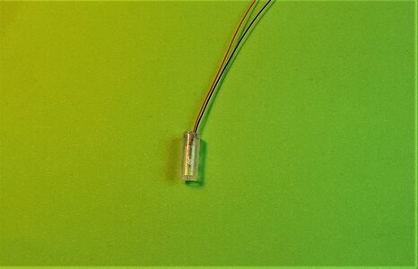
Doing what is seen above is fairly easy and quick. I just cut the tube to length, insert the LED (Pico size), lock it in position with a small drop of epoxy resin and allow the glue to dry ~~ then the 'fun' begins. Getting all the parts of the framework on to each lantern is what is time-consuming, and after a few lanterns, becomes a little tedious. (Although not in the same 'tedium league' as doing 1000s of ratlines!)
When I did the wiring for the hold I soldered the wires together in 'mid-air' -- without any kind of platform. This time I made a platform between 2 carlings and that made it much easier to solder these hair like micro wires.
The aft platform is arrowed below >
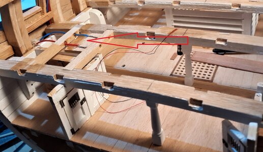
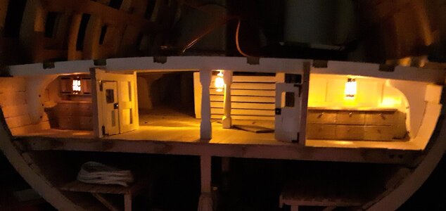
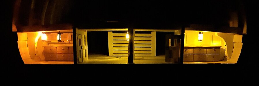
The 2 rooms at the aft end got a lantern each and I hung one near the centre in the open area of the orlop deck >
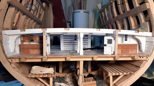
. . . and at first 'switch on' >
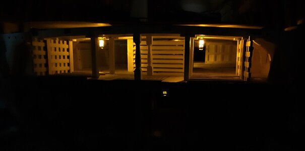
and at the fore end, illuminating the cable tiers and upper well >
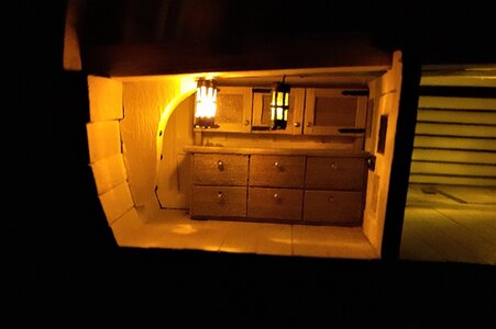
Shortly after the above photos were taken, the lantern in the Marine clothing room mysteriously became very dim, so I got one of the Marines to hang another lantern in there >
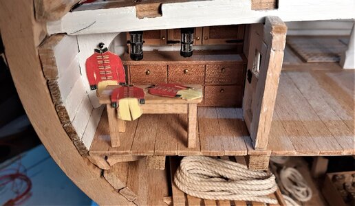
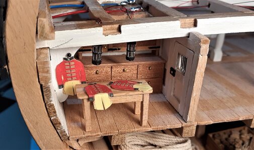
I have to apologise for the condition of that Marine clothing room ~ some tunics have been left lying on the table and another one hangs from a nail driven into a hanging knee. (Now I know why they're called 'hanging knees'!)
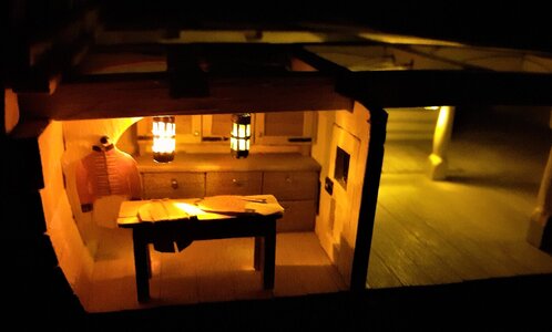
Not a lot of apparent progress to report even though what I've done has taken considerable time.
Before I progress any further on that lower gun deck I wanted to get the lanterns and their wiring installed. As the wiring for these lanterns goes through some carlings and even some deck beams, and especially at the aft end the wires go in several directions, I'm going to omit the ledges in these areas. (The deck will be completely planked anyway, so 'what's missing' won't be seen.)
Before doing any more wiring in the ship I took some time to get ahead of myself a little and created 12 of the lanterns.


Doing what is seen above is fairly easy and quick. I just cut the tube to length, insert the LED (Pico size), lock it in position with a small drop of epoxy resin and allow the glue to dry ~~ then the 'fun' begins. Getting all the parts of the framework on to each lantern is what is time-consuming, and after a few lanterns, becomes a little tedious. (Although not in the same 'tedium league' as doing 1000s of ratlines!)
When I did the wiring for the hold I soldered the wires together in 'mid-air' -- without any kind of platform. This time I made a platform between 2 carlings and that made it much easier to solder these hair like micro wires.
The aft platform is arrowed below >

The 2 rooms at the aft end got a lantern each and I hung one near the centre in the open area of the orlop deck >

. . . and at first 'switch on' >

and at the fore end, illuminating the cable tiers and upper well >

Shortly after the above photos were taken, the lantern in the Marine clothing room mysteriously became very dim, so I got one of the Marines to hang another lantern in there >


I have to apologise for the condition of that Marine clothing room ~ some tunics have been left lying on the table and another one hangs from a nail driven into a hanging knee. (Now I know why they're called 'hanging knees'!)


- Joined
- Dec 15, 2019
- Messages
- 99
- Points
- 143

With the orlop deck more or less finished, time to move up to the lower gundeck.
A whole lot of planking would have to be milled. Although quite time consuming, milling the planking was fairly straightforward, while creating the profile of the waterways was something that caused a deal of frustration for me. I've never before tried using a scraper to create a moulding and it took some time before I was 'getting the hang of it'.
At first I was trying to remove the required amount from a solid length of timber ~~ and that Beech is real hard stuff! It just wasn't happening for me.
This is the scraper I used >
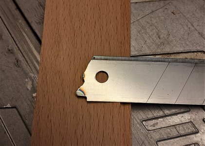
That was made from a utility knife blade. As it was proving too hard to scrape the profile from the 'solid' wood, I ran it over my table saw blade to remove most of the material >
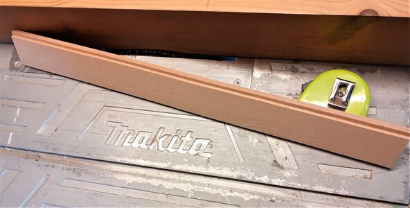
Finalised the profile with the scraper, then trimmed it down to it's final shape on the bandsaw >
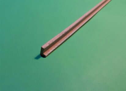
With these waterways done I could 'relax' and get on with milling the easy deck planking.
In that central area all around the main mast it's going to be quite busy with the mast, the lower ends of the posts of the topsail sheet bitts, two brake (Elm tree) pumps, four tubes for the chain pumps along with the heads of the chain pumps.
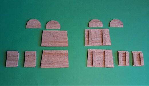
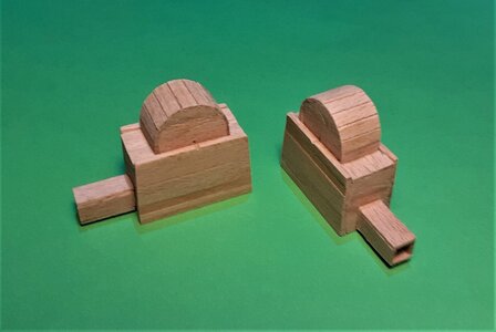
I thought "I'll just get on and make the chain pumps cistern heads." Four days later they still weren't finished!
Most of the main components >
. . . and glued up >
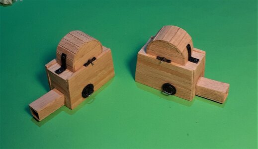
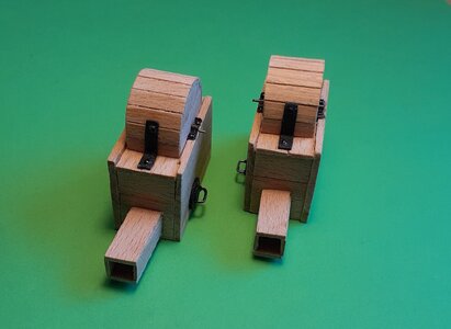
The brackets at the spindles and on the top are blackened brass but the "plugs" on the sides are card painted black with wire handles.
At this time the central area of the deck is planked as I want to be getting all that 'busy' stuff sorted. I also made a dummy upper deck beam so that I could gauge the approximate lengths of the brake pump tubes.
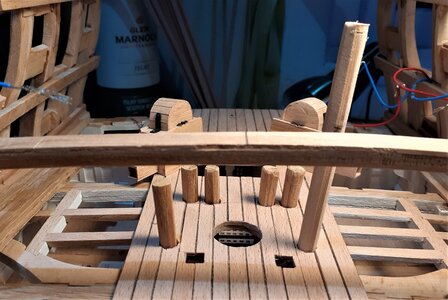
The lengths of the four chain pump tubes isn't critical as they'll be out of sight, covered by the pump head cisterns.
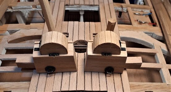
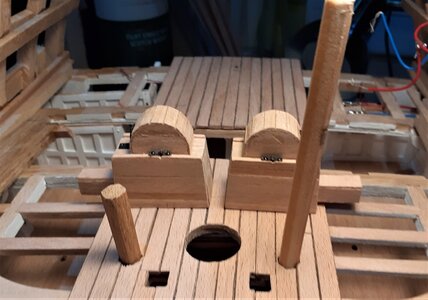
The brake pump tubes are different lengths as the one on the left of the photo above (starboard side) serves the lower gun deck and the port side tube will serve the upper deck. I've seen drawings of 3 deckers with one brake pump on lower deck and the other one two decks above on the upper gun deck.
The bottom ends of the topsail sheet bitts will be accommodated in the 2 square 'holes' ahead of the brake pumps.
A whole lot of planking would have to be milled. Although quite time consuming, milling the planking was fairly straightforward, while creating the profile of the waterways was something that caused a deal of frustration for me. I've never before tried using a scraper to create a moulding and it took some time before I was 'getting the hang of it'.
At first I was trying to remove the required amount from a solid length of timber ~~ and that Beech is real hard stuff! It just wasn't happening for me.
This is the scraper I used >

That was made from a utility knife blade. As it was proving too hard to scrape the profile from the 'solid' wood, I ran it over my table saw blade to remove most of the material >

Finalised the profile with the scraper, then trimmed it down to it's final shape on the bandsaw >

With these waterways done I could 'relax' and get on with milling the easy deck planking.
In that central area all around the main mast it's going to be quite busy with the mast, the lower ends of the posts of the topsail sheet bitts, two brake (Elm tree) pumps, four tubes for the chain pumps along with the heads of the chain pumps.
I thought "I'll just get on and make the chain pumps cistern heads." Four days later they still weren't finished!
Most of the main components >

. . . and glued up >


The brackets at the spindles and on the top are blackened brass but the "plugs" on the sides are card painted black with wire handles.
At this time the central area of the deck is planked as I want to be getting all that 'busy' stuff sorted. I also made a dummy upper deck beam so that I could gauge the approximate lengths of the brake pump tubes.

The lengths of the four chain pump tubes isn't critical as they'll be out of sight, covered by the pump head cisterns.


The brake pump tubes are different lengths as the one on the left of the photo above (starboard side) serves the lower gun deck and the port side tube will serve the upper deck. I've seen drawings of 3 deckers with one brake pump on lower deck and the other one two decks above on the upper gun deck.
The bottom ends of the topsail sheet bitts will be accommodated in the 2 square 'holes' ahead of the brake pumps.


