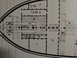
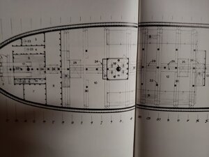
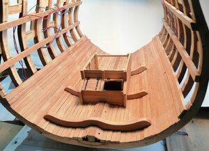
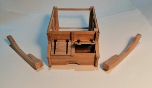
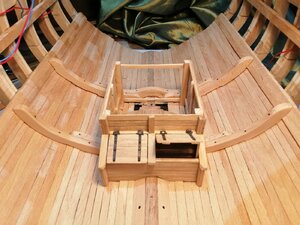
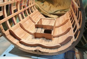
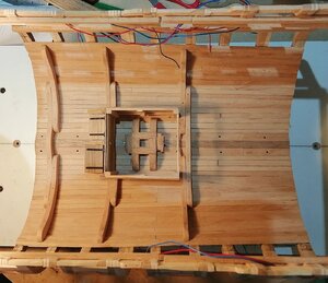
Cross Section - HMS Leopard 4th Rate 1790 - 1:44

Hi Kurt,
Just a few weeks back my knowledge of the pumps was very limited as well.

Only from my research have I found a fair amount and what seems quite a dull subject has proved to be quite fascinating.

As far as I understand from what I've found out, there appears to have been three different systems (possibly more?) for the elm tree pumps alone.
I've tried to illustrate the three types below.
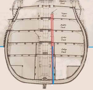
First, what appears to be the most simple system -- a direct supply >
Brake P 1.jpg
In the above drawing the water level is shown in blue; the pump tube in red. In this system the tube exited directly through the bottom of the hull and just drew sea water directly from there.

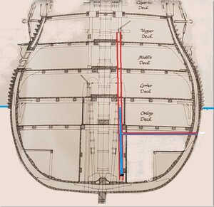
The next drawing shows what just appears to be a bit of a variation of the above. The intake pipe is situated in the hull side around 3 feet (900mm) below the waterline. I believe (although I may be wrong?) that the bottom end of the vertical tube was open above the bilges with a control valve for the purpose of occasionally flushing some clean sea water into the bilges as the bilge water would become foul and stinky. That water would then be pumped out using the chain pumps. >
Brake P 2.jpg
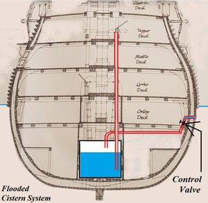
The following drawing is an approximate representation of the 'flooded cistern' system where a watertight cistern in the hold could be filled (to a desired level) by means of the pipe that exited the hullside. I understand that pipe would have a valve to control the amount of water allowed into the cistern. When the brake pump was activated it would draw water directly from that cistern.
Brake P Fl..jpg

I should say that I can't guarantee that the above info is 100% accurate but it is my understanding of what I have read in the last few weeks.

Note from these drawings above that there is a brake pump on the lower deck as well as one on two decks above, on the upper deck while the chain pumps are both on the lower deck.

While I was researching the pumps I discovered that the worst disaster to befall an English warship in home waters (and not in battle) was the result of a procedure adopted in order to carry out what should have been simple maintenance/repair to the starboard inlet pipe for the cistern on one of the biggest 1st rate ships of the 18th century.
This is an interesting read and can be found here > https://dawlishchronicles.com/the-loss-of-hms-royal-george-1782/
 
Last edited:
Hi Alex,
Thank you for your comments and to the others for the likes and visits.

Alex, you said "even a dunce beginning modeler like me" ~~~ well, if that model I see in your post is yours then you're in the wrong class! That's not the work of a 'dunce beginning modeler' ! All that framing and deck beam work is amazing. This cross section I'm doing is only my second ever model and it's the first with frames instead of bulkheads -- BUT it only has NINE frames and I know how much work that was and to get them onto the keel.
You also asked, "May I copy the idea ?" ~~~ I'd be delighted to think that anyone would copy anything that I've posted. There have been a few things on these forums that I've also copied!
If I may ask you -- you said "I am building a CAF kit of HMS Enterprise" ~~~ is that the model in the photos you have posted above?
I've never done a kit and, apart from cross section kits, I've never seen a kit of a fully framed model; I've only ever seen bulkhead models in kit form.
Hi Jim. The model in the pictures is HMS Enterprise 1:48 by CAF models, a Chinese company. The owner (Tom) is the designer of the CAF kits and is a member of SOS. He has at least two frame models, HMS Enterprise, and a bomb ketch La Salamandre, which has a lot of interior detail. He is working on a french frigate, La Renommee, but I don't know if it is available. La Salamandre is based on Boudroit's Ancre monograph, so there is a lot of material to help with the build. The Chinese kits are very well made, laser cut, on high quality wood, usually cherry, and usually include a rather complex building berth. They are much superior to anything else in the usual commercial market. CAF also has excellent customer support- Tom has sent me replacement pieces quickly. The only drawback, in my opinion and experience, is that the instructions are usually in Chinese, and not very good, so one has to do a lot of head scratching. Maybe the fact that this is my first fully framed model has something to do with my opinion of the instructions-I have a lot of questions and need guidance, but I'm finally getting it....
There are several Chinese companies in addition to CAF. There is a Chinese re-seller company, called ZHL, which has kits from other companies in addition to CAF . The owner of ZHL is Max, also a member of SOS. He is very responsive and helpful. His prices are right on as well as his customer support. He ships quickly using DHL and accepts PayPal. I just received a model of a French Xebec, Le Requin, which I ordered from Max. I will be doing a kit review in the near future. This is not from CAF. The instructions look better, and there is also a Boudroit Ancre monograph. There are several superb builds of Enterprise (Brian 077), Salamandre (Uwe's), and Le Requin (Brian077) here is SOS. I will build either La Salamandre or Le Requin next.
Cheers
Alex
 
Last edited:
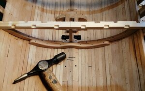
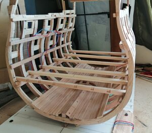
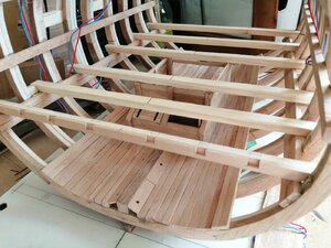
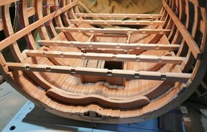
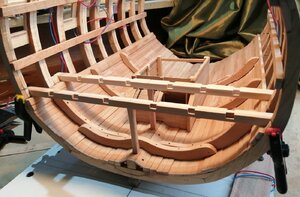
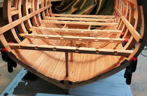
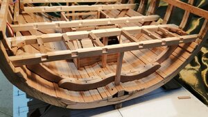
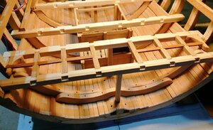
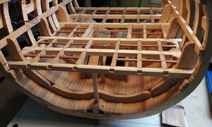
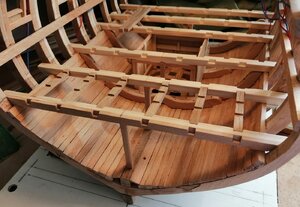
Beams: the "easy" orlop deck beams were another little project that diverted me from the hold planking.
("Easy" as they're flat with no camber
First photos of the beams that I have >

IMG_20200412_170744.jpg
IMG_20200412_171030.jpg
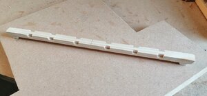
Just dry fitted above to establish their positions. Only the foremost of the beams had the mortices cut for the carlings above.
Apart from the outer facings of the two end beams, all others were made from softwood as I tried to stretch out my dwindling supply of beech -- the lockdown continues and still no timber merchants open.
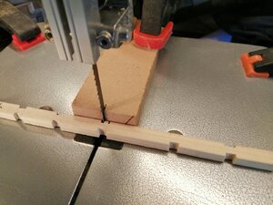
The mortices in that beam were cut by a 3mm chisel and when I continued to try cutting the mortices in the softwood beams they weren't cutting as cleanly as I wanted, so I began cutting them on the bandsaw with a stop block clamped round and behind the blade to control the depth of cut.
IMG_20200415_145403.jpg
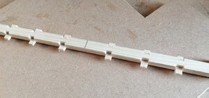
Of course, using the bandsaw cuts all the way down, so I had to glue in fillers at the bottom of each cut >
Beam Mortices-.jpg
Cutting off the excess 'bits' and sanding down and the mortices look OK .
Beam Mortices--.jpg
And back in the section for another dry fit before going in 'the box'.
Beams - Orlop..jpg

Beams - Orlop.jpg
 
Cutting off the excess 'bits' and sanding down and the mortices look OK .
Beam Mortices--.jpg
Nice result!
 
They look great especially the low angle, have you tested both woods with your finish to see if there is much difference in appearance?
 
Beams: the "easy" orlop deck beams were another little project that diverted me from the hold planking.
("Easy" as they're flat with no camber
First photos of the beams that I have >

View attachment 152817
View attachment 152818
Just dry fitted above to establish their positions. Only the foremost of the beams had the mortices cut for the carlings above.
Apart from the outer facings of the two end beams, all others were made from softwood as I tried to stretch out my dwindling supply of beech -- the lockdown continues and still no timber merchants open.
The mortices in that beam were cut by a 3mm chisel and when I continued to try cutting the mortices in the softwood beams they weren't cutting as cleanly as I wanted, so I began cutting them on the bandsaw with a stop block clamped round and behind the blade to control the depth of cut.
View attachment 152819
Of course, using the bandsaw cuts all the way down, so I had to glue in fillers at the bottom of each cut >
View attachment 152820
Cutting off the excess 'bits' and sanding down and the mortices look OK .
View attachment 152821
And back in the section for another dry fit before going in 'the box'.
View attachment 152822

View attachment 152823
Bandsaw stop block is brilliant. Great project and I will follow your completion log.
 
Hey Jim,
The orlop deck beams look great. You've proven the old adage that there's more then one way to skin a cat. Just in case you need reference for the pillars in the hold I'll attach a few photos.20200522_203704.jpg20200522_203854.jpg20200522_203918.jpg
 
Jim
Wow, ! This is a very impressive build, and the step-by-step practicum is explained and illustrated so well that even a dunce beginning modeler like me can understand it. I am learning a lot from your process and from all of your inventions and tricks. I especially like your milling jigs, and your drawn-out cannon are genial. May I copy the idea ? I am building a CAF kit of HMS Enterprise and your build will be immensely helpful. I've bookmarked it....
We have something in common: Earlier in my build, I thought I had totally misplaced the main deck deck-clamps, but it turned out that my plans had two lines, one marking the finished deck height, and another the top of the deck clamp-the problem was that the lines were unmarked...Thankfully, I had placed my deck clamps at the correct level, so I did not have to tear them out. However, I had totally misplaced the level of the foredeck clamps- A couple of days ago, I cut them out (they had been glued and trunneled, so it was tedious to do ) and carefully and re-positioned them. Anyway, thanks a lot and Congratulations. !
AlexView attachment 151372
Here are the foredeck clamps. There are two per side-the lower one was placed initially, and the second one on top- but still not at the correct level. (long embarrassing explanation as to why I did that.)

View attachment 151374 この画像は、再配置された前デッキデッキクランプを示しています。下部デッキクランプが部分的に削除されました。デッキビームと構造物の中心に使用しているレーザーポインターに注意してください。
[/見積もり]
s素晴らしい。
 
Thanks Eric, Kurt, Ian, Raymond and Fukui for your comments and information and to the others for the likes and visits.

Kurt ~ on my other build, apart from the black painted wales and a few other small parts, I didn't use any sealers, varnishes, paints, colourings, stains or waxes/polishes but just left the wood in its own natural colours and I expect I'll be doing the same with this build as well. In a couple of the photos in my previous post above (#24) the beams appear to be very pale white -- but they're not nearly as pale as these photos suggest -- it is just the effect of taking the photos in different lighting conditions. Anyway, these beams and the carlings and ledges that will follow won't be seen later - except possibly by the 'little people' who may walk through the hold while looking upwards!

Raymond, thank you for the drawings. I should say that this build won't be 100% accurate because, as far as I know, there does not exist 100% complete drawing and plans of any 50 gun ship. In particular, there is virtually no information relating to the hold area and very scant information about the orlop deck so what I'll be doing especially in these areas is something of a guessing game but largely based on what I see on other build logs of English ships of the same era -- and I DO look at a lot of other build logs!
 
In my earlier post (#24) the beams are shown with the mortices cut for the carlings. The beams shown there are only dry fitted so I'm waiting until they're glued in before cutting any carlings. Before the beams are made permanent there are a few things still to be made and fitted . . . and, in the main, these things are the riders. I have virtually no information about riders in the 50 Gun Book nor in any of the drawings except 2 fairly vague hints at these.
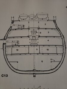
In the section drawing I included in my opening post of this thread the 'rider' appears to be a single piece. These riders comprised of at least 5 sections and in some cases more than 5.
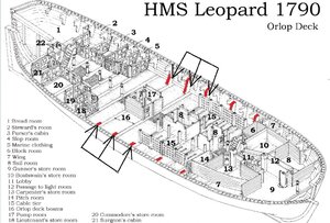
Nothing is shown of their exact position, but from one single drawing of the orlop deck it appears that there may have been 5 riders in these 4th rate ships.
In this drawing I have indicated in red what appears to be 5 riders. Only the 3 that I have arrowed should occur in the section I'm building.

Orlop - riders.jpg

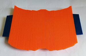
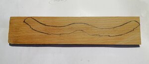
Getting the correct profile of the riders to fit the floor provided some 'fun'. I made a few attempts with card before I was getting close, then I bought this .

Profile gauge.jpg

That made it a fair bit easier to get close to the profile, transferred to card and tweaked until it was good enough to transfer to the wood before the bandsaw did the cutting out.

Rider draft.jpg
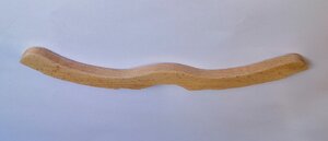
The first of the floor riders >
Rider aft-.jpg
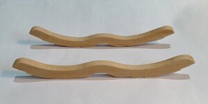
That one above is the aftmost of the 3 riders. Here it is with the foremost of the 3 >
Riders-floor.jpg

Here, the 3 floor riders go for a test ride >

Riders -floor -.jpg

In the drawing there appears to be a rider just a little ahead of the main mast. That's the middle one in the photo above. For that one I cheated a little. That one would appear to have to pass right through the shot locked, so instead of making a complete floor rider for there, I made it in 2 parts.
It's shown below with the first futtock riders on each side >

Rider S Locker-.jpg

Here with the aftmost rider . . . both with their first futtock riders >
Aft - Mid riders-.jpg

. . . and all three with their futtock riders get a final test ride before being fitted permanently >
Riders...jpg
Riders..jpg

Well, can't put off fitting them any longer as I can't get on with the orlop beams until they're in position.

Aftmost rider glued and nailed. (In this photo the deck beam was only clamped in position to help position the rider) >
Riders - Nails.jpg

Riders and beams get to meet each other - - beams still just dry fitted at this stage (still have to make the support pillars for these beams) >


Riders Beams..jpg

Will have to wait until the inner hull planking of the orlop deck is done before I can complete the (upper) breadth riders.
 
The work is great, and research is well done.

I really like the cross section builds as it give a look inside the ships most modelers don't see.

Before I started the Blandford build cross section, I had never heard about well houses or shot lockers in a wooden ship.
 
The work is great, and research is well done.

I really like the cross section builds as it give a look inside the ships most modelers don't see.

Before I started the Blandford build cross section, I had never heard about well houses or shot lockers in a wooden ship.

Hi Kurt,

Doing this cross section has sure opened up a whole lot of new challenges that I didn't have on my bulkhead build!

An update:

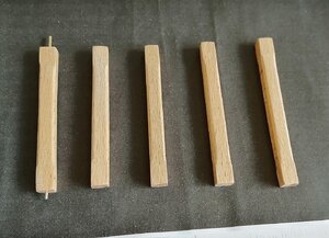
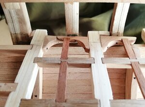
Orlop deck beam pillars. These were fairly straightforward as they're basically square in section with just a stopped chamfer on each corner.

Hold Pillar...jpg
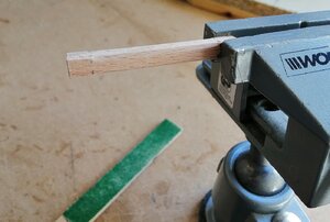
Just held each one in the vice and used a sanding stick to obtain the chamfers.
Hold Pillar.jpg
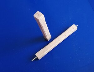
To help keep each pillar in its position under the beam and on top of the keelson I drilled a 1mm hole in the centre of each end as well as under the beam and down into the keelson. A short piece of 1mm brass wire kept everything in line.
Hold Pillar..jpg
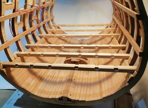
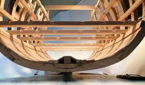
First couple of beams fixed.
Fixed beams 2.jpg
Then six.
Fixed beams 6.jpg

Six beams but only five pillars ~~ the shot locker/well took care of the pillar for that beam.
Beam C..jpg

This is the first time I have arrived at the challenge of proper deck beams, as my other build only had very basic beams and anything that resembled carlings only occurred where there were hatches or companionways. I didn't have to do ledges or knees either. Now, at this level, the orlop deck, I want to use it as a bit of a test bed and although virtually all the deck will be covered with nothing of the beams, carlings etc. visible, I still want to "have fun" attempting these.

The photo above shows carlings between these first two beams. The next photo shows the ledges and my first attempt at lodging knees.
Beam C L ...jpg
The "hole" in the middle without a ledge is for a future grating.

A couple of little mistakes in there, and I'm not sure I got the correct proportions of the knees, so I'll have to sharpen up and do some more homework . . . . .
 
Hey Doc,
Everything looks great. I admire that can-do attitude of yours. When I was a kid, prior to jumping into a swimming pool, I would dip my toe in the water to see if it was tolerable. Your dedication to trying something new such as carlings, ledges hanging and bracing knees allows a person to see if full scratch builds is a tolerable endeavour.

Raymond
 
Doc, have you looked at the plans and builds in the Blandford group.

It is a training scratch build project to show how to make all the frames, beams and other parts of real ship structure.

Full of knees and carlings and other such stuff.
 
Thanks Raymond and Kurt for the comments and the others for likes and visits.

Kurt, I've been having a look around the Blandford section as you suggested. It was just a little difficult as it's reduced to half of the page width as on the 'regular' forum here, and I'm only allowed to view the small photos but not the enlarged ones.

A little update.

Pressed on with the carlings and ledges. Previously I had decided that I would wait until the inner orlop hull planking was done before finishing the riders. I changed my mind and went ahead and fitted the remaining upper breadth riders first.

Breadth Riders.jpg
I plan to fit the inner hull planking between the riders. Yes, that wouldn't have been done that way on the real ship, but this isn't a real ship. I'm sure it will work for me this way as I feel it would be really tricky getting the correct profile on the riders as it's getting a bit busy now for doing intricate things in among all these deck beams, carlings and ledges.
As far as I can ascertain, there are no hanging knees for the orlop deck, only lodging knees. It didn't look possible to fit a knee to the far side of the third beam (looking at it in the photo above) as the mid rider is adjacent to that face of the beam, so I had a go at making opposing knees for that beam and for the second beam in the photo.
Opposed knees.jpg

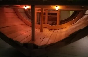
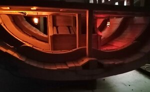
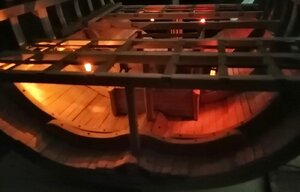
At this point, before the deck planking starts to cover the deck, I wanted to get the lanterns for the hold in position. This job proved more than tricky enough and would have been impossible (at least for me) to have tried with the deck planking in position.
I used the milling machine to run grooves in the carlings in the two rear sections as I chose the easier (if incorrect) method of fitting the ledges. I chose just to run full length ledges in this area. (It will eventually be completely covered by the planking.)
Carlings.jpg
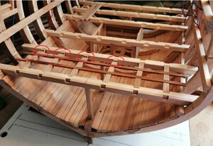
In the next photo I've circled the 4 'extra' grooves in the carlings. These are for the wiring leading to the aft hold lanterns.
Carlings - cut-outs.jpg
I'm planning on having 8 or 10 lanterns in the aft part of the section and probably 8 in the fore end.
I understand that each 3 volt supply can illuminate 10 led lights, so the fore and aft lights will be on separate circuits.
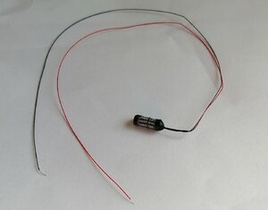
Only made four lanterns so far. Made from clear tube with the led held in by a spot of glue, black paper glued on to simulate the framework of the lanterns.
Lantern.-.jpg
I checked and double checked that each one was working before committing them to their places, because once they're in, they're in -- no going back, and when the planking is on it will be impossible to replace them. Those wires on these led lights are not much thicker than a human hair and are a nightmare to work with.

The aft lanterns.
Hold lamps.jpg

The fore lanterns.

Lanterns fore.jpg

. . . and the 'four' lanterns.
Lanterns 4..jpg
 
Hi Thomas,

Thanks for your very flattering comment - - although I feel I can't fully agree with "excellent craftsmanship".
I do see on this forum and others, what I consider to be almost unbelievable workmanship and I know my attempts are just not in the same league. That's not modesty talking -- it's reality!
Having said that, I'm not disappointed with what I do and I can live quite happily with the standard I'm at.

Nevertheless, it's very encouraging to read comments like yours! Again, thank you!
 
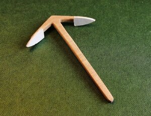
As there are no details of what populates the hold, I tend to snoop around other build logs looking for ideas. I already have a few barrels and some 'rope' and timber that may be able to be used. On one build log I spotted an anchor lashed to one of the pillars, so that seemed feasible.
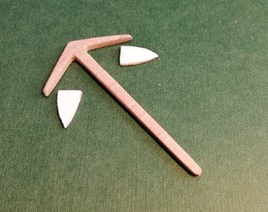
On my other build it hadn't occurred to me to make my own anchors so this was another new small venture. Not having any suitable brass I opted for wood. I laminated about 7 layers of 0.6mm veneer at different angles to create a 'chunk' out of which I could cut an anchor blank.
The blank. The flukes I made from 3 layers of card glued up and cut to shape.
A. blanks.jpg

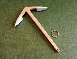
Flukes glued on.
A. Flukes.jpg

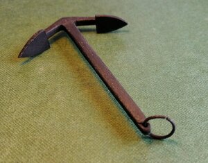
The only metal part is the ring made from 1mm brass wire.
A. F - R.jpg

Some black acrylic paint and it was looking a little like an anchor.
A. B - R.jpg

Now, it's looking for a pillar . . . . .

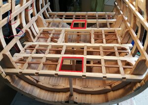
Back in post #33 above I mentioned grating. Looking at the drawing of the orlop deck in the book I didn't really understand why it looked different to the deck planking arrangement for the gun decks above. Only by 'snooping' around other logs did I see the non-secured, lift-out planks on the orlop. That has required me to slightly alter the deck beams I already have in place in order to accommodate the lift-out planking. In the meantime, I decided on two gratings for the orlop deck. These will be in the locations shown in red below.
Gratings...jpg

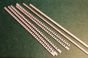
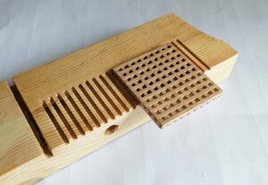
The 2mm cutter in the milling machine cut the 'notches' in the 2mm thick stock.
IMG_20200618_213238.jpg

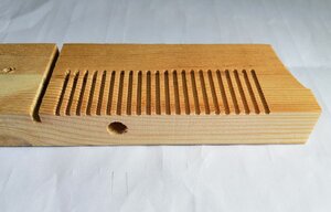
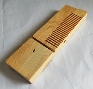
I needed some kind of device to maintain a constant distance between the strips during glue-up. The "teeth" would only keep the required distance in one direction so I again used the mill to create a jig in which the gratings could be glued.
(The big hole and deep groove mean nothing -- they were already in the piece of wood.)

Grating comb...jpg
Grating comb..jpg

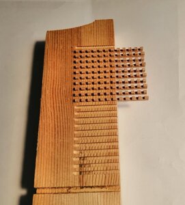
With the 'toothed' strips in place.
Grating comb.jpg

and the first completed grating.
Grating comb....jpg

For now, the gratings will have to stay in the box until I can establish the final level of the deck and get the coamings made and fitted.
 
Back
Top