Cutty Sark Semi Kit 1/40 Prototype

Joined
Dec 15, 2023
Messages
111
Points
103

A few months ago I had a request to design and build a prototype of Semi Kit of this Ship for a client in the UK.
How did I get this job? I worked on this ships restoration in 2010/11 and was tasked with taking all the measurements, scan data and photos of her without planking at times and building a digital model of her exterior and structure to exact as built specifications, the result is like an Anatomy of the ship book.


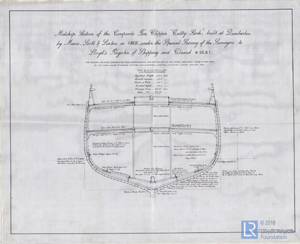
All the plans that exist today are educated guesses based on crude measurements due to the period or based of earlier plans , so a lot of inherited mistakes have crept into the plans, I have studied all the plans I know of and then tried to wipe all that and start with what is known and verified from the ship, and its really an eye opener as to how much crucial info is off.
The Cutty Sarks hull was laser scanned in 2009 to provide the architects who designed her current enclosure with a firm guide as to her hull form, and when this is rebuilt using naval Architects techniques and lofted in Nurbs software and faired the error is only very small about 10mm at most full size, the only lines plan that has the midship correct for example is C Jordans midship 1922, but even his sheer line is off aft.
The sagging and collapse of Cutty Sarks hull has been factored into this as it was during the restoration.
I could do a whole post on which plans have what issues and back it up with photographic evidence on every count but I am not prepared to do this publicly.
The official Plans from the Cutty Sark .Org are also approximate even by there own admission, they are based on recollections and previous plans.
What surprised me the most is I have owned C Nepean Longridges book most of my life and viewed it as the bible but after working on the ship and measuring it first hand it's far from it, I am perplexed how some of the measurements are so far out, I can only assume some of the things he measured have been replaced to different scantlings from when she was afloat as a training ship.
In saying all of this how many modellers really care about absolute accuracy? and just want to have fun, I personally could not go and spend over $1000 on a kit that has out of scale planking, wrong lines and even the waterline in the wrong place, the AL kit is the worst, it's not on in my opinion.

I am going to do some plans based off the scan and you will be able to see for yourselves. I am just sectioning the scan, no interpretation is required, it's absolute

I am wanting to know if anyone out there is interested in this kit as I plan to do a small run of this.

I will start this blog with images of the CAD model and showing it overlaid over a version of the scan mesh
But first the size of the model and the height relative to a standard sized room
Size Table.jpg
A couple of shots of the cad model and scan overlaid.
Fore_end.jpg
Aft End.jpg
And lines compared to the sections of the laser scan.
Aft lines.jpg
Fore_lines.jpg
 
Some shots of the Model Backbone structure
Stern
Stern.jpg

Fore endStem.jpg
Frames dry fitted to keel and deck base dry fitted.
DSCN9642.JPG
The deck notched in to frames heads.
DSCN9643.JPG
and 3 more showing the deck longitudinals forward, the aft saloon and rabbet being carved.
girders.jpg
Saloon.jpg
And rabbet being carved today
DSCN9646.JPG
Plank test fit
DSCN9647.JPG
 
Starting to fit last frames...only 3 to go.., saloon interior and break of poop.
The plywood part that sits on the frames and forms the Saloon floor is a 2 layer component, the second later not shown has all the formers for the counter bulwark in it taking it up to the poop deck height.
The Saloon is able to be seen through the skylight and or companion doors if left open

DSCN9670.JPG

DSCN9669.JPG
 
Thanks Peter
It all started quite accidently really, I was doing a set of plans of her anyway and once the restoration really got under way I was asking for measurements and photos from them and they gave me the scan data and I was giving the plans to mark on, in the end the plans were being used to record it all, and with the hull being stripped bare it was very easy to do.
I have attached a couple of examples of the detail of the data collected, one of when I was resolving the forward deadwood and one where I asked for the widths of the stem post.
Initially they were doing the drawings in Excel, which is not ideal but non draftsman quite often do use that for some reason.
On top of that a few private sets of Photos have been of great help, Thanks Kevin!.


keelson.jpg

Stem width.jpg
 
I would like to show this image as well as it shows the the state of the sound frames as well as the rise of floor as opposed to the Proposed Rennie midship which has a completely different shape and turn down to the keel.
The Midship frame is back in the dark where the workers are and the frames are a subtle curve.
This shot was taken near the level of the forehatch looking aft on Stbd Side, the notches in the bed coincide with the foremast heel
IMG_3850.jpg

As opposed to the wasted frames here.
_MG_0755.jpg and here
IMG_4959.jpg

Here is another very interesting shot which shows the construction of the stern very nicely, note the way the rabbet turns into the overhang of the counter and the oxter plates are placed either side of sternpost head to provide firm fixing for the planks in this area as well as lateral reinforcement for the rudder head should it come away.
IMG_4337.jpg
 
Last edited:
Another note about the models scale, things like the decorative panelling throughout the ship are near impossible to do any smaller.
Here is the CAD model of the forward deckhouse as fitted on Cutty Sark
It's done in 3 layers as is the real thing. the base layer of cherry 2mm thick in dark brown and the second layer done in .8mm thick stock.
7mmlayer.thumb.jpg.4dfa5a348abcde0da2677e8c35f92d26.jpg
Then the last layer of .5mm is done. also the round mouldings which are cut on CNC an be glued in at this point, each layer needs to be stained and sealed before the next is done. A very tricky job even at 1/40.
At bottom is a jpg of this at full size if you which to see how small this is in reality, print at 100%
mouldings.thumb.jpg.c7f1ca8e72e17dd656297643b6231415.jpg

Cabin size.jpg
 
Thanks Peter
I guess it comes from being a stickler for details, I am a professional full time 3d artist/modeller in games and film which I have been doing for nearly 20 years so it all helps, I work for a studio called Plastic Wax in Sydney.

I can finally show a dry fitted frame almost complete.

Of course this is all just leaning together right now and parts are missing but its the bulk.
The Foredeck housed into the heads, the forward end gets housed into slots in the knightheads, leaving the underside clear for styrene framing as per the actual ship. Note this is a standin Fore deck the actual is laminated over a form from 2 layers of .4mm ply to make sure the camber and fore and aft sheer is in the deck and needs no force to shape.
DSCN9675.JPG
Details of the Poop construction.
DSCN9676.JPG
Note the stern rabbet
DSCN9671.JPG

The slots for the counter cant frames.
The variance in steps in the counter parts are deliberate and its designed to forma definite seat for the counter bulwark ply sheet so it sits in a rebate.
The 1mm ply poop deck is actually laminated from 2 layers but only one is shown on the model here.
DSCN9673.JPG
A nice shot of the frames and Rabbet
DSCN9677.JPG
The main deck joins came up ok.
DSCN9678.JPG
 
Last edited:
I would like to ask for some preferences, I have some interest now in this semi kit and I want to consult with potential users or anyone watching about material for the bulwarks.
What I can tell you is in the ship they are made in sections and riveted to butt straps which in turn are the locations of the bulwark stays.
The bulwark is .5mm thick and planned to be made from .5mm aircraft ply with the grain vertical, the butt straps are to be brass so the stays can be soldered to them first, essentially the stays and butt straps get mounted to the model first and then the plating is glued on in pre-cut sections.
I would like to know if anyone has other suggestions for this material, but not brass, I don't have the capacity to make large brass parts, of course nothing is stopping someone from doing this using the ply parts as patterns, but as some of you know .5mm ply is VERY expensive, a 1200mm x 1200mm sheet is $100 AU.
In the below shot the bulwark plates go the extent of every second bulwark stay so the unsupported span is a little less than the stay spacing which on the model is only about 34mm
IMG_8222.jpg
Here is the arrangement on the model, the yellow selected part is a full plate, it has a 3mm overlap with the sheer plate which protrudes above the deck at a constantly changing height.

ViewCapture20231228_110100.jpg
A section of its construction in the model.
ViewCapture20231228_111249.jpg
So options
.5mm ply with brass Butt straps, plates would need to be sealed before installation to remove grain.
.7mm laminate (formica) as used on bench tops and joinery, very strong but needs filling and work on one side to make it usable.
Styrene too soft for a structural part unsupported
I do have a lot of .5mm aluminium to in full 2400 x 1200 sheets
Any ideas?
 
Last edited:
I would like to ask for some preferences, I have some interest now in this semi kit and I want to consult with potential users or anyone watching about material for the bulwarks.
What I can tell you is in the ship they are made in sections and riveted to butt straps which in turn are the locations of the bulwark stays.
The bulwark is .5mm thick and planned to be made from .5mm aircraft ply with the grain vertical, the butt straps are to be brass so the stays can be soldered to them first, essentially the stays and butt straps get mounted to the model first and then the plating is glued on in pre-cut sections.
I would like to know if anyone has other suggestions for this material, but not brass, I don't have the capacity to make large brass parts, of course nothing is stopping someone from doing this using the ply parts as patterns, but as some of you know .5mm ply is VERY expensive, a 1200mm x 1200mm sheet is $100 AU.
In the below shot the bulwark plates go the extent of every second bulwark stay so the unsupported span is a little less than the stay spacing which on the model is only about 34mm
View attachment 416823
Here is the arrangement on the model, the yellow selected part is a full plate, it has a 3mm overlap with the sheer plate which protrudes above the deck at a constantly changing height.

View attachment 416824
A section of its construction in the model.
View attachment 416825
So options
.5mm ply with brass Butt straps, plates would need to be sealed before installation to remove grain.
.7mm laminate (formica) as used on bench tops and joinery, very strong but needs filling and work on one side to make it usable.
Styrene too soft for a structural part unsupported
I do have a lot of .5mm aluminium to in full 2400 x 1200 sheets
Any ideas?
Hi Richard, I would like to help you but , I can't understand the problem (translator). Frank
 
Hi Frank
I am asking for other material suggestions for the bulwarks aside from what is listed and not brass.
 
Hi Frank
I am asking for other material suggestions for the bulwarks aside from what is listed and not brass.
I would suggest an aluminum sheet, it is very easy to form and process, but...if you need to solder wire or other parts, you will fail, only glue is an option...
 
Thanks guys

You are correct in that assumption Jim, there is absolutely nothing that needs to be soldered to them and those that do need fixing have enough area to CA on.
The only small fitting which needs to carry load are the boomkins and those can be pinned through.
Looks like I will be experimenting with milling aluminium on the CNC soon.

On another note I am playing with the idea of publishing this as a set of plans and templates that can be replicated at various scales to meet increasing demand for smaller scales.
What I am proposing will cost a little more than regular set of plans for the simple fact it will not be done on paper, the reason is paper moves.
I hope you all know this but you should never print on paper.
Plans should always be printed on drafting film, it is stable, semi transparent and heavy gauge making it tough and ideal for cutting with a knife and running a pencil around it.
film.jpg The other huge advantage some of you may not realise is the ink used on film is almost like a wax and if ironed face down will transfer on to the wood

It can be shipped anywhere regardless of climate and it will not move.
The bonus of this is I don't have to limit you to my choices of timber although I am adamant of this personally, Anigre for decking as it looks identical to aged teak and American Cherry stained with golden yellow stain to replicate the golden brown of varnished teak.
But ultimately its up to you. Can I have some thoughts on this.
an example of this would be the frames and keel, I would provide each frame as a normal profile with the bevel also marked on it so it can be glued onto the ply cut out and bevelled with a file.
This was done in the same way before I owned a CNC and with care note the quality of the fits.
623234.jpg.736b1ed5d76712fa2437c33ca0f42f20.jpg622813.jpg.bd51d887903286fa698a758793ddcbaf.jpg

The keel would be the same with the addition of 1:1sections at every frame and waterline, of the rabbet on a separate sheet that can be cut up.
rather than the frame notches being marked on keel I would mark the location of one side of the frame, to allow for users to supply a different thickness of frame, something along that line of approach
The accuracy of the model will not be compromised in any way, it's still as close as a shrunken version of the full size thing but users will just have to be good at scroll sawing and cleaning up to the very fine lines which will be very fine lines indeed .13mm or finer.
I would not think that anything smaller than 1/64 could be built to the proper level of detail, things would have to be dropped or scaled up to make it possible. though.
I would include plans for everything on the hull and masting, including the decking and planking and optional cast resin fittings.

Or am I stupid doing this and better off just doing proper plans of the ship at every level and letting you build your own and come up with you own construction method.


Can I have some thoughts on this from everyone?
 
Last edited:
All I can say is WOW! I first built the Revell Cutty Sark back in the early 1960s or so when I was a young teen. That spurred my interest in tall ships and at age 73 that interest hasn't waned. My wife and I visited the 1:1 scale Cutty in Greenwich and as she hove into view, I was literally in tears.
Big disillusionment... I hadn't realized how much of her was and is iron! I had always assumed tall ship = wooden ship. Once I saw that this wasn't the case, it made perfect sense.
I have no desire to make such a complex model as yours, but I look forward to following this fascinating thread.
 
Back
Top