Not my problem thankfully but I could display it in my homes hallway, many new homes here have wide halls now, just need to swing the yards around a bit as the yard length is really the biggest issue with size, height and length are not reallyGreat work Richard. My others half first comment was "And where exactly would you put a model that size?" ... I did respond "Mere detail".
-

Win a Free Custom Engraved Brass Coin!!!
As a way to introduce our brass coins to the community, we will raffle off a free coin during the month of August. Follow link ABOVE for instructions for entering.
-

PRE-ORDER SHIPS IN SCALE TODAY!
The beloved Ships in Scale Magazine is back and charting a new course for 2026!
Discover new skills, new techniques, and new inspirations in every issue.
NOTE THAT OUR FIRST ISSUE WILL BE JAN/FEB 2026
You are using an out of date browser. It may not display this or other websites correctly.
You should upgrade or use an alternative browser.
You should upgrade or use an alternative browser.
Cutty Sark Semi Kit 1/40 Prototype
- Thread starter RichardHDunn
- Start date
- Watchers 31
You had to be from up that way somewhere. I knew a few Mainiacs back in the day in Massachusetts.I am from Maine…a common Maine saying…as in “That pizza is wicked good!” South Boston is a bunch of flat landers!
From the great looks of that model I'd say the beer is mostly empty as opposed to mostly full. Ha! Good start with that Richard so why not finish it? You are certainly making a name for yourself and I for one see that you deserve it. Bigger is always better I think. So what is your main project?This is a prototype for a kit I have been asked to do, I may not take it beyond the planking stage, it depends if I get the bug.
But on the note of size its tiny compared to my main project.
I put the beer on the deck as most people can relate the scale from that.
View attachment 417706
TEV Wahine 1/35 Large Scale RC build
I have been building this model for 2-3 years now and had a build on another site but due to requests I have decided to do a build of sorts on here as well but will spend some time just getting everyone up to speed as its a complex build and lots to grasp. This is not for the faint hearted...shipsofscale.com
The Wahine, the one with the beer I am holding is my main project, I wasn't saying that's tiny... I am not totally loopy...So what is your main project?
I built Cutty Sark as a kid from the longridge book but plank on frame, this is a job for a customer not sure I would ever finish it, but I will plank it and the decks and see what happens.
It's an easyish plank apart from stern, no stealers and apart from a wider garboard its just evenly divided girths and full length strakes
Last edited:
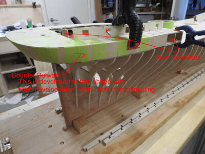
Ok I am devoid of some nautical terms so: What part is the 'plate'? Which are the 'counter bulwarks' and which are the 'counter frames'? I may as well get involved now as I'm sure I'll be asking you later.Some more progress today
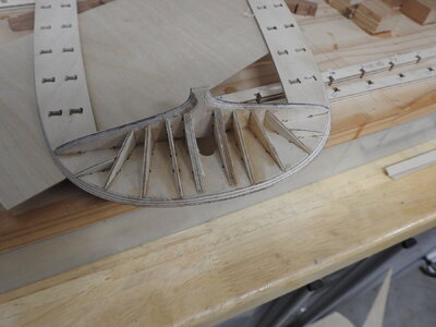
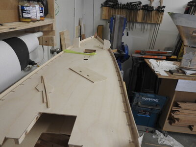
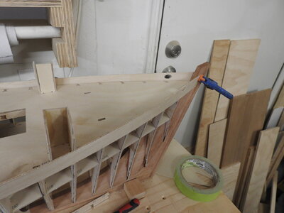
The tween decks forward are dry fitted. luckily Cuttys Tween deck is parallel to the main deck and therefore the tween deck can be held down with lots of 37mm sticks wedged in under the main deck beams,
View attachment 417975View attachment 417976
And just to demonstrate the plate development, the counter bulwark dry fitted and taped into position on the counter frames
View attachment 417989View attachment 417990
View attachment 417991
I have the rabbet on the Port side of the aft half of the keel/sternpost to do and the aft frames to bevel and its ready for final glued assembly
Ok, I see. Do you have a build posted for the Wahine? I'd like to see more of how you built it if It's available. It sure is my kind of size. Can you make a kit of it? I think your into an era where nobody else is making any kits at all. It would be nice if a few were available in this large scale. If I made one I'd have to give it to a museum I suppose. NorgaleThe Wahine, the one with the beer I am holding is my main project, I wasn't saying that's tiny... I am not totally loopy...
I built Cutty Sark as a kid from the longridge book but plank on frame, this is a job for a customer not sure I would ever finish it, but I will plank it and the decks and see what happens.
It's an easyish plank apart from stern, no stealers and apart from a wider garboard its just even full length strakes
The Wahine build link is right under the photo and yes it's in this site now, I am gradually bringing it up to date
I appreciate all the information here Richard. I am just really excited about this large scale model. Thanks. Pete
Every time I hear large scale I cringe.....I need to reprogram my brain.. this is not large to me the hull is only 1.6m.
I will get their in time.
I do realise it's my perception that is wrong don't worry..
This is the same hull at the same scale, If you still call this large then I will fold and submit.....
This was done on CNC but scrapped for various reasons

I will get their in time.
I do realise it's my perception that is wrong don't worry..
This is the same hull at the same scale, If you still call this large then I will fold and submit.....
This was done on CNC but scrapped for various reasons

Last edited:
A shot of the fore and aft frames in cad to show the lines and planking, the planking is exact as in ship even the butts are in the right place, we know this because the butt plates are part of the iron work and all of those were recorded in an excel doc and sadly to say to you all they are not in a 2,3, or even 4 step pattern they are all over the place and even though she had many planks replaced and recorded in her logs they would not have changed the butts as the butt plates are part of the structure but it seems unlikely the rule was followed strictly if at all, rather what was available as far as wood length goes..
We will never know I guess, and the sketch done of Cutty Sark while she was being built in Dumbarton does not show it as its too far away.
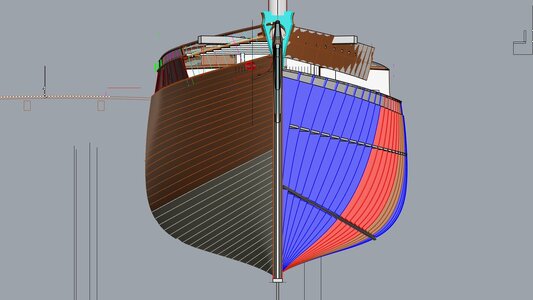
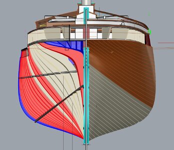
The two colours show the elm and teak planking and where it changed
We will never know I guess, and the sketch done of Cutty Sark while she was being built in Dumbarton does not show it as its too far away.


The two colours show the elm and teak planking and where it changed
Last edited:
A note about Teak decking and why I recommend Anigre for teak
Firstly its cheapish.
Secondly it is very fine grained so no big pores to deal with
Thirdly it has fine grain patterns if cut right looking like scale timber, and lots of subtle colour variation in a board.
here is a photo of my stash , note the colours compared to photos, its very close, the best I know of in my experience.
Even the greyer boards look like more weathered teak
These boards to the right are about 120mm wide
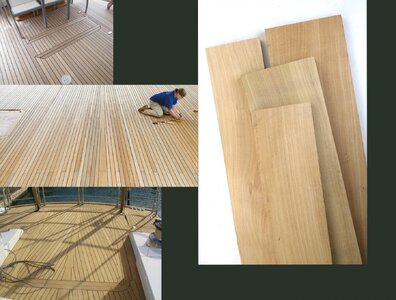
On another note if you go and buy Anigre make sure you don't get stuff with figure in it, it has a lot of fiddleback/flame figure great for using in furniture and guitars which I do use it for , like below, but it will look bad as model decking and is very hard to work.
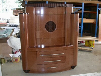
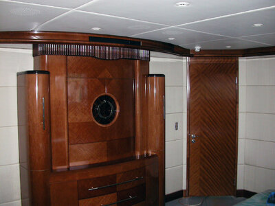
This image shows a cabinet that is veneered in Anigre and stained, note the striped figure in it common in most Anigre veneer, try to buy solid timber not veneer.
The Anigre is the lighter of the 3 woods over most of the cabinet, the others are Black walnut and Macassar Ebony.
And installed on a the Super Yacht, MY Silver Fox.
Better lighting making grain more prominent than the first photo.
Firstly its cheapish.
Secondly it is very fine grained so no big pores to deal with
Thirdly it has fine grain patterns if cut right looking like scale timber, and lots of subtle colour variation in a board.
here is a photo of my stash , note the colours compared to photos, its very close, the best I know of in my experience.
Even the greyer boards look like more weathered teak
These boards to the right are about 120mm wide

On another note if you go and buy Anigre make sure you don't get stuff with figure in it, it has a lot of fiddleback/flame figure great for using in furniture and guitars which I do use it for , like below, but it will look bad as model decking and is very hard to work.
This image shows a cabinet that is veneered in Anigre and stained, note the striped figure in it common in most Anigre veneer, try to buy solid timber not veneer.
The Anigre is the lighter of the 3 woods over most of the cabinet, the others are Black walnut and Macassar Ebony.

And installed on a the Super Yacht, MY Silver Fox.
Better lighting making grain more prominent than the first photo.

Last edited:
Rabbet carving on this model.
Richard, thanks for the great video. Nicely done! Magic Mike
Progress shots from this morning
Anigre deck planking stock ready to be sawn into planks.
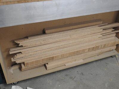
American Cherry ready to be sawn for hull planks.
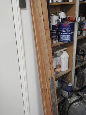
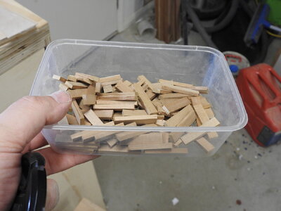
38mm prop sticks to hold down tween deck.
Foredeck laminating Jig, sorry second one is blurry
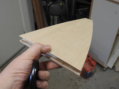
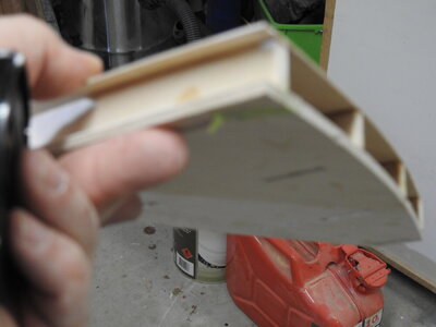
The glued .8mm deck base glued from 2 x.4mm 3 ply layers. This has the sheer and camber now formed into it and will hold it's shape without needed structural elements to hold its form, although the Samson posts and pillars will do so anyway, it can be framed up with styrene angle and sheet as per the ship under the deck
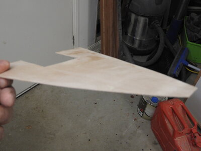
The cutwater parts being fine tuned for fit.
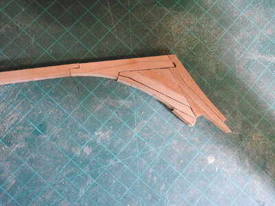
Final assembly of the hull, forward frames are in, tween decks loaded in and closing hull ready to glue down tween decks, note hatch coamings and longitudinals holding it all in line vertically.
Anigre deck planking stock ready to be sawn into planks.

American Cherry ready to be sawn for hull planks.

38mm prop sticks to hold down tween deck.

Foredeck laminating Jig, sorry second one is blurry


The glued .8mm deck base glued from 2 x.4mm 3 ply layers. This has the sheer and camber now formed into it and will hold it's shape without needed structural elements to hold its form, although the Samson posts and pillars will do so anyway, it can be framed up with styrene angle and sheet as per the ship under the deck

The cutwater parts being fine tuned for fit.

Final assembly of the hull, forward frames are in, tween decks loaded in and closing hull ready to glue down tween decks, note hatch coamings and longitudinals holding it all in line vertically.


Last edited:
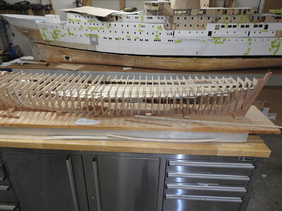
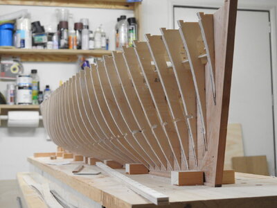
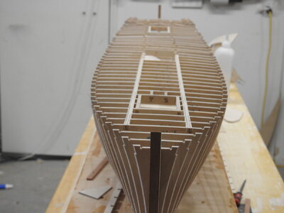
Frame for hull is complete and glued, just the tween decks to glue down next and then the decks, sheerplates and bilge stringers and it's planking time.
Note tween deck parts are already inside and can be moved around out of the way to glue.
I should add that even thought the deck will hold the ship in line I will be bracing the stem, stern post next and bracing 2-3 midship frames level just to keep it all lined up while decks are glued in.
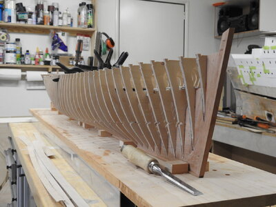
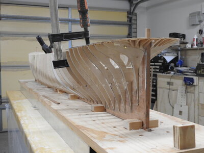
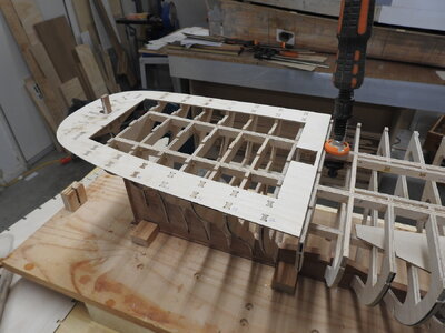
In this shot the theory behind the construction is seen, most models go with the knuckle or white moulding on the hull at deck level for ease of build, even Longridge did on his but it's not it's higher then the deck and that is why is this shot you can see how the deck level inside the saloon area is apparently lower, its the same height as deck but the plywood surround around the saloon is the correct height for the knuckle and start of bulwark so its lifted up.
I hope that makes sense....
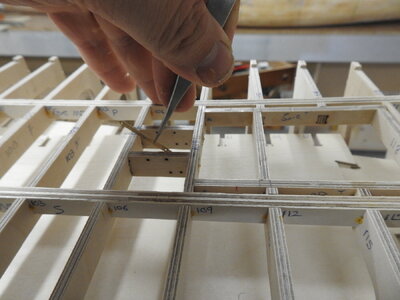
In the below image the brass fixing strap for the main stay connections to the deck are shown, they are pinned through to the carlings, the holes can be seen behind, these will get brass blackened and protrude through the deck. this should be good and strong
Here it is in cad, might be easier to explain
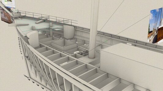
And in reality in foreground, remember the frames in the model correspond exactly with the beams in the ship
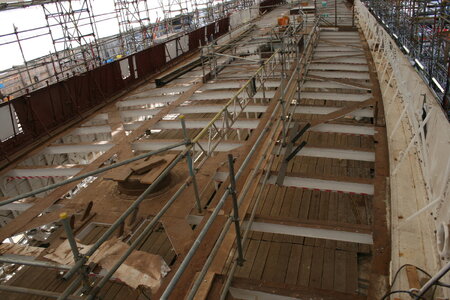
Views of deck
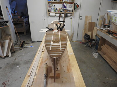
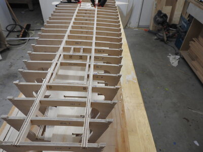
Using the poop frame to assemble the saloon in to hold its shape.
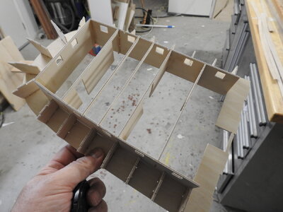
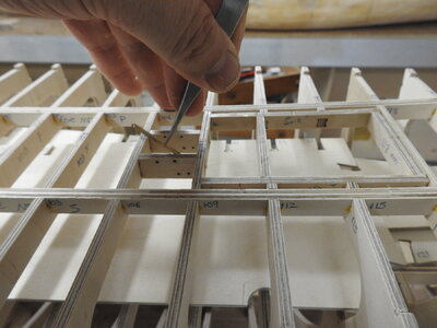
Note tween deck parts are already inside and can be moved around out of the way to glue.
I should add that even thought the deck will hold the ship in line I will be bracing the stem, stern post next and bracing 2-3 midship frames level just to keep it all lined up while decks are glued in.


In this shot the theory behind the construction is seen, most models go with the knuckle or white moulding on the hull at deck level for ease of build, even Longridge did on his but it's not it's higher then the deck and that is why is this shot you can see how the deck level inside the saloon area is apparently lower, its the same height as deck but the plywood surround around the saloon is the correct height for the knuckle and start of bulwark so its lifted up.
I hope that makes sense....
In the below image the brass fixing strap for the main stay connections to the deck are shown, they are pinned through to the carlings, the holes can be seen behind, these will get brass blackened and protrude through the deck. this should be good and strong

Here it is in cad, might be easier to explain

And in reality in foreground, remember the frames in the model correspond exactly with the beams in the ship

Views of deck


Using the poop frame to assemble the saloon in to hold its shape.


Last edited:
I am very interested in a set of plans.Thanks guys
You are correct in that assumption Jim, there is absolutely nothing that needs to be soldered to them and those that do need fixing have enough area to CA on.
The only small fitting which needs to carry load are the boomkins and those can be pinned through.
Looks like I will be experimenting with milling aluminium on the CNC soon.
On another note I am playing with the idea of publishing this as a set of plans and templates that can be replicated at various scales to meet increasing demand for smaller scales.
What I am proposing will cost a little more than regular set of plans for the simple fact it will not be done on paper, the reason is paper moves.
I hope you all know this but you should never print on paper.
Plans should always be printed on drafting film, it is stable, semi transparent and heavy gauge making it tough and ideal for cutting with a knife and running a pencil around it.
View attachment 417112 The other huge advantage some of you may not realise is the ink used on film is almost like a wax and if ironed face down will transfer on to the wood
It can be shipped anywhere regardless of climate and it will not move.
The bonus of this is I don't have to limit you to my choices of timber although I am adamant of this personally, Anigre for decking as it looks identical to aged teak and American Cherry stained with golden yellow stain to replicate the golden brown of varnished teak.
But ultimately its up to you. Can I have some thoughts on this.
an example of this would be the frames and keel, I would provide each frame as a normal profile with the bevel also marked on it so it can be glued onto the ply cut out and bevelled with a file.
This was done in the same way before I owned a CNC and with care note the quality of the fits.
View attachment 417113View attachment 417114
The keel would be the same with the addition of 1:1sections at every frame and waterline, of the rabbet on a separate sheet that can be cut up.
rather than the frame notches being marked on keel I would mark the location of one side of the frame, to allow for users to supply a different thickness of frame, something along that line of approach
The accuracy of the model will not be compromised in any way, it's still as close as a shrunken version of the full size thing but users will just have to be good at scroll sawing and cleaning up to the very fine lines which will be very fine lines indeed .13mm or finer.
I would not think that anything smaller than 1/64 could be built to the proper level of detail, things would have to be dropped or scaled up to make it possible. though.
I would include plans for everything on the hull and masting, including the decking and planking and optional cast resin fittings.
Or am I stupid doing this and better off just doing proper plans of the ship at every level and letting you build your own and come up with you own construction method.
Can I have some thoughts on this from everyone?
I am very interested in a set of plans!Thanks guys
You are correct in that assumption Jim, there is absolutely nothing that needs to be soldered to them and those that do need fixing have enough area to CA on.
The only small fitting which needs to carry load are the boomkins and those can be pinned through.
Looks like I will be experimenting with milling aluminium on the CNC soon.
On another note I am playing with the idea of publishing this as a set of plans and templates that can be replicated at various scales to meet increasing demand for smaller scales.
What I am proposing will cost a little more than regular set of plans for the simple fact it will not be done on paper, the reason is paper moves.
I hope you all know this but you should never print on paper.
Plans should always be printed on drafting film, it is stable, semi transparent and heavy gauge making it tough and ideal for cutting with a knife and running a pencil around it.
View attachment 417112 The other huge advantage some of you may not realise is the ink used on film is almost like a wax and if ironed face down will transfer on to the wood
It can be shipped anywhere regardless of climate and it will not move.
The bonus of this is I don't have to limit you to my choices of timber although I am adamant of this personally, Anigre for decking as it looks identical to aged teak and American Cherry stained with golden yellow stain to replicate the golden brown of varnished teak.
But ultimately its up to you. Can I have some thoughts on this.
an example of this would be the frames and keel, I would provide each frame as a normal profile with the bevel also marked on it so it can be glued onto the ply cut out and bevelled with a file.
This was done in the same way before I owned a CNC and with care note the quality of the fits.
View attachment 417113View attachment 417114
The keel would be the same with the addition of 1:1sections at every frame and waterline, of the rabbet on a separate sheet that can be cut up.
rather than the frame notches being marked on keel I would mark the location of one side of the frame, to allow for users to supply a different thickness of frame, something along that line of approach
The accuracy of the model will not be compromised in any way, it's still as close as a shrunken version of the full size thing but users will just have to be good at scroll sawing and cleaning up to the very fine lines which will be very fine lines indeed .13mm or finer.
I would not think that anything smaller than 1/64 could be built to the proper level of detail, things would have to be dropped or scaled up to make it possible. though.
I would include plans for everything on the hull and masting, including the decking and planking and optional cast resin fittings.
Or am I stupid doing this and better off just doing proper plans of the ship at every level and letting you build your own and come up with you own construction method.
Can I have some thoughts on this from everyone?
A set of plans for me too. At least to start off with when they're ready of course. Getting back to cutting the rabbet, hasn't any one made a tool for that by now? Looks like a tool on rollers like the chisel sharpening tool would be great for the straight parts along the bottom of the false keel. Also can the metal angel tool be bought someplace? I've only seen plastic ones that look rather flimsy. What I'm seeing here is the work of a perfectionist in that the hull looks just as good during construction as it looks when it's finished. Maybe even better. Absolute beauty all the way. I am sure that all your experience with water tank models and building to larger sizes has given you the knowledge and comfort for building in bigger size. But when you compare my Cutty Sark at 1:78 scale, it's considered a Large scale model in the hobby and still quite a bit smaller than what you are familiar with. I am so happy that you have become a member here as you're experience has raised the bar on this forum to unheard of heights. I'm very excited that now I can see what I'm up against with my plans for the Great Republic. Hope I live long enough to build it. Ha! Please don't dawdle because I'm already 82 next Tuesday. Oh yes, I like chocolate cake the best. Norgale
PS: I see that just about all your wood work, at least at this stage, is plywood. I'm curious as to what grade you use and what thickness is that which you use for the hull framing? It looks to be very strong and that's what I would go for.
PS: I see that just about all your wood work, at least at this stage, is plywood. I'm curious as to what grade you use and what thickness is that which you use for the hull framing? It looks to be very strong and that's what I would go for.
Last edited:


