Hello to all,
Well I have read everything I can on the gun configuration, stern configuration and hull configuration of the
Santisima Trinidad until I have a headache. So I am declaring this to be my stake in the ground.
THE GUNS
Unless there are some documents that have not been released in the last 244 years, this is pretty much the general opinion I have found from all the books, websites and data I have on the ship. Below is a matrix on the ordnance the
Santisima Trinidad had during various years.

The
Santisima Trinidad was certainly capable of carrying 144 weapons. Maybe not well but she could carry them. I use the term ‘weapons’ because depending on one’s passion for this ship, it seems to determine what they (the weapons) are called and defines how many of them there are. In some cases, the placement of the weapon determined if it would be counted or not. I think this is the reason for the variations in the counts from source to source.
The terms mortar and howitzer were used interchangeably in what I read. The esmeril was like a scatter gun on a pivot capable of firing single shots quickly or fire a spray of stone or iron balls across the deck of an opposing ship. There is still some dispute if the
Santisima Trinidad was fitted for 144, 140 or 136 weapons the day of her final battle.
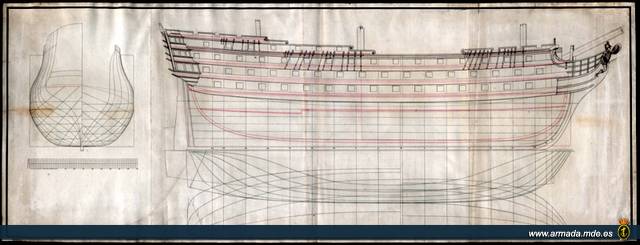
I found a discrepancy between the OcCre model and a drawing from the
Museo Naval de Madrid I have of the 1805 version of
Santisima Trinidad. The model has one gun too many on each side of the 1st battery. So I plan on blocking off the two forward guns; one on each side of the 1st battery. Below is another matrix I developed based on the gun placement on the ship during various years.

I have four drawings from the
Museo Naval de Madrid that show the supposed configuration of the
Santisima Trinidad for the years 1771, 1778, 1795 and 1805. All four of these drawings show the four stern guns. I only found a mention of them in the Battle of Cape St. Vincent in 1797. There are some models I have seen with two stern guns and some with four stern guns. For whatever reason, I believe she had four stern guns and so will my ST.
THE HULL
Another point is the coppering of the hull. I found she was coppered between 1781 and 1782 due to a naval requirement. She was coppered again in 1803. So I will copper the hull of my ST.
THE STERN
The stern configuration is hard to tell. I have only the four drawings from the
Museo Naval de Madrid that show the different stern configurations and a blog that said the correct configuration was the one in the OcCre kit. The 1805 configuration is devoid of any decorations other than the Spanish seal (I think that is what it is). Unless I am swayed differently by the time I get to that point, I think I am staying with the OcCre kit stern plus four guns.
THE COLOR
The last thing is the color of the gun ports. It is a no brainer that the ports were red with a black divider. The only vague part is the white stripe. Some show it with one. Others show it with two. Still others show it with no white stripe at all. The midshipman on the
HMS Neptune said it had one. I personally like the look of the two white stripes so I need to pounder this a bit more. The rest of her colors were pretty much standard for the Spanish Navy at that time.
Hope this has not bored anyone. I thought it would be some good information to share.
Later,
Don