Cad design drawing the steam frigate Mississippi

I kid you not it takes hundreds of research hours and hundreds of CAD time hours to complete a set of working modeling plans for a model as complex as the Mississippi. Because you just can not sit in front of a computer day in and day out the time is stretched into a year or more.

This is one reason you do not see many new kits out on the market or why you see the same subjects being done over and over it is the sheer amount of time it takes for the R&D work to come up with an original project. Even if your a wiz at CAD if you do not know what you are drawing and how a ship is built then knowing CAD is useless.

Then the problem of paying for the research material, finding someone who can understand the material and doing the drawings then break those down into cutting files will run into the thousands of dollars.
 
the stern of the Mississippi is nothing like the early flat type sterns we are all use to seeing. This stern is a round stern and built totally different. So rather than getting into construction details of a round stern I am doing an about face and go back to the midship and start drawing all the frames forward until I come to the bow frames. Another reason I am avoiding the stern right now is because I never built a round stern so I have to do some research and figure out how it is done.

so in another week I will post a progress report
 

Attachments

  • 20180724_073135[3320].jpg
    20180724_073135[3320].jpg
    177.9 KB · Views: 14
WOW!

there are 75 drawings of the Mississippi in the national archives some have gone missing and the archivist said that is because over time the missing drawings were miss filed and odds of finding them were zero

and you actually have one of them OMG Jerry I got to have a jpeg file of the plan I have been searching high and low and thought I would have to make up something for the 10 inch pivot gun on the bow.

I just cant believe a million to one shot in the dark that plan would come to light I jumped out of my chair doing the happy dance.
 
I have a higher res image if you need it :)

con20180628a.jpg
I had the same issue with Constellation, the original spar deck plans' missing which was a real pain.
Some were forgeries planted there by the a-holes in Baltimore trying to make her a frigate back in the 60's
 
Last edited:
references say there are 75 drawings for the Mississippi but when the hired researcher went to look many are either missing because they were put back in the wrong files or the drawing is to delicate to reproduce. so anyhow yes I would need a high res of the swivel gun.

progress report I have moved 10 more frames forward and still going on

50 frames done.JPG


looking at the bodyplan you can see on the left the blue half frames will rest against the deadwood where they all come together, on the right side at the bow you can see how the cant frames are getting higher up the stem.

blue cant frames.JPG
 
here is the gun deck drawing these drawings are 4 feet so they are in 2 sections

108-7-14S Gun Deck, 2of2.jpg


108-7-14S Gun Deck, 1of2.jpg
.
here is the spar deck

108-7-14R Spar Deck, 2of2.jpg

108-7-14R Spar deck, in two parts 1841, 1 of 2,.jpg
 
Last edited:
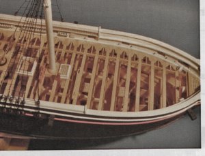
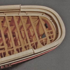
now that we are looking at the deck plans I am not sure what I am looking at pointed to by the black and gray arrows. My first thought was the bulkheads flare out or tumble inward but that does not seem right I do not see a flaring out on the bodyplan. Right now the double bow is a mystery

bow.jpg
 
Shortly searching on the photos available in internet of this ship.....it seems, that the lower part of the stern, is somehow cantilever (your mark black arrow) and the grey is the higher part of the bow.

I enlarged some photos and engravings

0986112011.jpg 0986112021.jpg 0986112031.jpg
 
looking at the spar deck plan it shows the gun ports darkened in and at the bow there is one long gun port which makes sense because that bow gun swivels. that long gun port is falling between the inside and outside drawings of the bulwarks.
 
The light gray arrow is the hull thickness, the dark gray arrow is the top of the bulwark. What's being referred to as the "gun deck" with the pivot gun, IS the spar deck. Below would be the birth deck. No stern pivot huh?
 
No stern pivot huh?

looking at the plan I would say gun ports wrap around the stern which makes more sense because with a pivot gun the entire stern section of the bulwarks would have to open up. Also with one pivot gun you would fire then stop and reload and fire again with 4 guns at the stern you can fire continually. Notice the deck structure is built much stronger at the stern my guess it to take the weight of 4 guns.
 
Last edited:
G'day Dave
I have read this log again. It's so informative and sometimes easy to read, but not too easy to digest for a person like me, CAD ignorant!
Dave, I don't know you doit mate to make all of these frames so quickly. How many hours have you done so far on the drawings?
Happymodeling
Greg
 
at the time of building the steam navy several ships were built 2 sloops of war the Susquehanna and the Powhatan were built right after the Mississippi.
the official records stated as commissioned the Susquehanna carried 3 10 inch pivot guns on circles fore and aft one stern and 2 on the forecastle.

sus stern.JPG


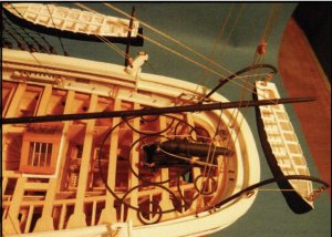
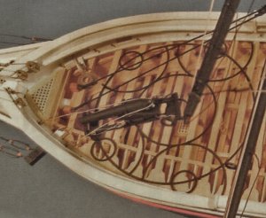
this model shows only one pivot gun at the bow so I can not say if the configuration of the iron circles would be the same for one gun as for two guns.

sus1.jpg

notice in the above photo and the two below the double bulwark set up this might be the reason for the drawing in the last post with the 2 arrows pointing to a double bulwark. The Mississippi did not have a pivot at the stern so the stern is not drawn like the bow bulwarks.

I am going to venture a guess and say the steam frigates did not have pivots for and aft but the sloops of war did.

sus2.jpg
sus3.jpg
 
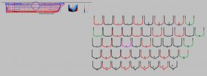
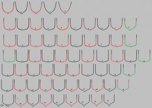
WHAM! BAM! ok all the frames are drawn from stem to stern except for the 1/2 cant frames at the bow and the stern those I will do a different way.

all frames.JPG


G'day Dave
I have read this log again. It's so informative and sometimes easy to read, but not too easy to digest for a person like me, CAD ignorant!
Dave, I don't know you doit mate to make all of these frames so quickly. How many hours have you done so far on the drawings?
Happymodeling

Greg

I can't give you a time because CAD does not keep time on the drawing only how long the file is open. What I do when I am working on a drawing is to keep the cad file open when I finish I just put the computer in sleep mode. I work on a file in short work sessions. Like when I am making dinner and waiting for something to cook I will sit down and draw a frame or two and I do this all day. So far the Mississippi file started May 22 and I finished the frames today that is a total time of 40 days 8 hours and 31 minutes. The actual time I spent drawing is about 22 hours.


The Mississippi frames were easy to draw because they are straight sides and bottom the only real curves involved is at the turn of the bilge.
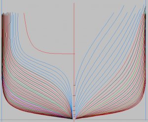
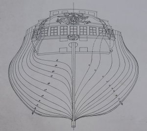
Now take a hull like this one with all the complex curves this would take me twice as long if not longer.
I have been using CAD for over 30 years so I know the program up down and sideways and a lot of quick tricks which helps with speed.

curved hull lines.jpg
 
Back
Top