First Thread? Making a Mini CNC Milling Machine

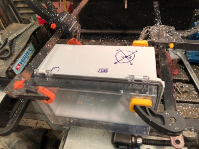
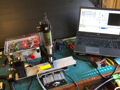
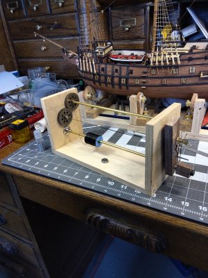
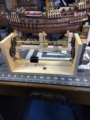
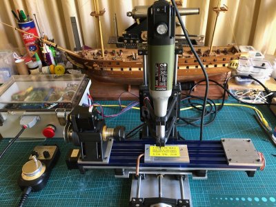
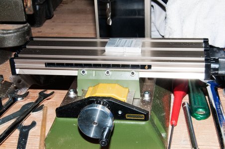
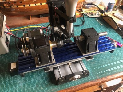
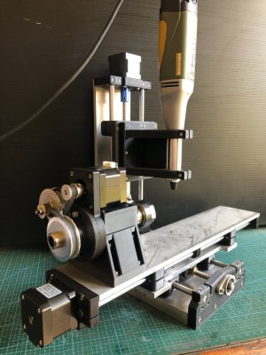
Another update on the mini CNC mill build. The mill itself is made, assembled, and ready to run (photo 1). But I have been waiting, not very patiently, for parts to arrive from USA and China. The hardened steel rods which I was sent originally, were 0.03mm undersized (just over 1 thou for readers who prefer imperial, cubits or acorns), so another batch is due to arrive soon.
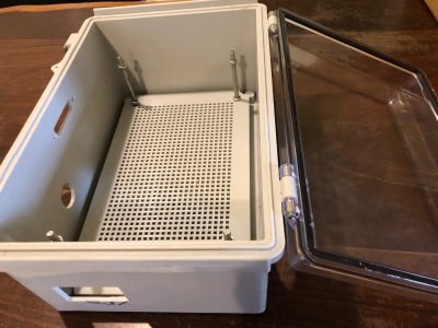
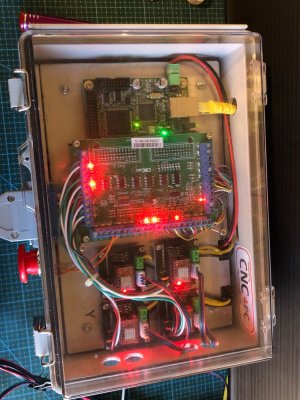
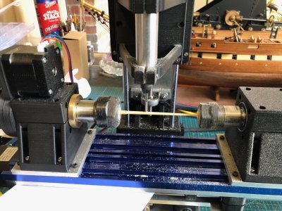
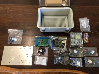
Meanwhile, most of the electronic bits arrived, so I have made a start on the control box. The electronic components (photo 2) consist of the box with a lockable transparent lid, a power switch, power transformer, E stop switch, multiple wires not shown, 4 stepper motor drivers, CNC controller board, breakout board, and probably more that I will remember during assembly.
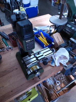
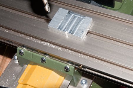
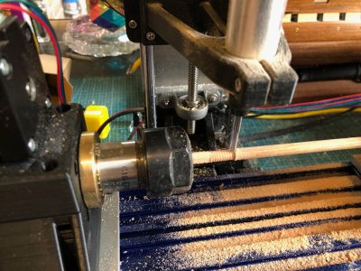
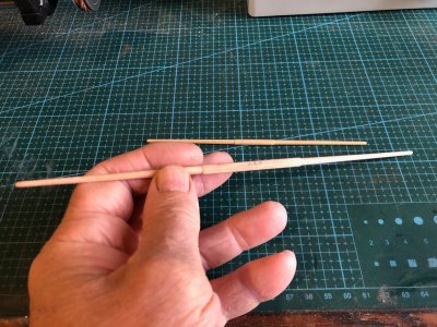
The next photos are various stages to date of assembling the control box. I marked approximately where the various penetrations needed to be cut, then cramped the plastic box to a large angle plate, and milled the penetration shapes with my big CNC mill, on 3 faces of the box. Fortunately for me, the designer of the machine, Stuart Tankard, had done the exacting work of designing and locating the various shaped penetrations.
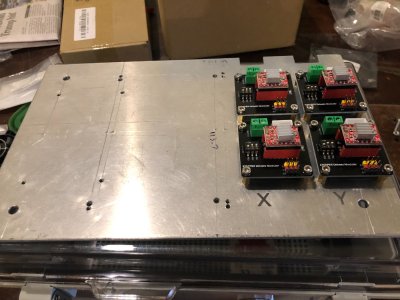
There are 3 layers of components. The power transformer occupies the lowest, then the aluminium plate sits on the large standoff bolts, then there are 2 layers of electronic PCB's on the alu plate.
Hopefully I will have this all working in another 2 or 3 workshop sessions.
IMG_5278.JPG

IMG_5269.JPG

IMG_5274.JPG

IMG_5275.JPG

IMG_5276.JPG
 
Coming along nicely John. I will be eager to see the finished product.
Will you be able to supply a BOM with links to your suppliers for those of us that would like to emulate your skills, and attempt a similar build?
 
Chestcutter, I will finish it, test it, then publish the BOM, and make some arrangement for sharing the plans and necessary files. It has required expertise in 3D printing, cutting, drilling and tapping aluminium, and some metal lathework. But anyone who can make a scale model period ship would be mentally equipped to take on a few extra skills?
 
Still waiting for the breakout board to arrive from USA. I do hope that it was sent by air. When it arrives I will start wiring all of the components, with some expert help from Stuart. I will keep a record of the wiring as much as possible.
Meanwhile I have been thinking about using the CNC controls to run a CNC seizing/serving machine. I was planning a stand alone seizing/serving machine, just moving the CNC controls from the mini mill to seizing/serving machine as required. But now I am considering just adding some accessories to the mini mill to do the job. The only restriction will be that the maximum length of rope that will be able to be continuously served will be 150mm. To serve longer lengths would require serving 150mm then repositioning the rope in the machine headstock and tailstock and doing a further 150mm. That might be do-able. Hmm. Has anyone else tried this? What would be the maximum length of model rope to be served on, say a 1:72 Victory, for example? Just considering.
Also considering using the CNC to do worming. That would require 3 or 4 feed spools of worming thread, to worm all of the rope grooves simultaneously, or 3 or 4 runs of a single feeder. On reflection, I will probably stick to a single thread worming feeder. I could see an unholy mess if it gets too complicated.
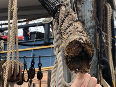
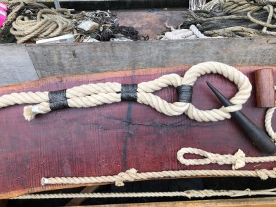
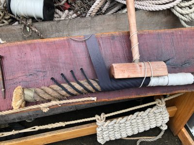
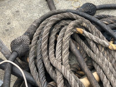
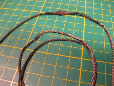
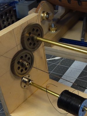
The photos are nice examples of worming, seizing, serving and wrapping which I noted at a recent visit to the HMB Endeavour replica at the National Maritime Museum, Sydney. This full size replica is claimed to be the most accurately made replica in existence. I took quite a few other pics of the ship if there is any interest? The first shot, of the 4 worming threads being demonstrated, is what stimulate my thoughts of using up to 4 bobbins on my proposed machine.IMG_5138.JPGIMG_5133.JPG IMG_5134.JPGIMG_5138.JPGIMG_5140.JPGIMG_5133.JPG
 
Difficult your plan to serve 150 mm. And then replacement the rope to do anotger 150 mm. That will be a pain in the ass. Believe me, I already did a lot of seizing and rope making. It's possible ofcourse. But serve a rope of 400 mm. Means 3 times replacement of the rope. You will gonna hate serving rope.
Better to build a machine where you can go to 80 cm or more. I build one and I can make all kind of rope in it.
IMG_4540.JPG

I'm building a serving tool in AutoCAD to print it on a 3D printer. It will look like the RC model. When I finished it, I will share it here. But that takes time to design and make it.
 
Still waiting for the breakout board to arrive from USA. I do hope that it was sent by air. When it arrives I will start wiring all of the components, with some expert help from Stuart. I will keep a record of the wiring as much as possible.
Meanwhile I have been thinking about using the CNC controls to run a CNC seizing/serving machine. I was planning a stand alone seizing/serving machine, just moving the CNC controls from the mini mill to seizing/serving machine as required. But now I am considering just adding some accessories to the mini mill to do the job. The only restriction will be that the maximum length of rope that will be able to be continuously served will be 150mm. To serve longer lengths would require serving 150mm then repositioning the rope in the machine headstock and tailstock and doing a further 150mm. That might be do-able. Hmm. Has anyone else tried this? What would be the maximum length of model rope to be served on, say a 1:72 Victory, for example? Just considering.
Also considering using the CNC to do worming. That would require 3 or 4 feed spools of worming thread, to worm all of the rope grooves simultaneously, or 3 or 4 runs of a single feeder. On reflection, I will probably stick to a single thread worming feeder. I could see an unholy mess if it gets too complicated.
The photos are nice examples of worming, seizing, serving and wrapping which I noted at a recent visit to the HMB Endeavour replica at the National Maritime Museum, Sydney. This full size replica is claimed to be the most accurately made replica in existence. I took quite a few other pics of the ship if there is any interest? The first shot, of the 4 worming threads being demonstrated, is what stimulate my thoughts of using up to 4 bobbins on my proposed machine.View attachment 484610View attachment 484612 View attachment 484609View attachment 484610View attachment 484611View attachment 484612
Brilliant photos of the ropes and the mouse. Is this from Sydney maritime museum?
Thanks for sharing John.
 
Difficult your plan to serve 150 mm. And then replacement the rope to do anotger 150 mm. That will be a pain in the ass. Believe me, I already did a lot of seizing and rope making. It's possible ofcourse. But serve a rope of 400 mm. Means 3 times replacement of the rope. You will gonna hate serving rope.
Better to build a machine where you can go to 80 cm or more. I build one and I can make all kind of rope in it.
View attachment 484615

I'm building a serving tool in AutoCAD to print it on a 3D printer. It will look like the RC model. When I finished it, I will share it here. But that takes time to design and make it.
Thanks for the advice, which makes sense, and comes from one who is obviously experienced. I would like to see some photos of your serving machine, if possible. The ropes in your photo are the sort of standard which I am aiming for.
 
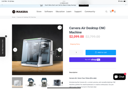
A company called Makera released this machine for sale today. It’s a desktop CNC Mill and can also get a fourth axis and laser attachments.

Selling for $2100 USD

IMG_0659.png

Would be interested to see how it compares to other machines discussed here.
 
Back
Top