First Thread? Making a Mini CNC Milling Machine

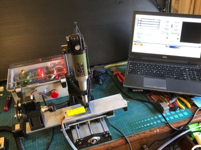
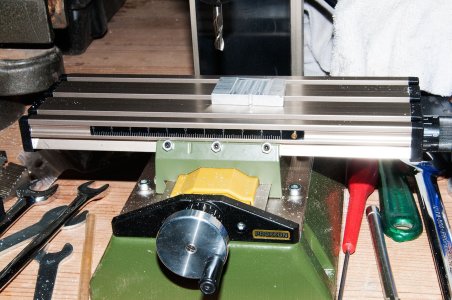
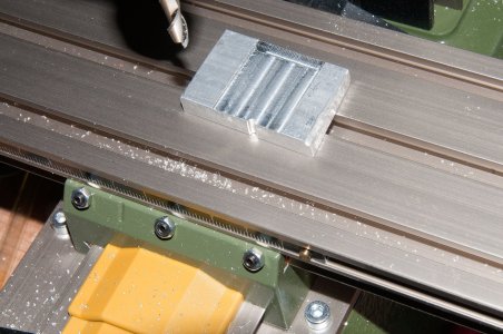
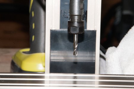
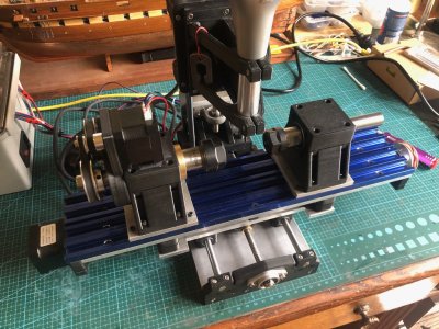
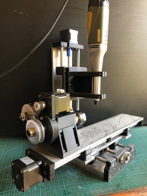
Another update on the mini CNC mill build. The mill itself is made, assembled, and ready to run (photo 1). But I have been waiting, not very patiently, for parts to arrive from USA and China. The hardened steel rods which I was sent originally, were 0.03mm undersized (just over 1 thou for readers who prefer imperial, cubits or acorns), so another batch is due to arrive soon.
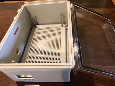
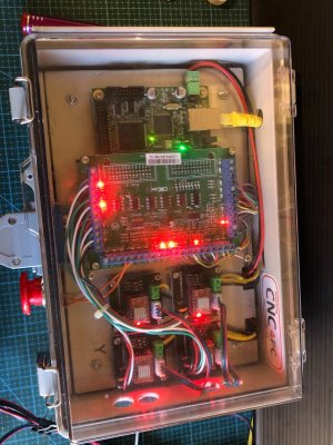
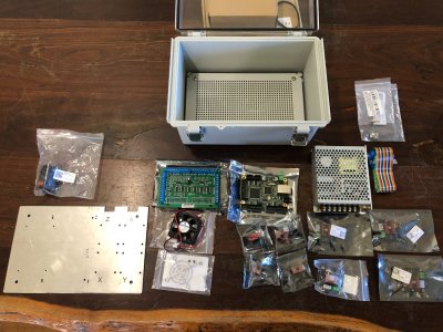
Meanwhile, most of the electronic bits arrived, so I have made a start on the control box. The electronic components (photo 2) consist of the box with a lockable transparent lid, a power switch, power transformer, E stop switch, multiple wires not shown, 4 stepper motor drivers, CNC controller board, breakout board, and probably more that I will remember during assembly.
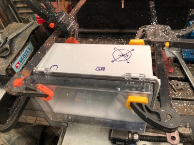
The next photos are various stages to date of assembling the control box. I marked approximately where the various penetrations needed to be cut, then cramped the plastic box to a large angle plate, and milled the penetration shapes with my big CNC mill, on 3 faces of the box. Fortunately for me, the designer of the machine, Stuart Tankard, had done the exacting work of designing and locating the various shaped penetrations.
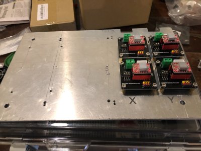
There are 3 layers of components. The power transformer occupies the lowest, then the aluminium plate sits on the large standoff bolts, then there are 2 layers of electronic PCB's on the alu plate.
Hopefully I will have this all working in another 2 or 3 workshop sessions.
IMG_5278.JPG

IMG_5269.JPG

IMG_5274.JPG

IMG_5275.JPG

IMG_5276.JPG
 
Coming along nicely John. I will be eager to see the finished product.
Will you be able to supply a BOM with links to your suppliers for those of us that would like to emulate your skills, and attempt a similar build?
 
Chestcutter, I will finish it, test it, then publish the BOM, and make some arrangement for sharing the plans and necessary files. It has required expertise in 3D printing, cutting, drilling and tapping aluminium, and some metal lathework. But anyone who can make a scale model period ship would be mentally equipped to take on a few extra skills?
 
Still waiting for the breakout board to arrive from USA. I do hope that it was sent by air. When it arrives I will start wiring all of the components, with some expert help from Stuart. I will keep a record of the wiring as much as possible.
Meanwhile I have been thinking about using the CNC controls to run a CNC seizing/serving machine. I was planning a stand alone seizing/serving machine, just moving the CNC controls from the mini mill to seizing/serving machine as required. But now I am considering just adding some accessories to the mini mill to do the job. The only restriction will be that the maximum length of rope that will be able to be continuously served will be 150mm. To serve longer lengths would require serving 150mm then repositioning the rope in the machine headstock and tailstock and doing a further 150mm. That might be do-able. Hmm. Has anyone else tried this? What would be the maximum length of model rope to be served on, say a 1:72 Victory, for example? Just considering.
Also considering using the CNC to do worming. That would require 3 or 4 feed spools of worming thread, to worm all of the rope grooves simultaneously, or 3 or 4 runs of a single feeder. On reflection, I will probably stick to a single thread worming feeder. I could see an unholy mess if it gets too complicated.
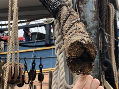
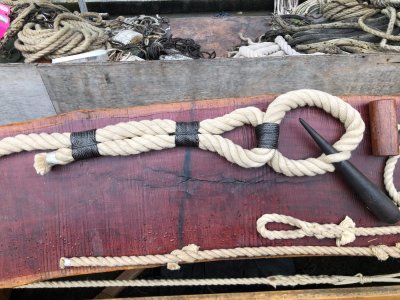
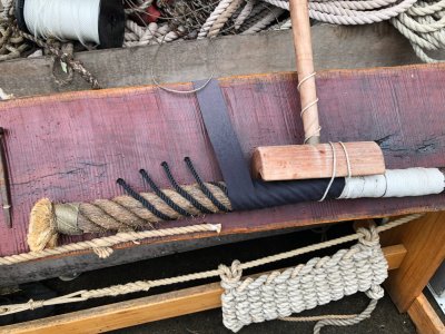
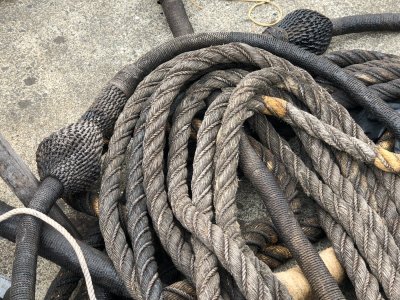
The photos are nice examples of worming, seizing, serving and wrapping which I noted at a recent visit to the HMB Endeavour replica at the National Maritime Museum, Sydney. This full size replica is claimed to be the most accurately made replica in existence. I took quite a few other pics of the ship if there is any interest? The first shot, of the 4 worming threads being demonstrated, is what stimulate my thoughts of using up to 4 bobbins on my proposed machine.IMG_5138.JPGIMG_5133.JPG IMG_5134.JPGIMG_5138.JPGIMG_5140.JPGIMG_5133.JPG
 
Difficult your plan to serve 150 mm. And then replacement the rope to do anotger 150 mm. That will be a pain in the ass. Believe me, I already did a lot of seizing and rope making. It's possible ofcourse. But serve a rope of 400 mm. Means 3 times replacement of the rope. You will gonna hate serving rope.
Better to build a machine where you can go to 80 cm or more. I build one and I can make all kind of rope in it.
IMG_4540.JPG

I'm building a serving tool in AutoCAD to print it on a 3D printer. It will look like the RC model. When I finished it, I will share it here. But that takes time to design and make it.
 
Still waiting for the breakout board to arrive from USA. I do hope that it was sent by air. When it arrives I will start wiring all of the components, with some expert help from Stuart. I will keep a record of the wiring as much as possible.
Meanwhile I have been thinking about using the CNC controls to run a CNC seizing/serving machine. I was planning a stand alone seizing/serving machine, just moving the CNC controls from the mini mill to seizing/serving machine as required. But now I am considering just adding some accessories to the mini mill to do the job. The only restriction will be that the maximum length of rope that will be able to be continuously served will be 150mm. To serve longer lengths would require serving 150mm then repositioning the rope in the machine headstock and tailstock and doing a further 150mm. That might be do-able. Hmm. Has anyone else tried this? What would be the maximum length of model rope to be served on, say a 1:72 Victory, for example? Just considering.
Also considering using the CNC to do worming. That would require 3 or 4 feed spools of worming thread, to worm all of the rope grooves simultaneously, or 3 or 4 runs of a single feeder. On reflection, I will probably stick to a single thread worming feeder. I could see an unholy mess if it gets too complicated.
The photos are nice examples of worming, seizing, serving and wrapping which I noted at a recent visit to the HMB Endeavour replica at the National Maritime Museum, Sydney. This full size replica is claimed to be the most accurately made replica in existence. I took quite a few other pics of the ship if there is any interest? The first shot, of the 4 worming threads being demonstrated, is what stimulate my thoughts of using up to 4 bobbins on my proposed machine.View attachment 484610View attachment 484612 View attachment 484609View attachment 484610View attachment 484611View attachment 484612
Brilliant photos of the ropes and the mouse. Is this from Sydney maritime museum?
Thanks for sharing John.
 
Difficult your plan to serve 150 mm. And then replacement the rope to do anotger 150 mm. That will be a pain in the ass. Believe me, I already did a lot of seizing and rope making. It's possible ofcourse. But serve a rope of 400 mm. Means 3 times replacement of the rope. You will gonna hate serving rope.
Better to build a machine where you can go to 80 cm or more. I build one and I can make all kind of rope in it.
View attachment 484615

I'm building a serving tool in AutoCAD to print it on a 3D printer. It will look like the RC model. When I finished it, I will share it here. But that takes time to design and make it.
Thanks for the advice, which makes sense, and comes from one who is obviously experienced. I would like to see some photos of your serving machine, if possible. The ropes in your photo are the sort of standard which I am aiming for.
 
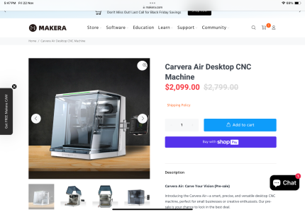
A company called Makera released this machine for sale today. It’s a desktop CNC Mill and can also get a fourth axis and laser attachments.

Selling for $2100 USD

IMG_0659.png

Would be interested to see how it compares to other machines discussed here.
 
Yep. That's what's coming. The future of making stuff. And just to think... My little CNC mill started as a method of accurately drilling belaying pin holes.
 
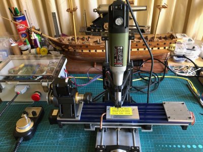
I have finished the Mini CNC Mill. Had to sort a few problems. First there was excessive play between the hardened steel 8mm rods and the linear bearings. I had measured the rods at 7.97mm diameter, so placed another order, and eventually received some slightly better rods, at 7.985, but no improvement in the play, so placed yet another order, (different supplier each time), and the final ones were 7.99, and still the play was excessive. Then the penny dropped, and I got some new linear bearings, which solved the play problem.
Next issue was excessive backlash in the acme screw nuts, but that was solved by installing them correctly, after some advice from my engineer friend. But it did involve a complete tear down of the machine several times before I did it properly.
Finally I installed all of the boards, switches, power supply, fuse, in the electronics control box. That was fairly straight forward, but I knew that I was not capable of doing the wiring, and booked my friend Stuart to do the job for me. Despite the fact that he has done the same installation on at least 4 occasions, it took him about 4 hours. I was taking frequent photos and making copious notes, so I could post that information here, but frankly, despite having a reasonable understanding of the principles of the workings, when issues arose on first testing, I had no idea how to do the trouble shooting, or how to fix the diagnosed problems.
So I am not going post the details of the electronics wiring. But I will post photos of the completed job. (see below).
If anyone does decide to go down a similar path, and is not an electronics expert, my strong advice is to have an expert do that part of the job. It is not for amateurs. The making of the mill, and the electronics component was simple compared to the wiring.
The mill is accurate and adequately rigid for 3d machining of plastic, wood, aluminium and brass parts, using cutters up tp to 3mm diameter.
The final cost of the mill and the electronics control box and manual handpiece, excluding repeat purchases due to quality of some components, was approx $AUD1000. That does not include Mach3 and Vectric V Carve Pro which I had purchased several years ago.
When I make some model ship building components I will post some videos and pics.
The most expensive component was the electronics box of controls (ESS board, breakout board, stepper motor control modules, switches etc) which was about 2/3 of the total. But with all of those red and green LED's it is quite a nice display!
Although "finished", I am planning to add a sacrificial wooden work surface, and a tailstock for the 4th axis rotary table. I think the tailstock will be useful for making spars.
And, I will be able to use the electronics box to run the CNC serving machine which is well underway. Again, waiting for components, this time from China.

IMG_5417.JPGIMG_5414.JPG
 
Difficult your plan to serve 150 mm. And then replacement the rope to do anotger 150 mm. That will be a pain in the ass. Believe me, I already did a lot of seizing and rope making. It's possible ofcourse. But serve a rope of 400 mm. Means 3 times replacement of the rope. You will gonna hate serving rope.
Better to build a machine where you can go to 80 cm or more. I build one and I can make all kind of rope in it.
View attachment 484615

I'm building a serving tool in AutoCAD to print it on a 3D printer. It will look like the RC model. When I finished it, I will share it here. But that takes time to design and make it.
Re the serving/seizing machine....thankyou for your response and advice, which I have followed. I am close to finishing my CNC controlled serving machine; just waiting for some timing gears to design and make the headstock and tailstock. I used 1000mm long rails and ball screw as the basis for the machine, which gives a working length of 800-850mm. I have made the bobbin carrier and will post details and pictures of the entire machine when it is finished. Your advice was appreciated.
 
Difficult your plan to serve 150 mm. And then replacement the rope to do anotger 150 mm. That will be a pain in the ass. Believe me, I already did a lot of seizing and rope making. It's possible ofcourse. But serve a rope of 400 mm. Means 3 times replacement of the rope. You will gonna hate serving rope.
Better to build a machine where you can go to 80 cm or more. I build one and I can make all kind of rope in it.
View attachment 484615

I'm building a serving tool in AutoCAD to print it on a 3D printer. It will look like the RC model. When I finished it, I will share it here. But that takes time to design and make it.
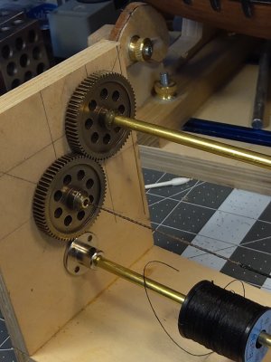
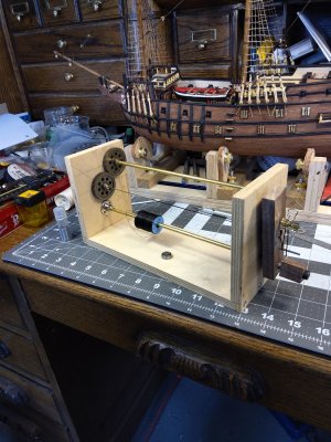
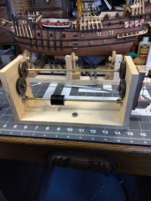
I'm interested in your design. I built a serving jig with metal gears, bearings, brass tubing and plywood frame but it is not 400mm.....wondering what you intend to 3D print....20210830_150422.jpg20210830_150322.jpg20210830_150313.jpg
 
Philski, there are 2 machines.
1. The 4 axis CNC mini mill with the electronics control box, will be used at home for making small 2D, 3D, or 4D parts in wood, plastic, and soft metals. It has workpiece capacity of 96 x 156 x 120 mm. As I am currently making a Mamoli Constitution I can see it being used to make spars with hexagonal or octagonal middle sections and tapers. And if required, making deadeyes. And any other small objects which I am able to draw.
2. The CNC serving seizing machine which will also use the electronics control box which was made for the mill. The machine construction is designed and currently under construction, waiting for parts to arrive from China. It has a working capacity up to 850mm. I will show pictures when it is finished and tested. Being CNC controlled, it will have the ability to vary the pitch of laying the serving thread. I imagine that will involve a learning curve.
 
Some extras for the mini mill...
The blue T slots will improve the ability for work holding. They can be quickly removed and reinstalled as necessary.
The alu plates will hold the rotary 4th axis, and its tailstock when I get around to making it.
I am also intending to make some sacrificial wooden work surfaces.
The alu plate in the centre of the work surface is a vacuum plate for holding plastic rectangles for making name badges and labels, an example which is shown, as made by the mini mill.
and my USS Constitution model (unfinished) on the work desk.T slots.JPG
 
20230125_121526.jpgNuestra_644.jpgPhilski, there are 2 machines.
1. The 4 axis CNC mini mill with the electronics control box, will beNuestra_645.jpgNuestra_640.jpg used at home for making small 2D, 3D, or 4D parts in wood, plastic, and soft metals. It has workpiece capacity of 96 x 156 x 120 mm. As I am currently making a Mamoli Constitution I can see it being used to make spars with hexagonal or octagonal middle sections and tapers. And if required, making deadeyes. And any other small objects which I am able to draw.
2. The CNC serving seizing machine which will also use the electronics control box which was made for the mill. The machine construction is designed and currently under construction, waiting for parts to arrive from China. It has a working capacity up to 850mm. I will show pictures when it is finished and tested. Being CNC controlled, it will have the ability to vary the pitch of laying the serving thread. I imagine that will involve a learning curve.
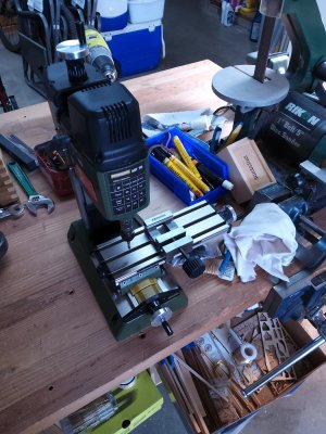
I used to use a Bridgeport for fun stuff ( and a Hardinge lathe) but that was when I had access to our machine shop at work (Hewlett Packard). Now, I only have a mini mill at home but for model making its perfect....
 
Last edited:
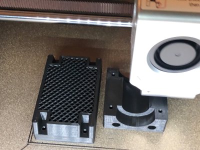
I printed the tailstock components yesterday, and assembled it .
The photo shows the printing about 50% completed, on the "strong" slicing setting. That involves 20% infill, and at least 6 print runs on the perimeters. The parts are impressively strong and accurate, straight off the Qidi printer. The second shot is the tailstock assembled and installed on the mill, ready for action.
If it all works as intended I should have some ship model parts to display soon. First job will be spars, with the tapering and central hexagonal sections made on the mini mill.
printing tailstock.jpgTailstock installed.JPG
 
Last edited:
TURNING SPARS WITH HEXAGONAL (or any number of facets) CENTERS ON THE MINI MILL
The mini mill can be used as a 3 axis mill to make 3d parts, but the 4th axis with tailstock also enables it to act as a small lathe.
The 4th axis, as set up, cannot rotate much faster than about 60rpm, and the rotating motor is not particularly powerful so it requires the Proxxon spindle with a small (3.125mm) sharp cutter, running at about 10-15,000 rpm to actually remove material.
The first use for which I have used it is to make the spars for the Mamoli Constitution.
The model spars are 3-6mm diameter, and up to 300mm long. the larger ones have a larger diameter central section which is hexagonal in section. The Mamoli plans specify that 1mm strips of wood are glued around the middle section, but I believe that in the ship these were often solid, part of the same logs as the rest of the spar.
So I decided to use the mini mill to make my spars from solid material, including the central hex section.
Some time was spent becoming familiar with the commands to run the mini mill as a "lathe", but eventually I worked it out.
The dowel was cut to about 20mm longer than the finished spar, so 8-10mm could be held in the collet chucks in the headstock and tailstock. The center of the spar was marked, and protruded about 10mm beyond the headstock chuck.
Then the end taper was cut using G code commands.
The spar was then turned around., again held in the center section, and the other end taper was cut.
Because I was using a 3.125mm cutter with a 0 degree cutting angle a shallow spiral mark was left on the surface of the tapered spar, but that was quickly sanded away after the milling was completed.

The next spar was longer (262mm) and had the hex section in the middle. Since ER collets will happily hold hexagon or any other geometric shape, I elected to make the hexagon cuts first, and cut the end tapers last.
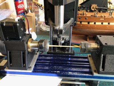
photo 1 shows a 4mm dowel held in the ER collets, and cutting an end taper using a 3mm cutter in the Proxxon spindle.
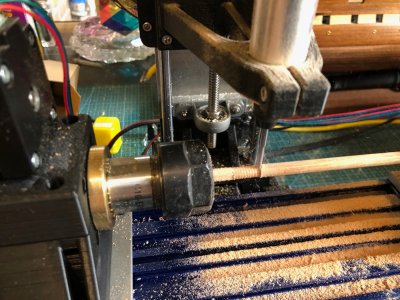
photo 2 is the larger spar with the hex section already cut and held in the headstock collet, and cutting a tapered end. The spiral shallow groove is clearly seen. That would not be seen with a more suitable cutter eg a ball nose.
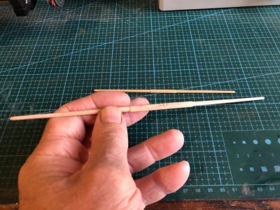
photo 3 is the first 2 spars made and sanded, ready for fittings to be attached.
IMG_5483.JPGIMG_5486.JPG

IMG_5488.jpg
 
Back
Top