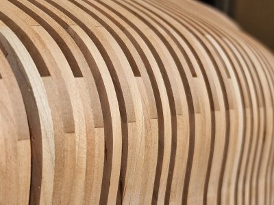
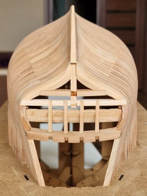
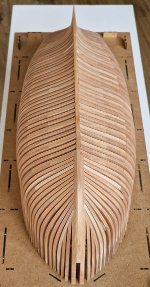
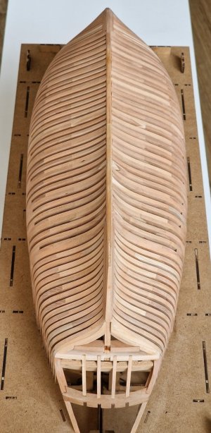
Definitely a translation issue herehave questions about multiple wedges in the casing
 |
As a way to introduce our brass coins to the community, we will raffle off a free coin during the month of August. Follow link ABOVE for instructions for entering. |
 |
 |
The beloved Ships in Scale Magazine is back and charting a new course for 2026! Discover new skills, new techniques, and new inspirations in every issue. NOTE THAT OUR FIRST ISSUE WILL BE JAN/FEB 2026 |
 |
Definitely a translation issue herehave questions about multiple wedges in the casing


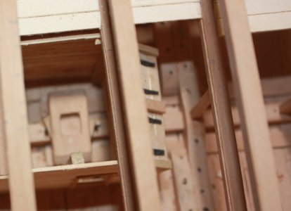
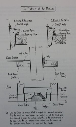
No, no. I know what you're talking about. I mean what's in the photo below. There is no illustration of this particular unit. That there were how many wedge-shaped boards in the sheathing.Definitely a translation issue hereAre you speaking of the pins and wedges on each side of the main mast step or the wedges between the masts and partners and filling chocks? If the former, from Steel: to have set of bolt holes bored into the kelson about 9 inches from the step. One forward and one aft, that the stp may be wedged to the rake of the mast at pleasure. The bolts about 1 3/8" diameter. (see left side of photo below)
View attachment 521799
View attachment 521801


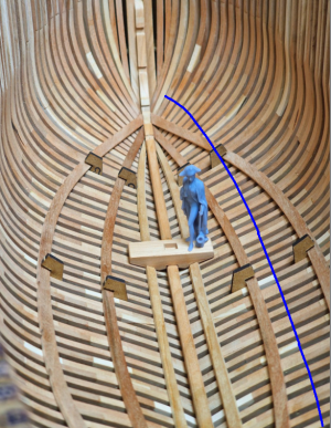
Wow, the world is small. Well, regarding the curvature of the boards, we must not forget that the keel is at an angle relative to the waterline and the deck too. Therefore, the curvature of the boards that is now on the hull completely repeats the level of the lower deck... So maybe it was like that. But it doesn't matter anymore, it is as it is. Thank youLike the external hull planking I don't think there were ever any wedge shaped pieces in the internal planking. Antscherl shows stealers on the Swan class sloops and the drawings I posted above show that stealers and drop strakes both were used. I just found in Peter Goodwin's The Construction and Fitting of the English Man of War, regarding the internal planking ---> Towards the forward and after ends of the hold the lay of the planks was made to diminish in width so that they could be worked to the curvature formed by the rise of the floors.
If you can see the joints of the floors to the futtocks on the model, this will give a good indication at least at two lines of curvature for the planking, the floors and 1st futtock and alternating floors and 2nd futtocks.
Hope this makes some sense. If my grandfather (from Lviv) who was a wood worker all his life was still around I would ask them to help me describe it in Ukrainian and then we'd have some fun
Allan
View attachment 521807
View attachment 521808

Hi, I ask, ( I don't remember if I asked already)shouldn't the pieces be nailed down? FrankThe second pair of boards already exists, now we will glue the first pair (those closer to the keel, Limber strike).
And to position the boards in the exact place, I used the stationery clips, plus wood (b - in the photo below). Which corresponds to the distance from the keel to the boards on the Mast step (a - in the photo). By the way, on the Mast step there is a ledge (with - in the photo) that needs to be combined with a chute on the keelson.
View attachment 521655
And now, you can glue the boards and just rest against the clips, and they will be glued evenly.
View attachment 521656
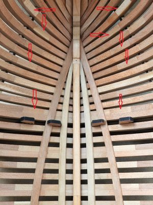
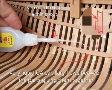
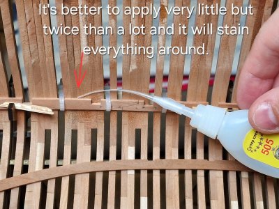
By the way, the gluing technique is the same. I dot the TiteBond II glue on each frame, except for the most lateral ones. I apply CA gel on the bottom. My wife helps me. While I hold the CA point - it holds the board over the PVA. And as soon as the CA sticks, I hold the place where the PVA was for another 5 minutes and everything is ready. Fixation without devices takes 6-7 minutes and you can work further.
View attachment 521657
And here is the finished symmetrical result.
View attachment 521658
View attachment 521659
View attachment 521660
And after that I glued the Mast step.
View attachment 521661
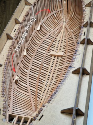
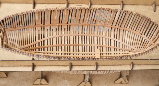
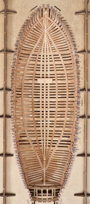
Next in line is the third pair of powerboards. Anatomically, this is most likely Upper strike of thickstuff footwaling, but the thickness and width of the board from the set are combinations of the aforementioned and Thickstuff over first futtock heads. (whatever that means)))
It is better to adjust them also from the front.
View attachment 521663
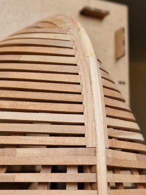
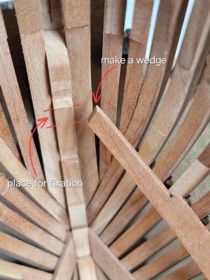
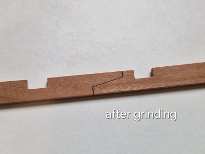
We still remember that the board is spinning in a spiral and you need to make a bevel in order to press it like this without a gap. And the joint hit as in the photo.
View attachment 521664
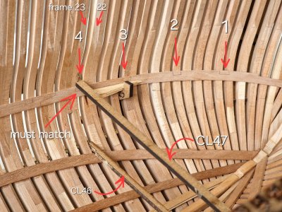
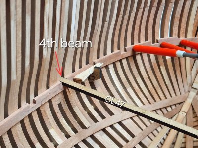
But you need to take into account a very vague moment. The ket includes a positioner (part CL 46).
It is necessary that this part passes between the 22th and 23th frames and gets into the groove for the 3rd beam of the lower holly. That is, you need to adjust the board in front so that this happens!
View attachment 521665
Well, at the back, similarly, we also cut off until we connect with the second pair of power boards. again, not forgetting the bevel.
View attachment 521666
View attachment 521667
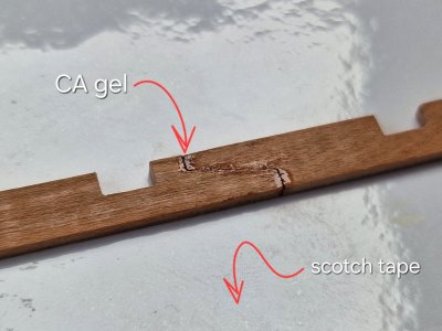
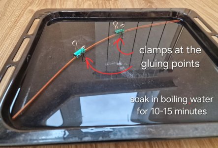
By the way, before that I glued boards without heating, water, steam or iron. But in this situation, the boards go on a screw and it is difficult to keep such tension for a long time. Therefore, at first I gave the boards the correct shape.
View attachment 521668
Only the ends of the boards were dipped in boiling water for a minute and immediately hot irons along the plane, I twisted the board with a screw and bent it a little. But you need not overdo it, otherwise you can break it. Then you definitely need to walk with sandpaper, because lint rises from the water.
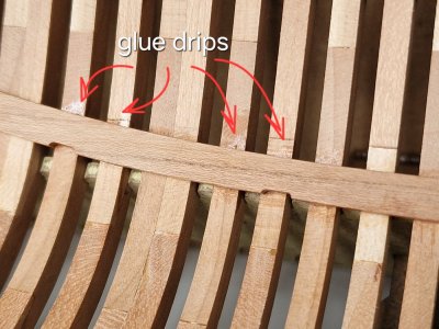
The fixing method is still the same. Point PVA for each frame and CA at the edges. I press the edges while the spouse helps to hold the middle part, and then I still hold it for 5 minutes and you're done. There are no leaks from the glue, and everything is held flawlessly. And here's the result.
View attachment 521669
View attachment 521670
View attachment 521671
View attachment 521672
View attachment 521673
View attachment 521675
Looking like lemon slices, or carom, or melon... well, in short, something edible resembles
View attachment 521677
Next in line are Breast hooks and the top pair of powerboards - Beam shelf\Deck clamp (which, in fact, most likely go as one board).
Don't switch!


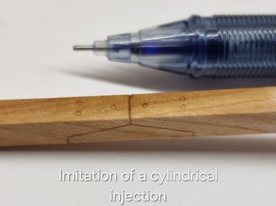
Yes, they should. But I will make imitation bolts, but later, when I sand the outer surface.Hi, I ask, ( I don't remember if I asked already)shouldn't the pieces be nailed down? Frank
View attachment 521872
Thank you very much. I am glad that you are interested. It will be even more interesting.Hey Serikoff,
very nice presentation of your project and very nice detailed presentation of your construction progress. I am interested in your beautiful build and will follow your progress and the beautiful pictures with excitement.
Cheers
Günther
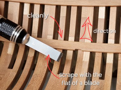
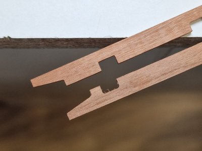
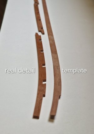
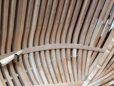
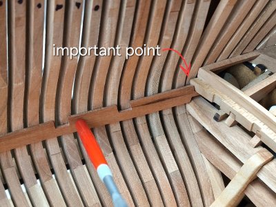
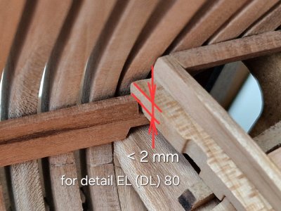
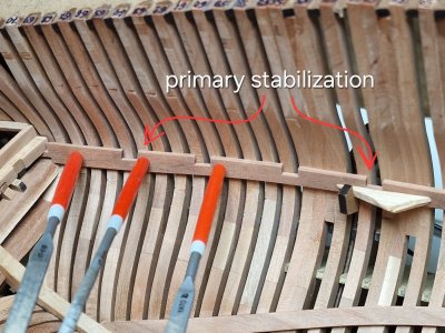
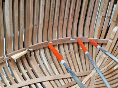
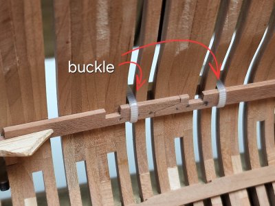
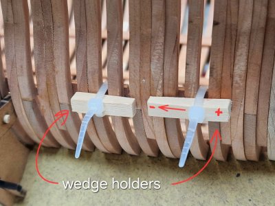
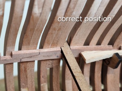

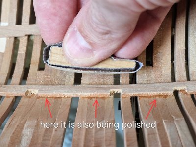
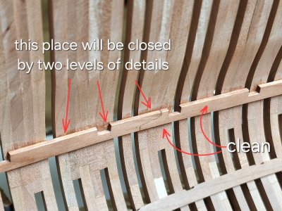
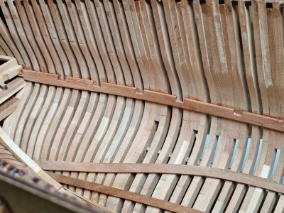
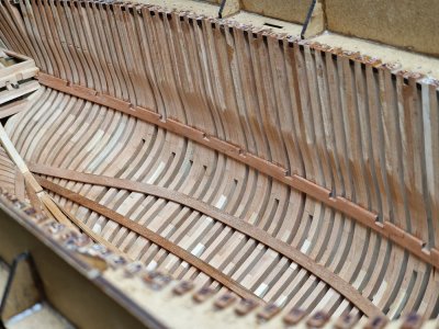
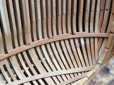
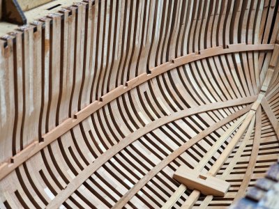

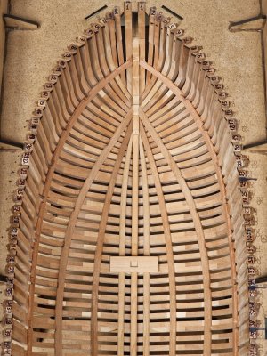
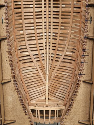



For the Alert the clamps (top belt) would be about 3.5 thick at the top edge and 2.5" at the lower edge. Maybe too much detail for something that will not be seen, but the score that you show in the clamp looks excessive. From (Goodwin, The Construction of the English Man of War, page 66) if the clamp was scored, it would only be about 1 inch, (0.42mm at 1:48) Then again if the beams you have are thicker than what was on the ship the score would have to be deeper than what was actually done to compensate. The upper deck beams on the actual ship would have been moulded about 6.5 to 7 inches (3.4mm to 3.7mm). The drawing of Alert at RMG shows them to be moulded 7" and sided about 10.5" I am curious to know if these are the same as those in the kit.Next up is the top belt, which will hold the main deck beams.
Thank you. I was glad to help.Thanks for the great buildlog! Will be very helpful for me
Dirk
Thank you for your feedback and question. We are currently at war in our country, so I spend all my free time except work on the ship. Since I cannot leave the city, my favorite activity (travel) is currently unavailable to me. Therefore, I spend at least 4-5 hours making the ship almost every day. I can make the ship all day 3 days a week. This is a great alternative to not go crazy from what is happening here. But I hope for the best.Hey Serikoff,
very nice work! May I ask how much time you spend taking care of your model? Also, you write a great build report! I'm really looking forward to your pictures and progress.
Cheers
Günther
Unfortunately, when it comes to terms, the translator translates something incomprehensible. I'm afraid I'll answer incorrectly. Let's do it this way: when I get to the decks, I'll take all the dimensions of the parts of this unit and post them in the description. I hope this will answer your question.For the Alert the clamps (top belt) would be about 3.5 thick at the top edge and 2.5" at the lower edge. Maybe too much detail for something that will not be seen, but the score that you show in the clamp looks excessive. From (Goodwin, The Construction of the English Man of War, page 66) if the clamp was scored, it would only be about 1 inch, (0.42mm at 1:48) Then again if the beams you have are thicker than what was on the ship the score would have to be deeper than what was actually done to compensate. The upper deck beams on the actual ship would have been moulded about 6.5 to 7 inches (3.4mm to 3.7mm). The drawing of Alert at RMG shows them to be moulded 7" and sided about 10.5" I am curious to know if these are the same as those in the kit.
Allan

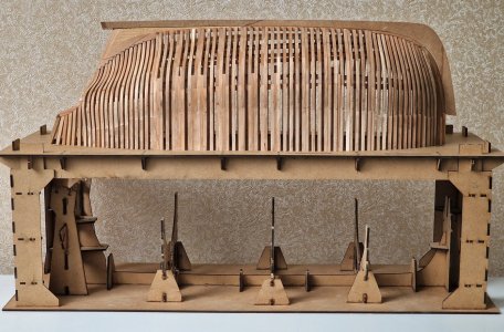



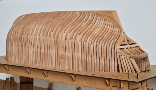
Congratulations with this milestone, Sergey: free op the jig. Now she shows het beautiful lines.Not minutes of rest, we rush on...
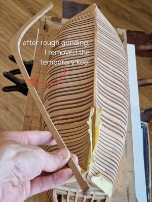
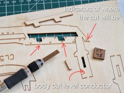
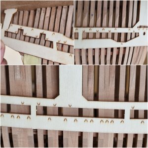
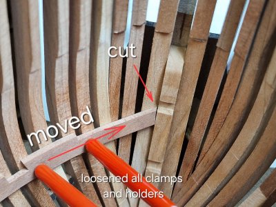
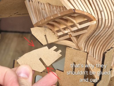
This is why this part does not need to be glued and it is advisable to cut it (as I previously showed it all in the review). Because when removing the ship - these parts are easier to remove. We won't need them anymore.
View attachment 522206
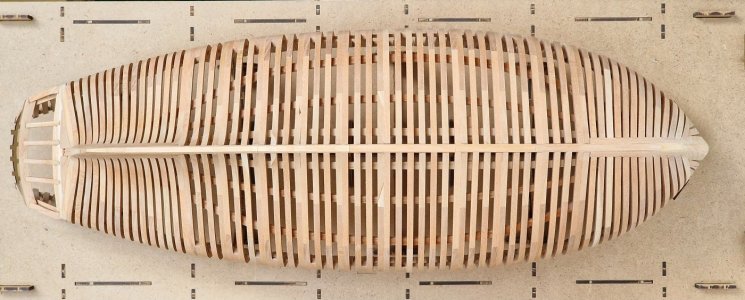
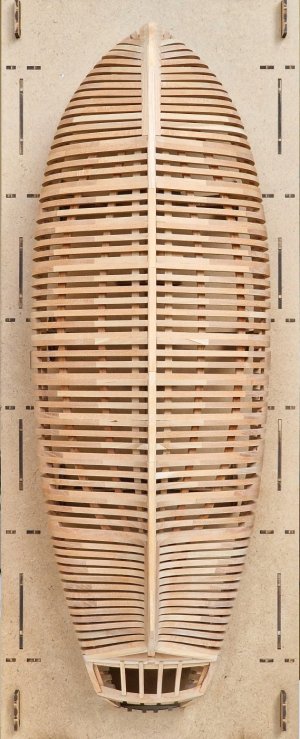
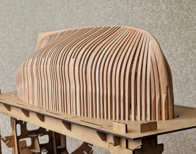
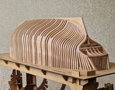
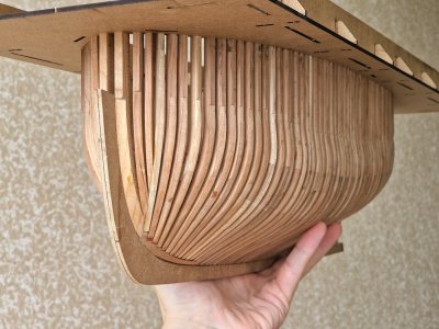
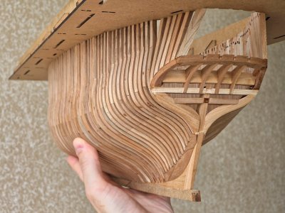
Voila... and the hull is free!
By the way, it is in this form (only without a keel) that it will soon be scanned. I will tell you everything in more detail, but you will remember this picture...
View attachment 522207
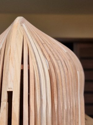
How cool he is after all... The body looks cool in the hand, I really like it... and that's before grinding!
View attachment 522211
View attachment 522212
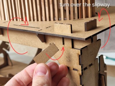
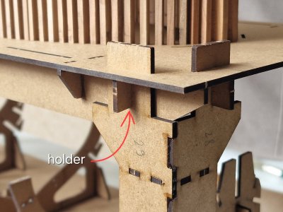
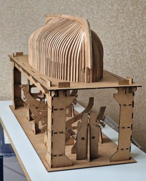
The manufacturer thought out the slipway very well. If you turn over the lid with the model and insert its top with your feet, you can snap the lid with the same clips so that it sits firmly in its place.
View attachment 522213
View attachment 522214
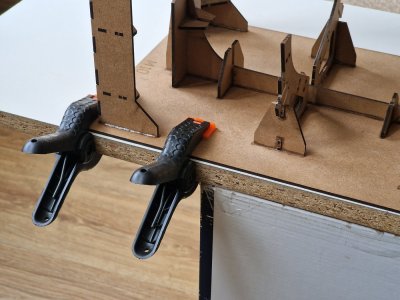
And in this form, you can safely grind the case. A little tip: so that the slipway does not drive around the table - it can be fixed with clothespins or clamps.
View attachment 522227
I could admire this view for a long time, but we continue.
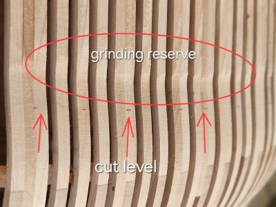
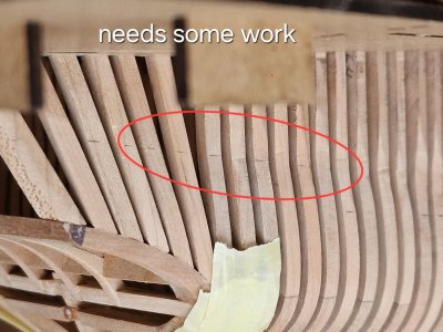
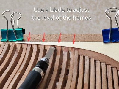
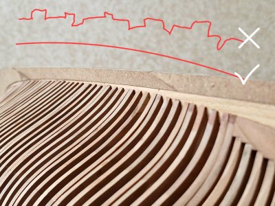
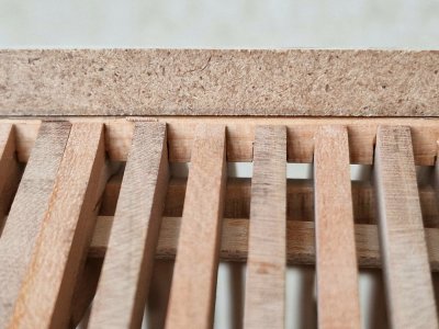
At first, I cut the edges of the frames along the line of the bottom board with a straight blade so that they were one arc, and not different lengths.
View attachment 522217
At the back - there is a template and you can do it using it. And in other places this arc goes along the edge (chamfer) that we did on the false keel.
View attachment 522218
Protectionism is my middle name.
View attachment 522219
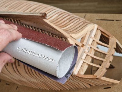
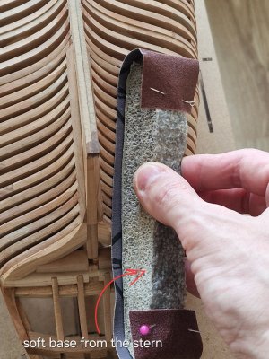
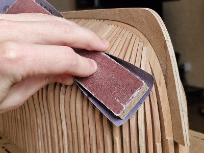
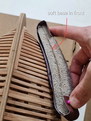
Well, let's go over the grinding technique. It is almost the same as inside, but there are differences.
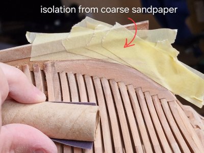
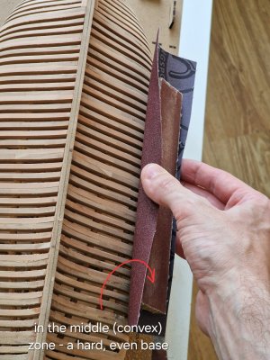
The front and back of the case need to be polished with soft-base sandpaper (insulation for pipes is suitable) as there are concave places.
View attachment 522220
View attachment 522221
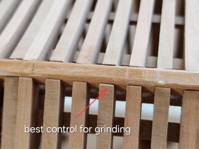
And in the main central part you need a rigid base (wooden beam).
View attachment 522222
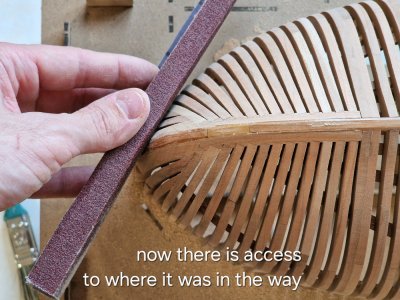
And in places where it is difficult to get to, I put sandpaper several times.
View attachment 522223
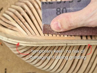
I made a temporary keel not only in order to remove it before scanning, but it also eliminates the risk of damage to a real keel during the grinding process, especially if the grain is large.
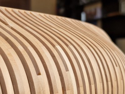
And by the way, about abrasiveness. I use cloth-based sandpaper first grain 80, then 150 and then 240. Or 120 and then 240. Locally some zone can refine 320, but only locally (to remove micro-scratches) where can not get well 240. That's all for now... I think that for 2 days I will grind it and after - I will show the result. Don't switch))
View attachment 522225
View attachment 522226
P.S. in the photo from above - the hull even before grinding.
...
I already want to see the ship's hull in a polished form as soon as possible.Congratulations with this milestone, Sergey: free op the jig. Now she shows het beautiful lines.
Regards, Peter
Cherry is a very dense wood, so the most protruding parts can be 80t, otherwise it can all drag on for a long time. If after that you go through 120 and then 240 everything will be like glass. I can already see the result, it's been tested.Grade 80 on soft hullFor me, anything below 150 is a cheese grater


