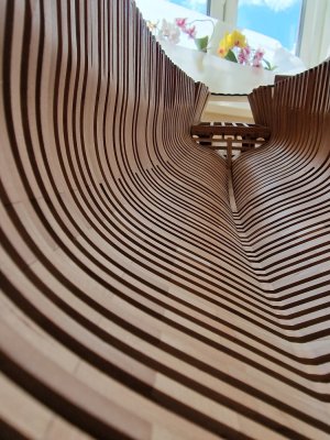
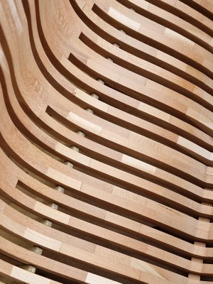
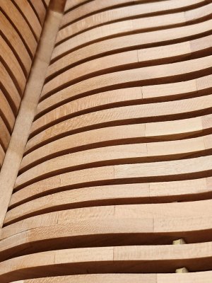
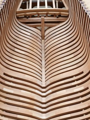
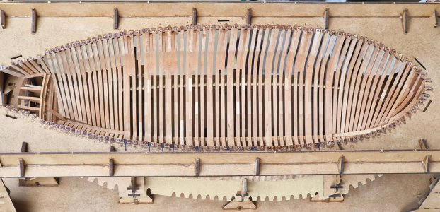
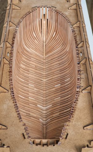
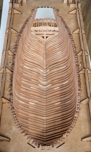
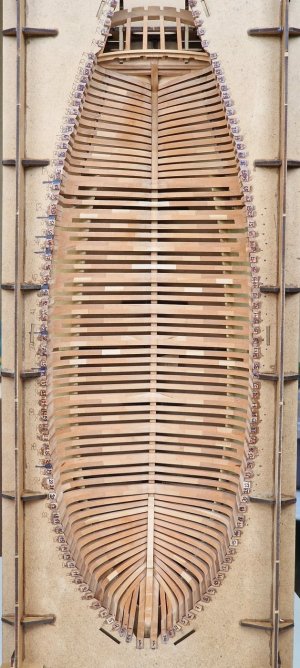
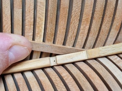
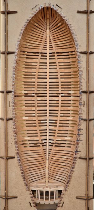
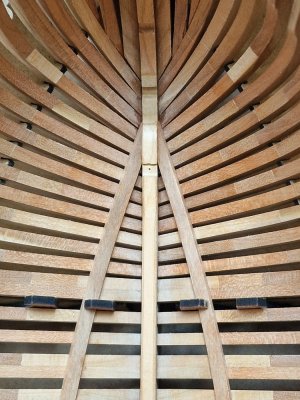
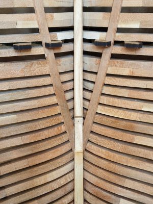
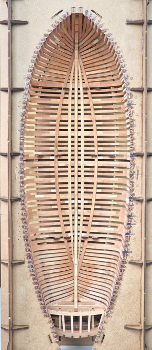
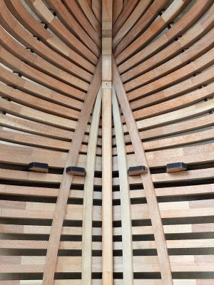
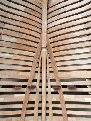
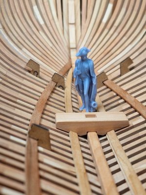
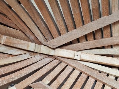
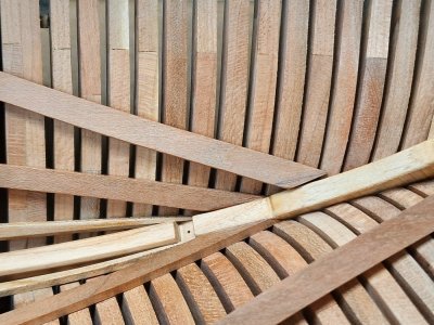
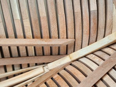
HMS Alert [1777] 1:48 POF by serikoff. (Two hulls: skeleton and fully rigged)

Chapter 4. Decks

The chapter will consist of several parts:

4.1 preparation (sanding of ship hull inner surface),
4.2 basis (laying of power boards under beams),
4.3 sanding of external surface,
4.4 lower deck (fixation of beams),
4.5 upper deck.


4.1 Sanding of ship hull inner surface.

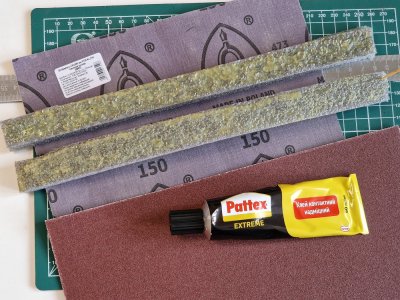
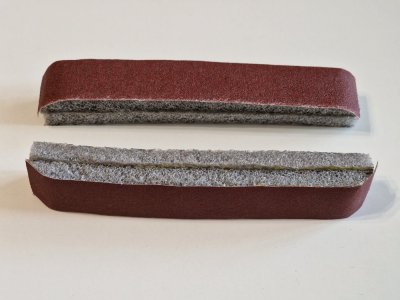
For grinding, I used a pipe insulation material (insulation) by gluing it in half.

Alert 537.jpg

Glued to contact glue (shoe). Smeared, waited 15 minutes - pressed hard, that's it, you can use it.

Alert 538.jpg

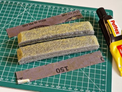
Then, he also glued sandpaper, 150 and 240 grain. And it turned out such tools. The main thing is that the corners of the surface are rounded.

Alert 539.jpg

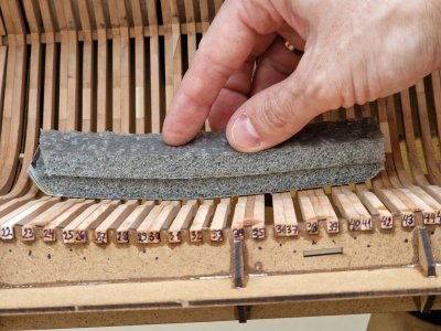
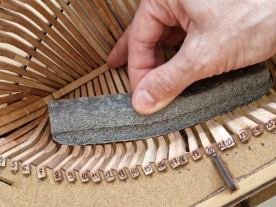
This design allows you to grind concave surfaces, making them perfectly smooth.

Alert 540.jpg

Alert 541.jpg

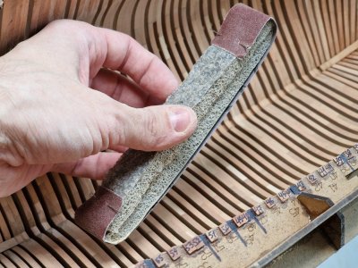
But in order not to glue constantly, but to use all the time new sandpaper, I left the glued ones at the end, and did all the work teasing the canvases to the instrument, from time to time replacing the canvases.

Alert 542.jpg

And already finally polished those that were glued. And the main thing (this is a bonus for those who not only look at pictures, but also read my review) is the main thing - that first you need to grind along the body, and finally - walk along the frames (along the wood fibers). Thus, there will be no traces of sandpaper!

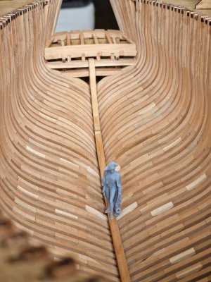
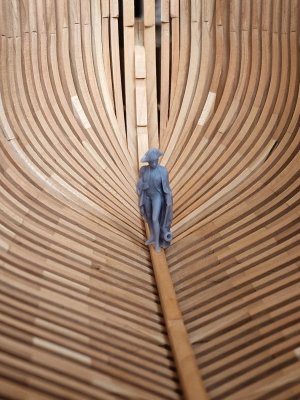
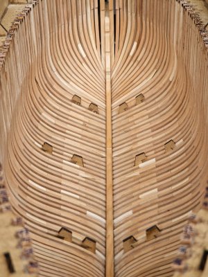
Well, here is the result of a whole day of painstaking work...

Alert 543.jpg

Alert 544.jpg

Alert 545.jpg

Alert 546.jpg

Alert 547.jpg

Alert 548.jpg

Alert 549.jpg

Alert 550.jpg

Alert 551.jpg

Alert 552.jpg

Alert 553.jpg

Alert 554.jpg

Ship-1
 
Chapter 4. Decks

The chapter will consist of several parts:

4.1 preparation (sanding of ship hull inner surface),
4.2 basis (laying of power boards under beams),
4.3 sanding of external surface,
4.4 lower deck (fixation of beams),
4.5 upper deck.


4.1 Sanding of ship hull inner surface.

For grinding, I used a pipe insulation material (insulation) by gluing it in half.

View attachment 521298

Glued to contact glue (shoe). Smeared, waited 15 minutes - pressed hard, that's it, you can use it.

View attachment 521299

Then, he also glued sandpaper, 150 and 240 grain. And it turned out such tools. The main thing is that the corners of the surface are rounded.

View attachment 521300

This design allows you to grind concave surfaces, making them perfectly smooth.

View attachment 521301

View attachment 521302

But in order not to glue constantly, but to use all the time new sandpaper, I left the glued ones at the end, and did all the work teasing the canvases to the instrument, from time to time replacing the canvases.

View attachment 521303

And already finally polished those that were glued. And the main thing (this is a bonus for those who not only look at pictures, but also read my review) is the main thing - that first you need to grind along the body, and finally - walk along the frames (along the wood fibers). Thus, there will be no traces of sandpaper!

Well, here is the result of a whole day of painstaking work...

View attachment 521304

View attachment 521305

View attachment 521306

View attachment 521307

View attachment 521308

View attachment 521309

View attachment 521310

View attachment 521311

View attachment 521312

View attachment 521313

View attachment 521314

View attachment 521315

Ship-1
Equipped with nice sanding tools you have have a very nicely shaped inside, Sergey. A day of sanding was a good investment.
Regards, Peter
 
Witaj
Piękny kadłub z przyjemnością ogląda się twoją relacje Sergey . Pozdrawiam Mirek
Dziękuję. Miło to słyszeć. Cieszę się, że Ci się spodobało.

Beautiful! :-)
Thank you. Let's continue))

Equipped with nice sanding tools you have have a very nicely shaped inside, Sergey. A day of sanding was a good investment.
Regards, Peter
Thank you. I already want to do the same on the outside.
 
4.2 Basis (laying of power boards under beams).

Here are all the details I will need for this section.
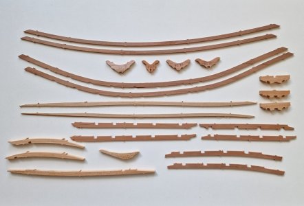
Alert 556.jpg

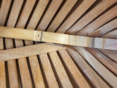
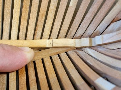
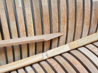
First of all, I glued all the Keelson fragments together. According to the instructions, they need to be glued in turn, but as for me, it is illogical and more difficult to do.

Alert 557.jpg

Glued on the table so that the geometry is not disturbed. Clamps put clerical at the edges from gluing so that the parts do not slide off on the glue. Then he polished all the surfaces and made 90-degree corners in the grooves under Breast hooks.
In the meantime the glue was drying out, I was preparing Mast step parts.
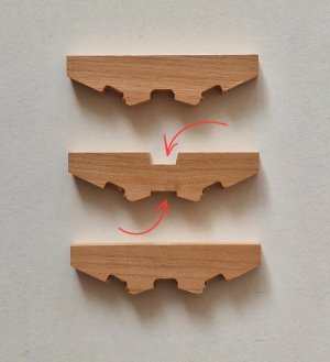
Alert 558.jpg

The middle part is glued on both sides, so it needs to be finalized before gluing, as indicated by the arrows above. This middle section differs not only in the mast notch, but also lower in the central zone. This protrusion will lock into Keelson and position the entire part. And after grinding the planes, I need to glue 3 fragments.
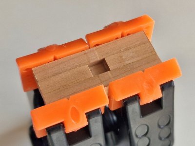
Alert 559.jpg

Without wasting time while the glue dries (5 minutes))) I sanded Limber strike (two power boards closest to the keel).
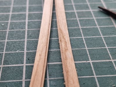
Alert 560.jpg

In order for Keelson to clearly lie on all the frames - it was necessary to make a small device.
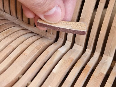
Alert 561.jpg

This is a piece of wood from a 5 mm thick set on which I glued sandpaper.
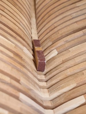
Alert 562.jpg

Since this "tool" with a slight bend, it perfectly grinds the frames along the deflection line. And here is the result, the surface clearly corresponds to Keelson.
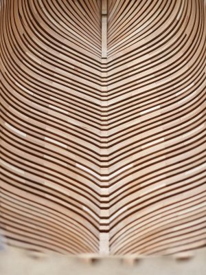
Alert 563.jpg

But before fixing, he needed to create the correct chamfer from above.
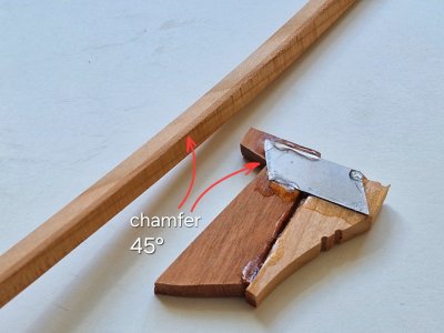
Alert 564.jpg

To make an even uniform cut of 45 degrees, I made such a device in a couple of seconds from a couple of pieces of wood and a piece of blade glued to the SA. Scraping methods can be made a neat bevel, then modified with sandpaper.

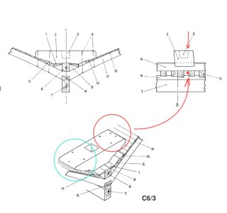
I will continue to constantly make footnotes on anatomy if there are inaccuracies or simplifications in the set. But now is the moment with inaccuracies in the anatomy itself, which relate to the detail of the Mast step.

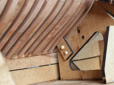
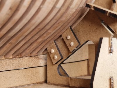
First, the anatomy shows that this part is fixed with 4 bolts on each side, as indicated in the red circle. But then, one of the distant bolts would not fall on the frame, which could not be. Therefore, it is more logical that the bolts hitting all the frames twice were 3 on each side. Since this is a small ship and the effort does not go to the separation but to the displacement, then I think 6 bolts are enough for this unit.
Alert 565.jpg

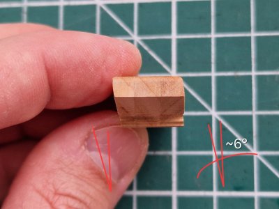
The second moment is the tilt of the front and back walls. As shown in the side view of the drawings, this angle is approximately 6 degrees. I don't know if it will be visible, but it took me half a minute on the grinder - so I did it like in anatomy.
Alert 566.jpg

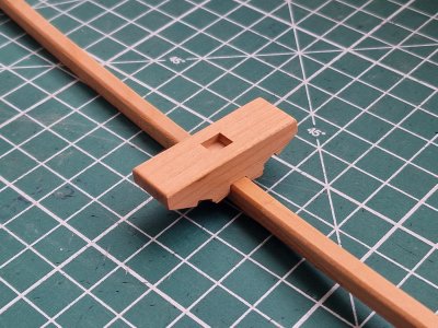
And this is how it looks assembled, front view...
Alert 567.jpg

.. and rear view.

Alert 568.jpg

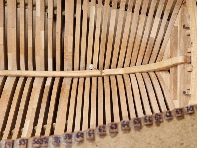
So how I fixed Keelson. Since all these manipulations are fast enough and there is no time for photos, those who read my review - as a bonus - tell this procedure in a step.
Alert 569.jpg

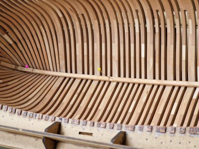
First, I drilled holes in the grooves with a diameter into which the pin passes. And with this mace he fixed the part in place. There are three such places.
Alert 570.jpg

Then I applied PVA TiteBond from a syringe to each frame. (Be sure to point out that during compression the drop occupies only the gluing zone without staining everything around. I remind you that the oil does not lie well where there is a surplus of PVA. You need to apply pointwise and at the same time without rubbing, so as not to waste time on this and the glue did not have time to dry. And when the parts are compressed, the drop will spread along the gluing plane anyway).

Then, from the stern, I applied a strip of CA to Keelson himself. The pin next to the glue must be threaded through in order to insert its tip into the keel and lower the Keelson into its place along the pin. This makes it easier to position it with a fast glue.

For now, while the CA glue sets, the entire Keelson is laid on the frames, parailly passing pins into the holes for better positioning of the second edge. Well, all that remains is to hold Keelson so that the caday is completely frozen (5-7 minutes). And here is the finished result.
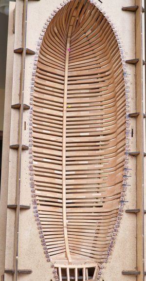
Alert 571.jpg

Well, as always now, Nelson, once again inspects the result of the fixation. ROTF

Alert 572.jpg

Alert 573.jpg
...
 
While there is an opportunity, I will immediately add this part...

Of the 4 pairs of powerboards, the instruction recommends starting to glue with Limber strike, these are the closest to the keel. But logically, in order for everything to work out as symmetrically as possible, you need to start with the second. This is the one out of three that are in contact with each other - the average. And starting from it - you can glue both higher and lower.

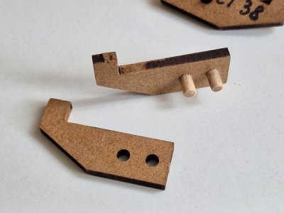
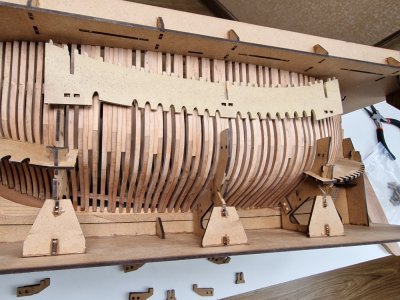
But for this you need to add elements to the slipway. These are hook positioners for 3 pairs of power boards.

Alert 574.jpg

Before fixing, I cleaned a little from the soot of the place of contact with the boards and made pins for fixing from a 3mm cylindrical workpiece.

Then I temporarily removed the middle part of the side positioners to make access to the attachment point.

Alert 575.jpg

After that, it was possible to fix the "hooks" on the pins.

Alert 576.jpg

Alert 577.jpg

Fixed so far 2 lower levels. I will fix the upper one later. And this is how it all looks.

Alert 578.jpg

As you guessed, these positioners are needed in order to accurately place the power boards on the case.

Parts DL 30 (Trickstuff over the floor heads) Longer and therefore they need to be adjusted according to the meter. Better to start from the front. The end of these parts must be at the Keelson termination point (BL12).

Alert 579.jpg

We remove the excess and take into account that the rail goes at an angle, so the slice should be with this calculation.

Alert 580.jpg

That is, when we press, the gluing planes must converge. I will show you in more detail below using the example of the back.

So the opposite end, the stern side.

Alert 581.jpg

The rail is longer, we will cut it so that its end falls on the connection of the BL15 and ID14 parts (a small step).

Alert 582.jpg

We cut again and take into account the angle of rotation of the rack. The board should have this end.

Alert 583.jpg

And when pressed - the planes for gluing should converge without a gap and the end of the part should reach the step on the keel.

Alert 584.jpg

This is important in order for the top and bottom boards to dock correctly and in the right place. And here is the result after fixing.
Symmetry is our everything!

Alert 585.jpg

Alert 586.jpg

Alert 587.jpg

For those who are interested in how to stick just as symmetrically and without glue spots and leaks, and most importantly quickly - here's my experience.

First, I put the board in the hooks and then shifted it half its width higher along the frames. This is necessary to put dots with a pencil along the entire length of the board. That is, when we shifted it, we visualized exactly the center of the board.

Then I shifted the board even higher (along the frames) so that it was held only by the ends of the hooks.

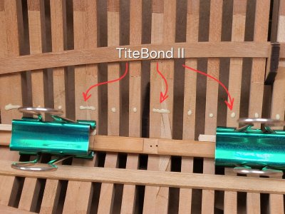
Then I applied a drop of glue from a syringe to each frame, PVA TiteBond II to the dots that we had previously drawn with a pencil. And immediately applied glue CA gel on both ends of the board (those that we had previously polished).

Then the board is neatly shifted to its place, positioned at the ends and pressed well near the place of CA glue with your thumbs. The remaining fingers press the middle part of the board. The CA glue sets quickly, so after a couple of minutes we transfer all the effort to the middle part and hold it for another 5-7 minutes. That's all! You can still stick wedges between the board and hooks in parallel, this will reduce the number of places where you need to press your fingers.

Alert 588.jpg

The method is working. Fast and most importantly - neat. Since the only place where the glue can come out a little is CA gel, but it will be perfectly scraped with a blade and removed without a trace with fine sandpaper. And unlike PVA, it does not change color after coating with oil. And the point-spread PVA does not go beyond the glue stain and does not give leaks. Which makes me very happy. ;)
...
 
The second pair of boards already exists, now we will glue the first pair (those closer to the keel, Limber strike).
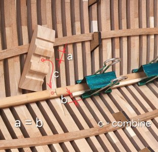
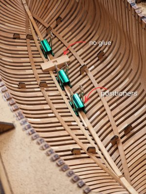
And to position the boards in the exact place, I used the stationery clips, plus wood (b - in the photo below). Which corresponds to the distance from the keel to the boards on the Mast step (a - in the photo). By the way, on the Mast step there is a ledge (with - in the photo) that needs to be combined with a chute on the keelson.

Alert 589.jpg

And now, you can glue the boards and just rest against the clips, and they will be glued evenly.

Alert 590.jpg

By the way, the gluing technique is the same. I dot the TiteBond II glue on each frame, except for the most lateral ones. I apply CA gel on the bottom. My wife helps me. While I hold the CA point - it holds the board over the PVA. And as soon as the CA sticks, I hold the place where the PVA was for another 5 minutes and everything is ready. Fixation without devices takes 6-7 minutes and you can work further.

Alert 591.jpg

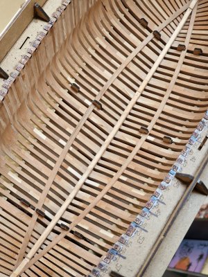
And here is the finished symmetrical result.

Alert 592.jpg

Alert 593.jpg

Alert 594.jpg

And after that I glued the Mast step.

Alert 595.jpg

Next in line is the third pair of powerboards. Anatomically, this is most likely Upper strike of thickstuff footwaling, but the thickness and width of the board from the set are combinations of the aforementioned and Thickstuff over first futtock heads. (whatever that means)))

It is better to adjust them also from the front.

Alert 596.jpg

We still remember that the board is spinning in a spiral and you need to make a bevel in order to press it like this without a gap. And the joint hit as in the photo.

Alert 597.jpg

But you need to take into account a very vague moment. The ket includes a positioner (part CL 46).
It is necessary that this part passes between the 22th and 23th frames and gets into the groove for the 3rd beam of the lower holly. That is, you need to adjust the board in front so that this happens!

Alert 598.jpg

Well, at the back, similarly, we also cut off until we connect with the second pair of power boards. again, not forgetting the bevel.

Alert 599.jpg

Alert 600.jpg

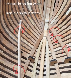
By the way, before that I glued boards without heating, water, steam or iron. But in this situation, the boards go on a screw and it is difficult to keep such tension for a long time. Therefore, at first I gave the boards the correct shape.

Alert 602.jpg

Only the ends of the boards were dipped in boiling water for a minute and immediately hot irons along the plane, I twisted the board with a screw and bent it a little. But you need not overdo it, otherwise you can break it. Then you definitely need to walk with sandpaper, because lint rises from the water.

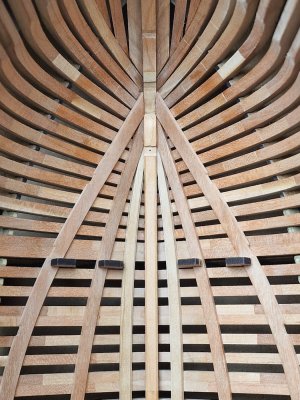
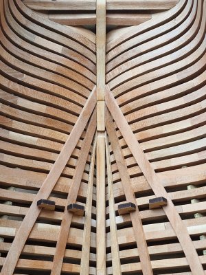
The fixing method is still the same. Point PVA for each frame and CA at the edges. I press the edges while the spouse helps to hold the middle part, and then I still hold it for 5 minutes and you're done. There are no leaks from the glue, and everything is held flawlessly. And here's the result.

Alert 603.jpg

Alert 604.jpg

Alert 605.jpg

Alert 606.jpg

Alert 607.jpg

Alert 608.jpg

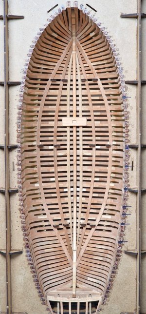
Looking like lemon slices, or carom, or melon... well, in short, something edible resembles ROTF :p

Alert 609.jpg

Next in line are Breast hooks and the top pair of powerboards - Beam shelf\Deck clamp (which, in fact, most likely go as one board).
Don't switch! ;)
 
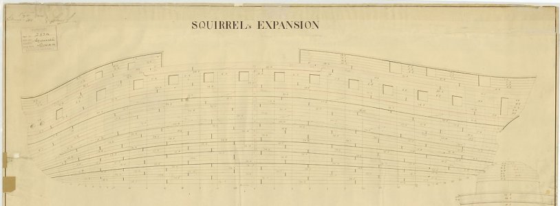
It is interesting to note that the drawings of Squirrel and Sphinx below show all but two or three of the internal strakes of planking end at the keelson or stem.
Allan

1748177134156.jpeg
1748177265436.jpeg
 
Witaj
Pięknie to zrobiłeś i opisałeś. Pozdrawiam Mirek
Dziękuję. Cieszę się, że Ci się spodobało.

Fantastic, precise work.
Thanks a lot!
It is interesting to note that the drawings of Squirrel and Sphinx below show all but two or three of the internal strakes of planking end at the keelson or stem.
Allan

View attachment 521751
View attachment 521752

These ships are bigger. The smaller cutters with a diagonal keel were probably like that. But there is no drawing of these power boards in the anatomy. You have to trust the manufacturer of the kit and do as in the instructions.
 
You have to trust the manufacturer of the kit and do as in the instructions.
I hope this is a case where we can agree to disagree. :)

Accepting that the planking was indeed different I wonder at what size a ship's internal planking changed. If you look at the internal planking expansion of a 14 gun sloop in the 18th century, the planking is the same as the expansions of larger vessels shown above but even this size ship would be substantially longer than a 10 gun cutter. If it was different for a 10 gun cutter, brig, or sloop I wonder why it would be different.

In the end, your planking is neatly done and your model is impressive to say the least. Kudos!
Allan
As always - translation difficulties. I wanted to say that since the manufacturer decided to do it this way, we have no choice to do it differently. Or rather, it goes and is, but there is no illustration of this moment in the anatomy, so I left it as is. I have questions about multiple wedges in the casing, but that's it. :)Thank you for your assessment.;)
 
Back
Top