3.4 Front frames (adjustment and fixation).
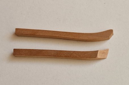
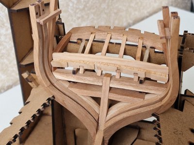
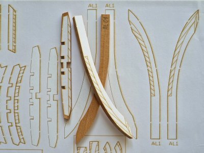
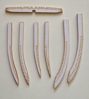
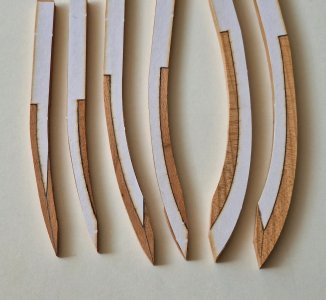
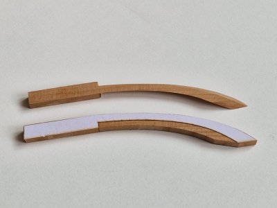
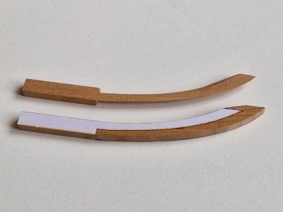
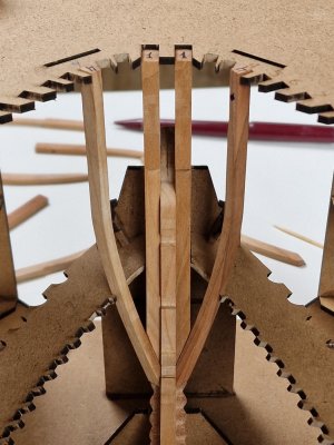
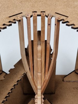
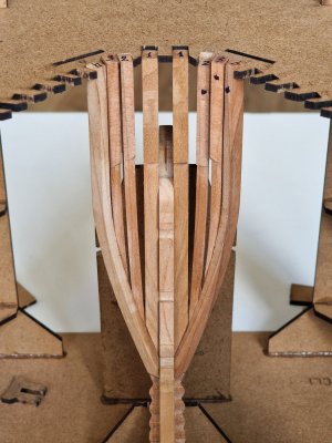
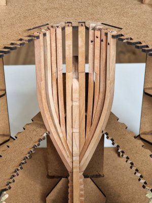
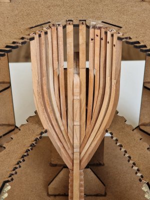
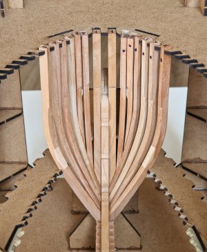
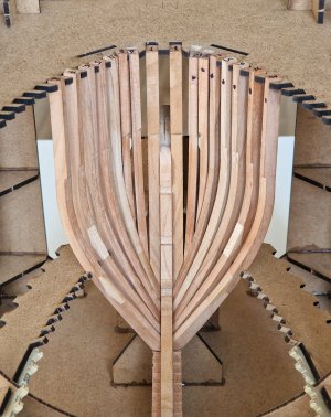
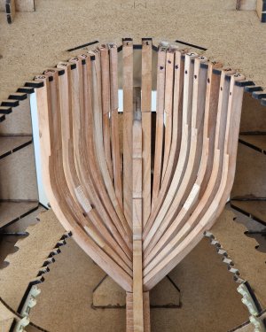
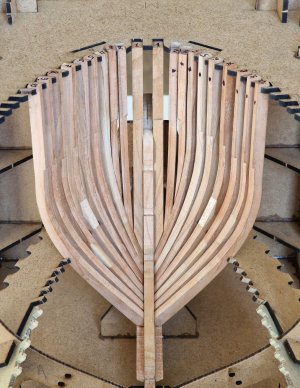
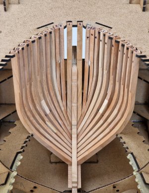
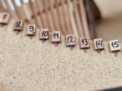
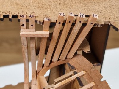
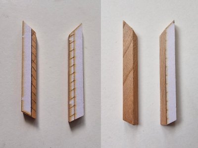
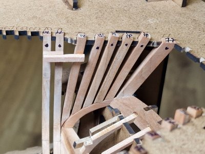
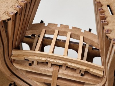
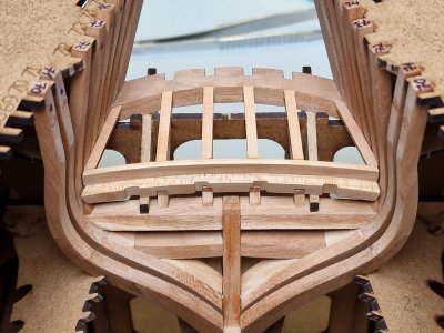
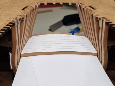
I have finished work on the stern so far and I will return to it later. In the meantime, I will make the front frames. The first 3 pairs have a special shape and you need to make it by stickers.
View attachment 519518
View attachment 519519
View attachment 519520
View attachment 519521
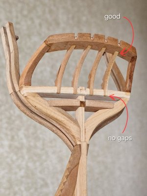
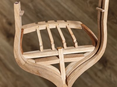
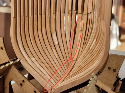
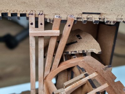
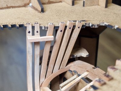
There are no particular difficulties in this. But the place of contact with frame 4 is very important. And it needs to be adjusted so that a gap does not form. Therefore, I do not recommend immediately polishing this place completely, but repeatedly checking.
View attachment 519522
View attachment 519523
It is also important that these two parts fit snugly together.
View attachment 519524
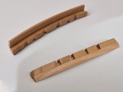
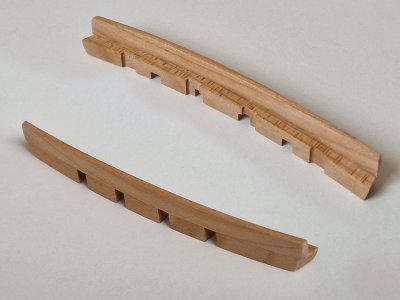
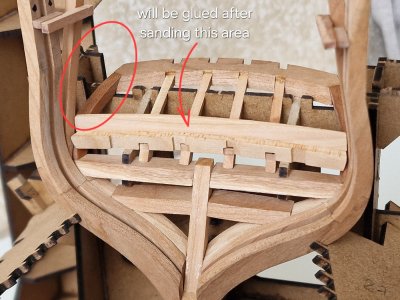
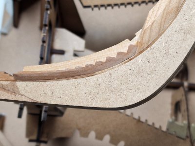
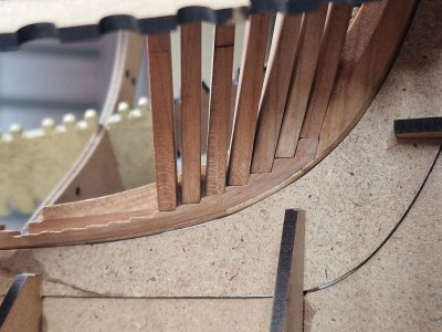
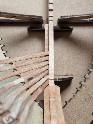
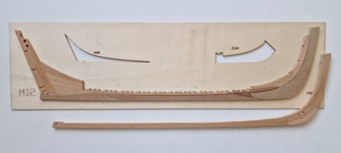
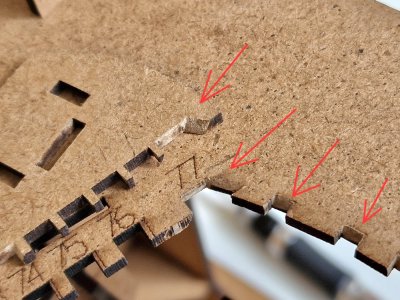
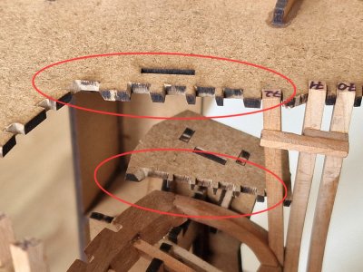
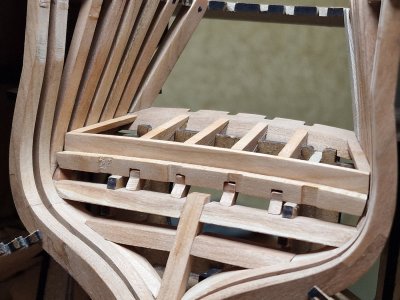
By the way, these lower combs, on which the frames will rest, are not the final shape. They need to be customized for each frame. Especially with the first 5-6s. Therefore, I still have not glued the case to the slipway, and I still have the opportunity to take it out and adjust it in a more convenient position, access and visibility.
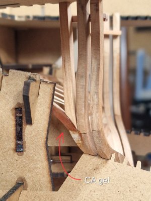
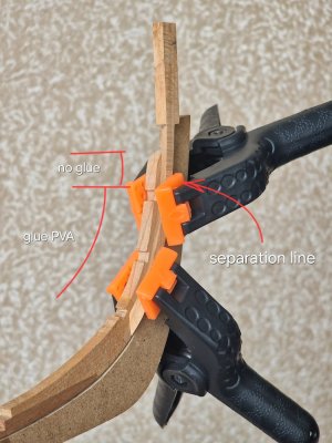
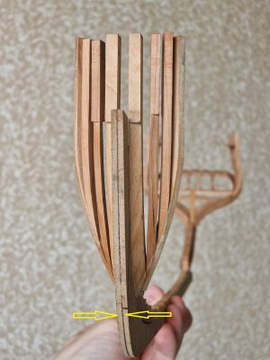
After checking, I glued frames number 1 not in the slipway, controlling the position of the arc with the arc of the false keel. Importantly, there is no need to apply glue to the entire contact point! Since after cutting the frame it will be difficult to tear it off where the glue was.
View attachment 519525
View attachment 519526
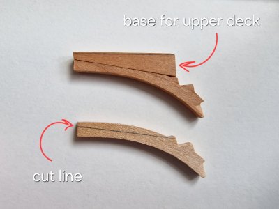
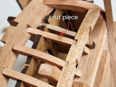
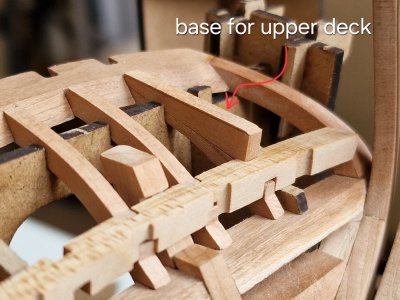
Looking ahead, I want to show how the part should look like under the front frames. It was so cut not at one time, but by the method of selection, edits and micro-cuts after each frame.
View attachment 519527
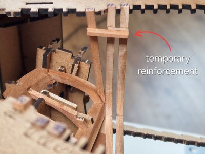
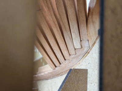
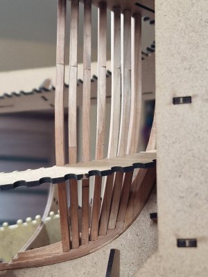
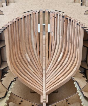
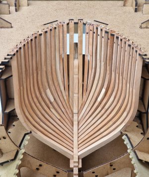
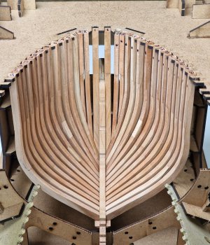
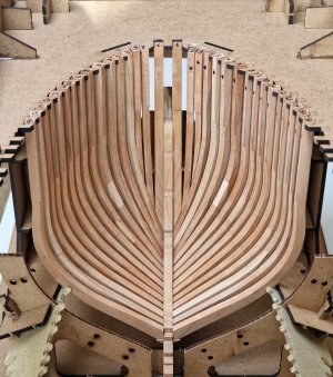
And this is how the installed frames look dry (without glue). I recommend that you first adjust several frames and check the contours, and only then glue. This will save you from hollows if you incorrectly fit some frame and it will be out of place.
View attachment 519528
View attachment 519529
View attachment 519530
View attachment 519531
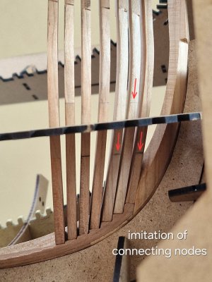
Earlier in the review, I said that I would do imitation of connections on 4, 5, 6 pairs of frames. Since they are in the anatomy and even in the instructions, but for some reason they were simplified in manufacture. I don't want to redo them, so imitation of connections is my option.
Here is a link to a description of the method...
When I set a few frames, I could see the logical position of the connections on the front pairs. I drew lines with a pencil and they will be landmarks for the position of the cuts. I repeated the same operation inside the case.
View attachment 519532
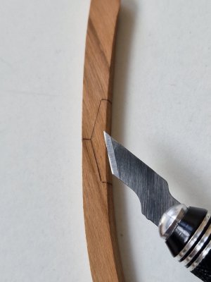
In short, I first draw the outline of the connection...
View attachment 519533
Then I make an incision with a special scalpel. Only I do not lead the cutting cream (you can accidentally make the cut larger, and the pressure is difficult to control), and I push the entire sharp plane along the entire length of the line. Just this line is the same as the length of the scalpel.
View attachment 519534
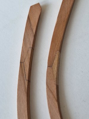
Below are examples (not the most indicative) but you can understand the principle from them.
View attachment 519535
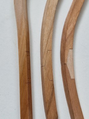
On the right is a real connection. In the center - imitation. On the left is also imitation, but under oil and with imitation bolts. (not very visible, but the live lines are very similar to glue joints).
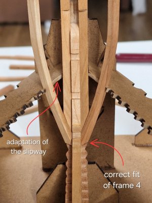
The first frame that needs to be glued is the 4th. It has no notes on how to grind it, so this is achieved empirically.
View attachment 519536
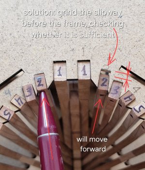
Also, to position 2x and 3x frames, you need to polish the slipway a little.
By the way, about the 2nd frame.
View attachment 519537
ATTENTION UPDATE:
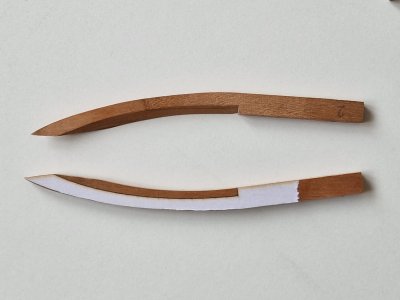
On the inner surface, you can adhere to grinding by stickers...
... but the outer part should NOT be processed like this (as the stickers recommend)!!!
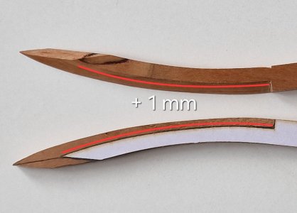
Unfortunately, although I said not to trust the stickers, I ground them along their contour, but you need to leave at least 1 mm more on the outside, as shown in the photo below with a red line.
View attachment 519596
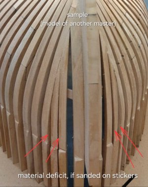
If you process as the stickers show, you get a difference in the material, and after grinding there will be holes and holes like on this sample of another master.
View attachment 519597
The solution became - grinding the slipway and tilting the second frames forward to compensate for this deficit. Surprisingly, this will not affect the inner surface.
View attachment 519598
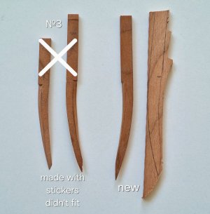
But with the 3rd frame, everything is not so simple. According to stickers - the form did not fit at all.
View attachment 519539
And I had to redo those details twice. But by the method of numerous adjustments, I did as much as I could.
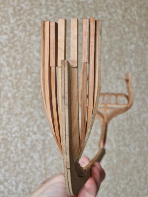
And running ahead, after I took the case out of the slipway, this is what happened.
View attachment 519540
I achieved maximum symmetry and predicting the final grinding I think that the body will be with the correct contours, without dips. But since I have not yet glued the frames to the slipway, I will slightly tilt the upper ends of the 2x frames forward to surely achieve the correct shape.
...
. Seriously tho it will be an amazing help to future Alert builders. Your wood work is so clean as well.
.


