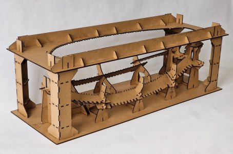
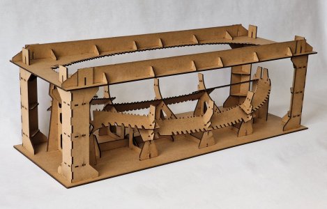
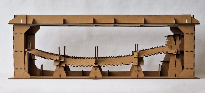
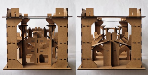
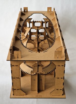
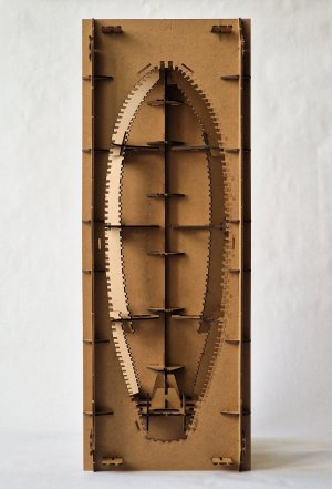
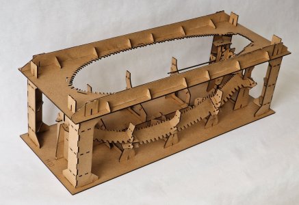
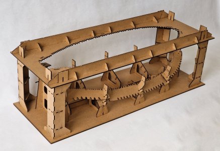
Thank you very much. A few more steps and you can glue it and then the base will be even stronger)) I can't wait to fix the frames, but for this I still need to make a frame.A very nice explanation and outcome, Sergey. A solid base!
Regards, Peter
-

Win a Free Custom Engraved Brass Coin!!!
As a way to introduce our brass coins to the community, we will raffle off a free coin during the month of August. Follow link ABOVE for instructions for entering.
-

PRE-ORDER SHIPS IN SCALE TODAY!
The beloved Ships in Scale Magazine is back and charting a new course for 2026!
Discover new skills, new techniques, and new inspirations in every issue.
NOTE THAT OUR FIRST ISSUE WILL BE JAN/FEB 2026
- Home
- Forums
- Ships of Scale Group Builds and Projects
- HMS Alert 1777 1:48 PoF Group Build
- HMS Alert 1777 1:48 Group Build Logs
You are using an out of date browser. It may not display this or other websites correctly.
You should upgrade or use an alternative browser.
You should upgrade or use an alternative browser.
HMS Alert [1777] 1:48 POF by serikoff. (Two hulls: skeleton and fully rigged)
2.5 Rework (grooves, holes and XVIII)
As I showed above, the BL6 detail needs to be finalized, but... the method that, according to the instructions, is a little more complicated than what I did. Plus, in my method, I was able to eliminate the hole that appeared due to an error in the size of the parts.
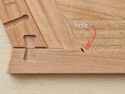
I cut some of that detail along the line of the bottom skin board...
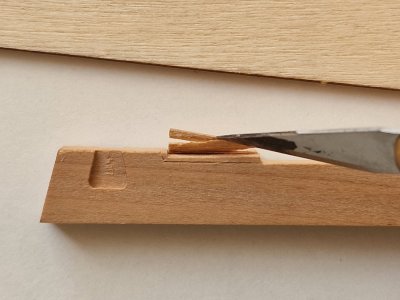
... and the result is a slightly larger hole ))) ...
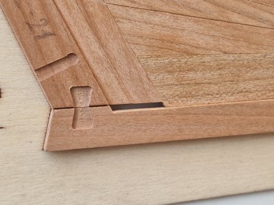
And then I glued a piece of wood to the false keel...
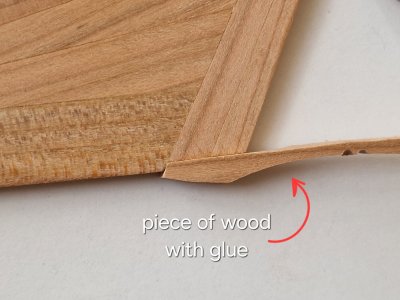
... and after fitting...
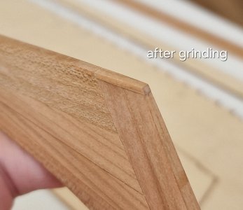
... it turned out like this.
The next refinement was the holes for the deadeye stay. Since I was redoing the part, I decided to do the holes correctly. And again a little theory.
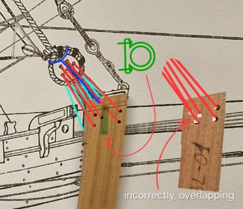
In short: the holes should not be exactly in the center of the part, since there is a metal bowsprit holder. And also the holes should not be one after another, since the ropes will then go along the same line and overlap, wedge and grind each other. Therefore, they must go radially at approximately the same distance.
Plus the holes are too big.
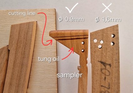
On the sampler, I made not only holes and covered with oil, but also made decorative lines.
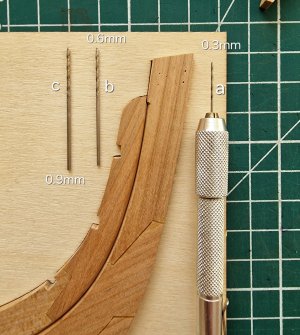
It is better to make holes starting from a small diameter and raise. Controlling the parallelism and accuracy of the exit from the other side.
I made stripes with a knife.
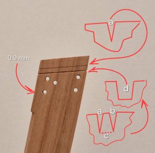
The top thin line is simply a cut with scalpel (s). The lower one is more complicated. You need to make two cuts (a, b), and then carefully remove the tree between them (c) and you get a larger cut (d).
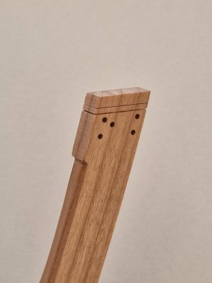
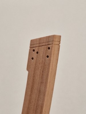
Well, here's the result:
The third revision was the Latin figures of the ship's draft.
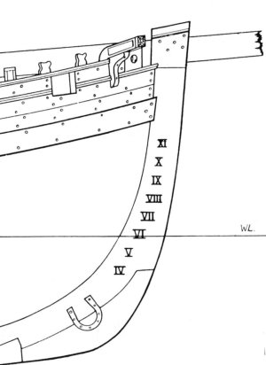
On small ships, these numbers were on the front of the ship on both sides and went parallel to the waterline along the arc of the skin.
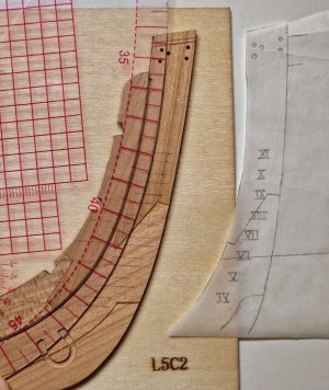
To do this, I made a small stencil, calculated the distance between the numbers and drew parallels on which the numbers will be applied. And with the help of a ruler for cutting, he drew an arc. And applied numbers.
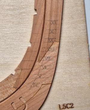
Then he cut out their silhouette very carefully with a knife. I recommend cutting each line twice. Above and then below and, as it were, bringing them together. Thus, there will be no risk of drawing a line further than it should be and the section will be of the same thickness.
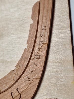
I used tape to transfer the position to the other side. When peeling it off, it leaves all the markings on itself and then you just need to lean the tape (not with the adhesive side) and put dots on the sides of the lines. And then just draw those lines between points. And since the tape is positioned in the same way as on the other side, the entire markup will be mirrored (the main number cannot be made mirrored))
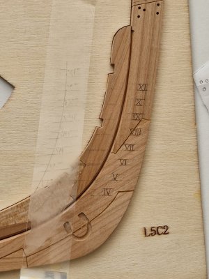
Then you need to erase the pencil and you're done...
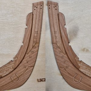
Of the improvements, it remains only to adjust the landing meta for metal parts and you can glue both keels.

As I showed above, the BL6 detail needs to be finalized, but... the method that, according to the instructions, is a little more complicated than what I did. Plus, in my method, I was able to eliminate the hole that appeared due to an error in the size of the parts.

I cut some of that detail along the line of the bottom skin board...

... and the result is a slightly larger hole ))) ...

And then I glued a piece of wood to the false keel...

... and after fitting...

... it turned out like this.

The next refinement was the holes for the deadeye stay. Since I was redoing the part, I decided to do the holes correctly. And again a little theory.

In short: the holes should not be exactly in the center of the part, since there is a metal bowsprit holder. And also the holes should not be one after another, since the ropes will then go along the same line and overlap, wedge and grind each other. Therefore, they must go radially at approximately the same distance.
Plus the holes are too big.

On the sampler, I made not only holes and covered with oil, but also made decorative lines.

It is better to make holes starting from a small diameter and raise. Controlling the parallelism and accuracy of the exit from the other side.
I made stripes with a knife.

The top thin line is simply a cut with scalpel (s). The lower one is more complicated. You need to make two cuts (a, b), and then carefully remove the tree between them (c) and you get a larger cut (d).
Well, here's the result:


The third revision was the Latin figures of the ship's draft.

On small ships, these numbers were on the front of the ship on both sides and went parallel to the waterline along the arc of the skin.

To do this, I made a small stencil, calculated the distance between the numbers and drew parallels on which the numbers will be applied. And with the help of a ruler for cutting, he drew an arc. And applied numbers.

Then he cut out their silhouette very carefully with a knife. I recommend cutting each line twice. Above and then below and, as it were, bringing them together. Thus, there will be no risk of drawing a line further than it should be and the section will be of the same thickness.

I used tape to transfer the position to the other side. When peeling it off, it leaves all the markings on itself and then you just need to lean the tape (not with the adhesive side) and put dots on the sides of the lines. And then just draw those lines between points. And since the tape is positioned in the same way as on the other side, the entire markup will be mirrored (the main number cannot be made mirrored))

Then you need to erase the pencil and you're done...

Of the improvements, it remains only to adjust the landing meta for metal parts and you can glue both keels.

Very skillful carving of the numbers, Sergey!
Thank you! I just didn't breathe at that moment))))Very skillful carving of the numbers, Sergey!
Nicely made details and explanations, Sergey.2.5 Rework (grooves, holes and XVIII)
As I showed above, the BL6 detail needs to be finalized, but... the method that, according to the instructions, is a little more complicated than what I did. Plus, in my method, I was able to eliminate the hole that appeared due to an error in the size of the parts.
View attachment 515183
I cut some of that detail along the line of the bottom skin board...
View attachment 515184
... and the result is a slightly larger hole ))) ...
View attachment 515185
And then I glued a piece of wood to the false keel...
View attachment 515186
... and after fitting...
View attachment 515187
... it turned out like this.
View attachment 515188
The next refinement was the holes for the deadeye stay. Since I was redoing the part, I decided to do the holes correctly. And again a little theory.
View attachment 515189
In short: the holes should not be exactly in the center of the part, since there is a metal bowsprit holder. And also the holes should not be one after another, since the ropes will then go along the same line and overlap, wedge and grind each other. Therefore, they must go radially at approximately the same distance.
Plus the holes are too big.
View attachment 515190
On the sampler, I made not only holes and covered with oil, but also made decorative lines.
View attachment 515191
It is better to make holes starting from a small diameter and raise. Controlling the parallelism and accuracy of the exit from the other side.
I made stripes with a knife.
View attachment 515192
The top thin line is simply a cut with scalpel (s). The lower one is more complicated. You need to make two cuts (a, b), and then carefully remove the tree between them (c) and you get a larger cut (d).
Well, here's the result:
View attachment 515193
View attachment 515194
The third revision was the Latin figures of the ship's draft.
View attachment 515195
On small ships, these numbers were on the front of the ship on both sides and went parallel to the waterline along the arc of the skin.
View attachment 515196
To do this, I made a small stencil, calculated the distance between the numbers and drew parallels on which the numbers will be applied. And with the help of a ruler for cutting, he drew an arc. And applied numbers.
View attachment 515197
Then he cut out their silhouette very carefully with a knife. I recommend cutting each line twice. Above and then below and, as it were, bringing them together. Thus, there will be no risk of drawing a line further than it should be and the section will be of the same thickness.
View attachment 515198
I used tape to transfer the position to the other side. When peeling it off, it leaves all the markings on itself and then you just need to lean the tape (not with the adhesive side) and put dots on the sides of the lines. And then just draw those lines between points. And since the tape is positioned in the same way as on the other side, the entire markup will be mirrored (the main number cannot be made mirrored))
View attachment 515199
Then you need to erase the pencil and you're done...
View attachment 515200
Of the improvements, it remains only to adjust the landing meta for metal parts and you can glue both keels.

Regards, Peter
I just have an emotional swing in recent days... And I have good news and bad news.... But more on that later, but for now a bit of refinement...
From what remains to make seats for metal parts.
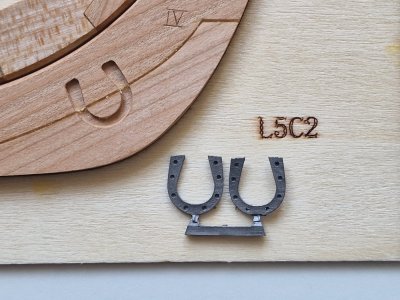
Front is two horseshoes for our horse)))
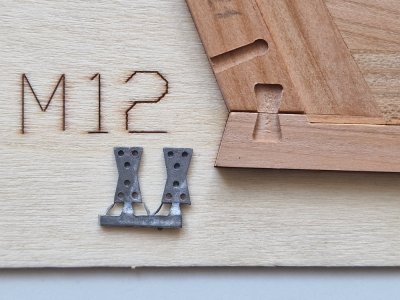
Behind - two "hourglasses".
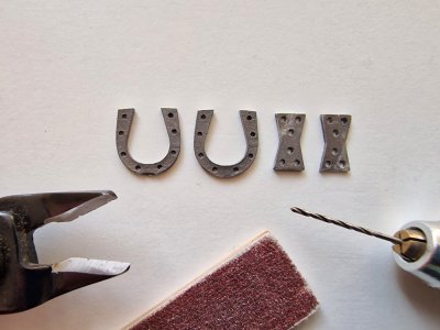
All of them are with holders that had to be bitten off with nippers, adjust the geometry with abrasive and drill holes (since on the horseshoes - they were all not through, I did not touch them yet, but on the "clock" most of them are through, because they were drilled those that were closed).
But naturally, all these details did not fall into place...

Since the milling cutter makes the corners rounded, it was necessary to make them correct geometry, as on parts. I processed the curved lines with boron...

And flat surfaces - with a scalpel. And after that, the "horseshoe" sat tightly in its place.
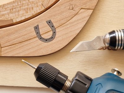
With the rear part similarly.
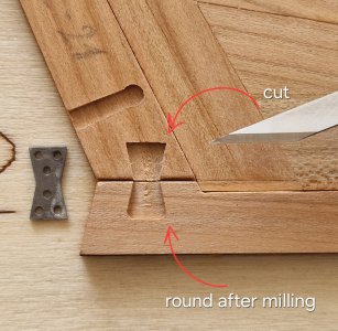
It was necessary to sharpen the corners with a scalpel and everything fell into place.
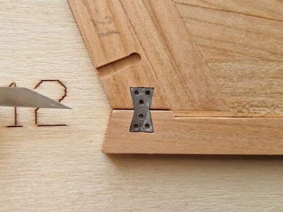
This is the end of the keel job. (P.S. metal parts are deposited back into the cache.) There are 4 more parts that I will do next, but I will not glue it yet, I will leave it in the slipway at the time of assembly.
Well, now the cry of the soul and my emotional swing...

From what remains to make seats for metal parts.

Front is two horseshoes for our horse)))

Behind - two "hourglasses".

All of them are with holders that had to be bitten off with nippers, adjust the geometry with abrasive and drill holes (since on the horseshoes - they were all not through, I did not touch them yet, but on the "clock" most of them are through, because they were drilled those that were closed).
But naturally, all these details did not fall into place...

Since the milling cutter makes the corners rounded, it was necessary to make them correct geometry, as on parts. I processed the curved lines with boron...

And flat surfaces - with a scalpel. And after that, the "horseshoe" sat tightly in its place.

With the rear part similarly.

It was necessary to sharpen the corners with a scalpel and everything fell into place.

This is the end of the keel job. (P.S. metal parts are deposited back into the cache.) There are 4 more parts that I will do next, but I will not glue it yet, I will leave it in the slipway at the time of assembly.
Well, now the cry of the soul and my emotional swing...
Let's start with the bad news!
And won about wood. In short, I have a supply of pears in basically two tones (darker and lighter). And I thought to use it on the second case of Alert. And a couple of days ago I got it to plan to cut into blanks, and there is trouble!! The one that is darker - it is all in knots and it will not be enough for everything in such a condition (there will be a lot of marriage). And the one that is lighter (not only is it a little with a yellow tint, but you want it with brown), but it is also striped and spotty. Like the one that is darker, but it is not so much spotted. In short, this all upset me very much and for a couple of days I was confused. I spent 2 days calculating the material that I have, but I understood that it would suck.
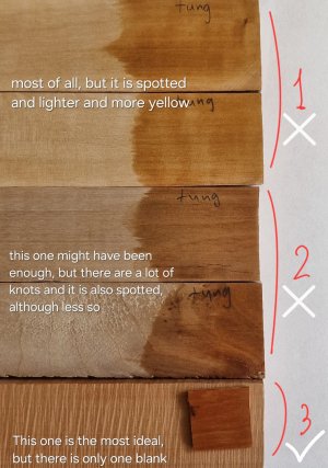
Only the third color pleased me, but I have only one plate and such a color - it will be for things on the deck and I was looking for material on the deck and sides.
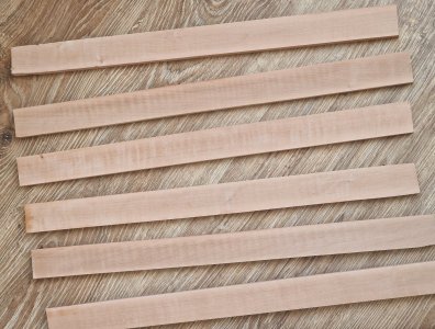
The photo above shows transverse stripes that appear under oils (any) like this:
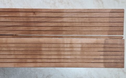
Even bitumen does not save from this banding and spotting. Although the color is just wonderful under bitumen, I checked, it behaves the same on the spots, even through it the spots and stripes are visible. And it turns out that I have all the wood either in knots and with a pronounced structure, or in stripes and spots...
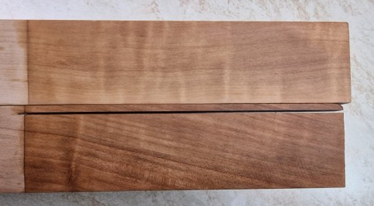
BUT... there is one but... And that's good news.
The person who sold me the Alert set and agreed to me to cut my pears advised me to find a person from whom I bought myself a pear even before the war. He did not remember where, and no matter how I searched the Internet, I could not find this seller. And when I was already desperate and flipping through everything on OLX (local eBay), I accidentally found a pink pear seller who has been selling it for modellers for 15 years. I called him and on Friday I will order 40 50x5000 dies of different thickness of a pink pear of several tones. And since eminent modellers bought from him and he has been doing this for many years, I hope that it will be the perfect pear.
To be honest - it already added motivation... because the last days only about the pear and thought and little engaged in the ship.
So moreover, he is still engaged in 3D milling and in theory, with him I can make a ship hull for the second Alert... and this is another pain that I had before recently, after the person who could help me with this was taken to war.
So, let's hope for the best and that everything will work out as planned.
And won about wood. In short, I have a supply of pears in basically two tones (darker and lighter). And I thought to use it on the second case of Alert. And a couple of days ago I got it to plan to cut into blanks, and there is trouble!! The one that is darker - it is all in knots and it will not be enough for everything in such a condition (there will be a lot of marriage). And the one that is lighter (not only is it a little with a yellow tint, but you want it with brown), but it is also striped and spotty. Like the one that is darker, but it is not so much spotted. In short, this all upset me very much and for a couple of days I was confused. I spent 2 days calculating the material that I have, but I understood that it would suck.

Only the third color pleased me, but I have only one plate and such a color - it will be for things on the deck and I was looking for material on the deck and sides.

The photo above shows transverse stripes that appear under oils (any) like this:

Even bitumen does not save from this banding and spotting. Although the color is just wonderful under bitumen, I checked, it behaves the same on the spots, even through it the spots and stripes are visible. And it turns out that I have all the wood either in knots and with a pronounced structure, or in stripes and spots...

BUT... there is one but... And that's good news.
The person who sold me the Alert set and agreed to me to cut my pears advised me to find a person from whom I bought myself a pear even before the war. He did not remember where, and no matter how I searched the Internet, I could not find this seller. And when I was already desperate and flipping through everything on OLX (local eBay), I accidentally found a pink pear seller who has been selling it for modellers for 15 years. I called him and on Friday I will order 40 50x5000 dies of different thickness of a pink pear of several tones. And since eminent modellers bought from him and he has been doing this for many years, I hope that it will be the perfect pear.
To be honest - it already added motivation... because the last days only about the pear and thought and little engaged in the ship.
So moreover, he is still engaged in 3D milling and in theory, with him I can make a ship hull for the second Alert... and this is another pain that I had before recently, after the person who could help me with this was taken to war.
So, let's hope for the best and that everything will work out as planned.

Good morning Sergey. Wow. After reading your work on your keel, grinding line etc there is much I missed out on. There are one or two things I can improve on when I take it out the cradle so thanks for sharing your detail. You have skills for sure. Cheers Grant
Thank you very much. Yes, I try to think everything through as much as possible in advance. It takes a lot of time and it is not always possible to think everything through, but if you do everything as timely as possible and take into account future manipulations, then this will simplify future steps or even make them possible, since sometimes if something is not done on time, then it is not always possible to fix it. Now I am just thinking about one global change and deciding whether to do it... but this is a little later)))Good morning Sergey. Wow. After reading your work on your keel, grinding line etc there is much I missed out on. There are one or two things I can improve on when I take it out the cradle so thanks for sharing your detail. You have skills for sure. Cheers Grant
Thanks a lot.Nicely made details and explanations, Sergey.
Regards, Peter
2.6 Lodgements for front and rear frames.
Finally, the final part of this chapter... several parts and you can collect everything in one lump.
As I mentioned earlier, I will redo the rear lodgements, since those from the set are light.
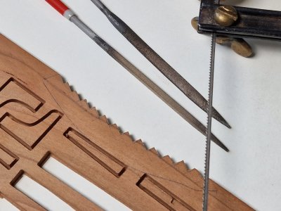
The plus is that although there are not many on the dies, there is an empty space where you can place the parts. Cut out with a hand jigsaw and refined with files.
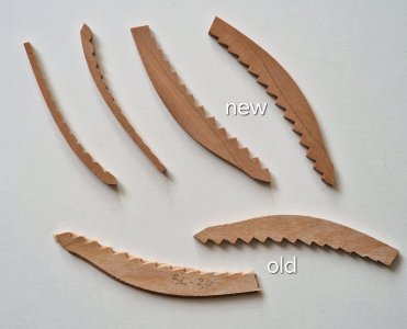
The photo is not very visible, but in life the old ones are much lighter and grainy and I do not regret the time spent on processing new ones.
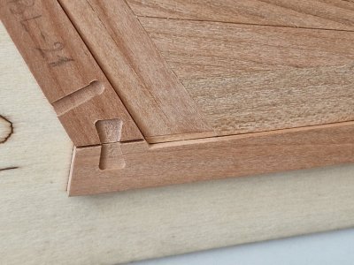
I did the processing with a grinder, but I'll warn you right away... for beginners, I recommend that you definitely practice on the probe, since the manipulation is quite difficult.
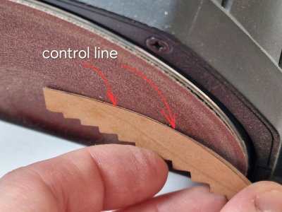
It is imperative to set reference lines to see the edges of the parts. Well, here is the result before and after grinding.
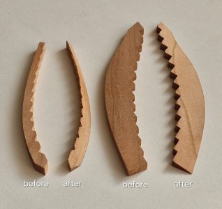
Well, it is not unimportant, symmetry and repeatability, since the sides are mirrored and the parts should be the same.
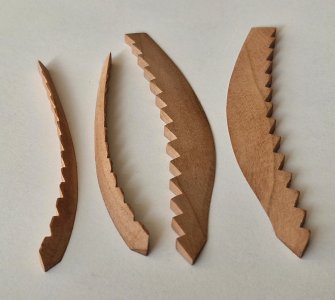
Naturally, the parts are pre-processed and after fixation, they will be ground in place together with the frames. But now I will not fix them. During the assembly process, I will once again adjust everything to each other and adjustments can be made.
I also prepared the details of the BL30.
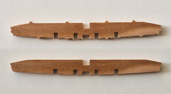
Cut off the holders and sanded it, but again, I did not contour it like 3 pairs of front frames. There are special stickers for all these parts, but! I do not recommend blindly believing in the accuracy of all these stickers. It is better to do all these manipulations in place during the assembly process so as not to polish too much.
And the last detail was a temporary keel. Its purpose is to replace the real keel at the time of assembly of the case. And after the final grinding of the case (and most likely during the grinding process), it will be removed and the case will be scanned. All this will be necessary so that the hull bulb for the second model is without a keel. And the keel will be made and glued at the time of lining with slats. On this body from the set, a real keel will be installed after the external surfaces of the model are scanned and finally polished. If nothing is clear, then in the future I will talk about it in detail.
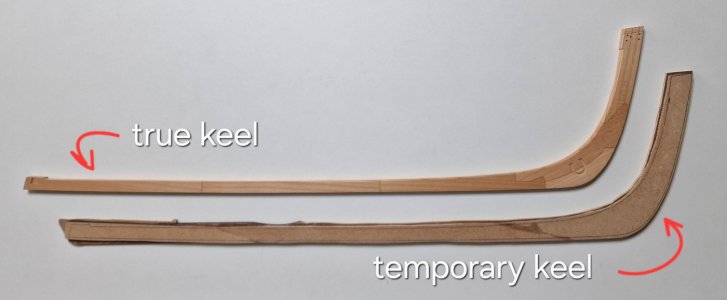
The temporary keel was made from fragments of templates (jig) on which there were frames. I glued suitable pieces together with diagonal joints and two layers with just a little grinding gave exactly the same thickness as the keel. In the next chapter, I will show in detail and tell you about this detail...
... in the meantime, we can officially say that chapter 2 is over!
P.S. and finally it will be possible to show the slipway, which is already ready for me and is waiting for publication.

Finally, the final part of this chapter... several parts and you can collect everything in one lump.
As I mentioned earlier, I will redo the rear lodgements, since those from the set are light.

The plus is that although there are not many on the dies, there is an empty space where you can place the parts. Cut out with a hand jigsaw and refined with files.

The photo is not very visible, but in life the old ones are much lighter and grainy and I do not regret the time spent on processing new ones.
I did the processing with a grinder, but I'll warn you right away... for beginners, I recommend that you definitely practice on the probe, since the manipulation is quite difficult.

It is imperative to set reference lines to see the edges of the parts. Well, here is the result before and after grinding.

Well, it is not unimportant, symmetry and repeatability, since the sides are mirrored and the parts should be the same.

Naturally, the parts are pre-processed and after fixation, they will be ground in place together with the frames. But now I will not fix them. During the assembly process, I will once again adjust everything to each other and adjustments can be made.
I also prepared the details of the BL30.

Cut off the holders and sanded it, but again, I did not contour it like 3 pairs of front frames. There are special stickers for all these parts, but! I do not recommend blindly believing in the accuracy of all these stickers. It is better to do all these manipulations in place during the assembly process so as not to polish too much.
And the last detail was a temporary keel. Its purpose is to replace the real keel at the time of assembly of the case. And after the final grinding of the case (and most likely during the grinding process), it will be removed and the case will be scanned. All this will be necessary so that the hull bulb for the second model is without a keel. And the keel will be made and glued at the time of lining with slats. On this body from the set, a real keel will be installed after the external surfaces of the model are scanned and finally polished. If nothing is clear, then in the future I will talk about it in detail.

The temporary keel was made from fragments of templates (jig) on which there were frames. I glued suitable pieces together with diagonal joints and two layers with just a little grinding gave exactly the same thickness as the keel. In the next chapter, I will show in detail and tell you about this detail...
... in the meantime, we can officially say that chapter 2 is over!
P.S. and finally it will be possible to show the slipway, which is already ready for me and is waiting for publication.

- Joined
- Mar 1, 2022
- Messages
- 692
- Points
- 308

Great achivement!2.6 Lodgements for front and rear frames.
Finally, the final part of this chapter... several parts and you can collect everything in one lump.
As I mentioned earlier, I will redo the rear lodgements, since those from the set are light.
View attachment 516428
The plus is that although there are not many on the dies, there is an empty space where you can place the parts. Cut out with a hand jigsaw and refined with files.
View attachment 516429
The photo is not very visible, but in life the old ones are much lighter and grainy and I do not regret the time spent on processing new ones.
I did the processing with a grinder, but I'll warn you right away... for beginners, I recommend that you definitely practice on the probe, since the manipulation is quite difficult.
View attachment 516430
It is imperative to set reference lines to see the edges of the parts. Well, here is the result before and after grinding.
View attachment 516431
Well, it is not unimportant, symmetry and repeatability, since the sides are mirrored and the parts should be the same.
View attachment 516432
Naturally, the parts are pre-processed and after fixation, they will be ground in place together with the frames. But now I will not fix them. During the assembly process, I will once again adjust everything to each other and adjustments can be made.
I also prepared the details of the BL30.
View attachment 516433
Cut off the holders and sanded it, but again, I did not contour it like 3 pairs of front frames. There are special stickers for all these parts, but! I do not recommend blindly believing in the accuracy of all these stickers. It is better to do all these manipulations in place during the assembly process so as not to polish too much.
And the last detail was a temporary keel. Its purpose is to replace the real keel at the time of assembly of the case. And after the final grinding of the case (and most likely during the grinding process), it will be removed and the case will be scanned. All this will be necessary so that the hull bulb for the second model is without a keel. And the keel will be made and glued at the time of lining with slats. On this body from the set, a real keel will be installed after the external surfaces of the model are scanned and finally polished. If nothing is clear, then in the future I will talk about it in detail.
View attachment 516434
The temporary keel was made from fragments of templates (jig) on which there were frames. I glued suitable pieces together with diagonal joints and two layers with just a little grinding gave exactly the same thickness as the keel. In the next chapter, I will show in detail and tell you about this detail...
... in the meantime, we can officially say that chapter 2 is over!
P.S. and finally it will be possible to show the slipway, which is already ready for me and is waiting for publication.
Chapter 3. Carcass Assembly
The chapter will consist of several parts:
3.1 slipway (gluing jigs to assemble the case),
3.2 keel (rework and gluing of keel),
3.3 stern I (gluing the rear of the ship),
3.4 front frames (adjustment and fixation of frames),
3.5 stern II (continued work on the rear part),
3.6 rear frames,
3.7 middle frames.
3.1 Assembly of the Slipway.
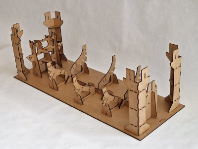
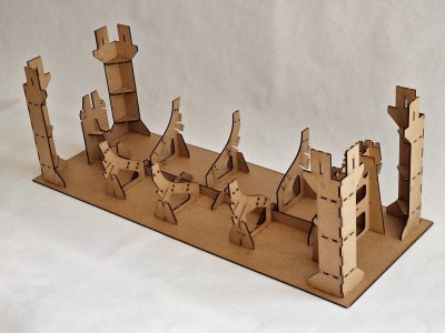
I didn't think this stage would be so fast... I collected the slipway in one day. And in one more day he was completely glued together... and it was cool.
To watch something unreal come out of 4.5 plates - it was so exciting. Something has not fascinated me for a long time... but in order. (I did not forget to take pictures of everything and I think my illustrations will help those who will collect this cool kit.
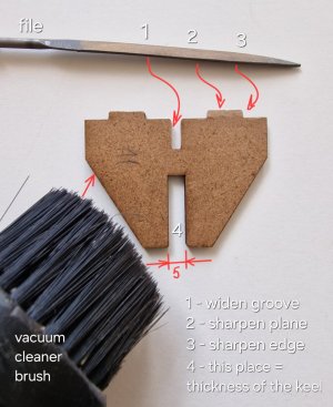
And I'll start right away with a few tips:
I. In order not to breathe dust from burning when laser cutting - use a vacuum cleaner with such a nozzle. she does a good job of cleaning up what then flies in the air.
II. In order for the parts to be better assembled, use a file. And as shown in the photo above: 1- slightly expand the grooves into which the parts will enter (but not much). 2- sharpen the plane that will enter the groove (but again not much, check and then you will understand how much you need to grind), 3- sharpen a little the ends so that the parts do not wedge, 4- the groove for the keel should be the same size as the keel + - 5 mm. This must be done before gluing, otherwise it will then be inconvenient to grind in place.
III. I recommend that you first assemble the entire slipway and only then glue it. And remember that there are parts that need to be fixed NOT using glue!!!
Next, we go according to the instructions...
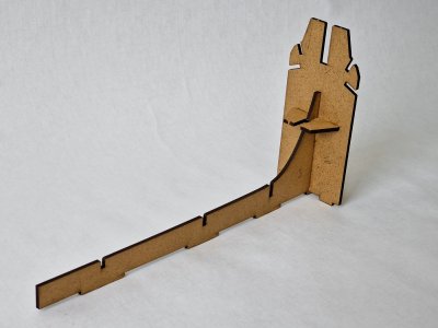
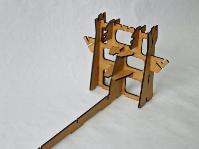
Next, we will analyze a little detail of the amplification for the front and rear structures.
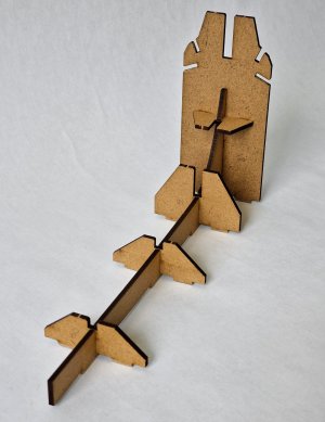
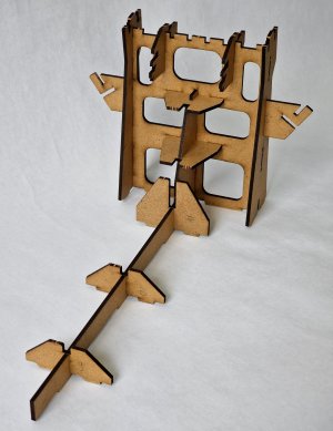
I repeat, the grooves for the keel should be thick so that the keel of the tad passes tightly, does not wedge and does not dangle. This needs to be checked before gluing.
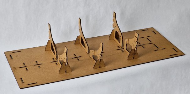
Special attention to these side holders. Front and back with identical gluing slots, and they need not to be confused!
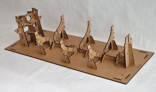
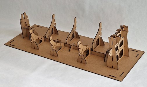
But these columns have their own sides!
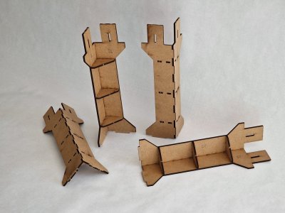
Parts 28 and 29 are not the same, so you need to strictly follow the instructions and before gluing - try to put the cover on top to make sure that it passes into your grooves!
I also advise you to slightly expand the slot for the following parts, otherwise, when you spell, the parts may be damaged.

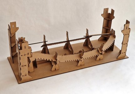
The photo below shows the parts that are fixed WITHOUT glue!
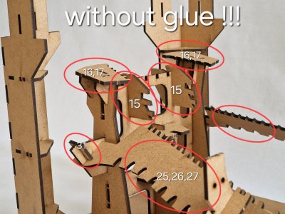
Details 25,26,27 can be unfastened, and 16,17. And when pulling out the case with the upper cover, the parts 15 will be removed together with the case. If they are glued, they will simply jam the case and have to destroy the slipway.
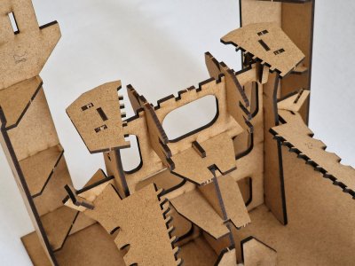
Glued the entire slipway to gel cyanocrylate with an activator. It is possible on PVA, but then it will be necessary to wait a little and hold all the parts together for a long time. CA - allows you to quickly and efficiently glue (necessarily gel) if you use an activator.
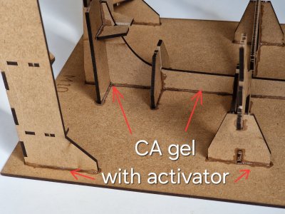
I glued everything right at the very end, so all the photos below (like all the upper ones) will also be without glue.
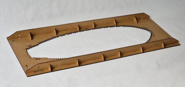
To connect the bottom with the lid, you need to use shutters, without glue!

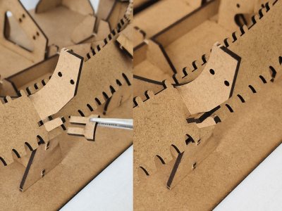
And toothed parts are also fixed with special latches, and also without glue.
I do not advise you to paint the slipway. I wanted to... but this idea is not very good. The material is poorly painted with aerosol paint. And all this I wanted in order to block the zone of blackness from laser cutting. It will contact the side surfaces of the frames and can paint them. So far I have polished these places with a small file. It doesn't seem to get dirty. But you can try to cover these zones with varnish (I haven't tried it yet), but if after testing from a file the result is 100%, then this will be the right way.
This completes the assembly and in the next post I will show photos of the finished slipway (note: in the photo, the slipway has so far been assembled without glue.)
Last edited:
Since I am a very practical and provident person, I understood that the slipway for the entire assembly period would stand and fall with dust most of the time... therefore, I bought a suitable cardboard box and will hide the slipway in it.

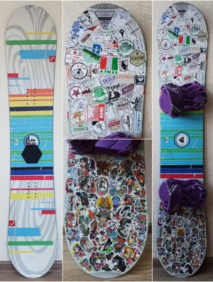
I pasted tape over it to increase wear resistance, but the look by the box is boring to say the least. And then I remembered that I had a mountain of vinyl stickers left and now they have a use. (Once, many years ago, I bought them for pasting our stowbords with my wife. I quickly did not find my photo, but I will show my wife, and you will understand that I have more than enough stickers)
And since I am a big fan of superhero films, I decided to paste the box with them. Marvel and DS are one love
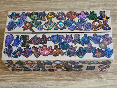
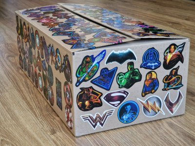
And now when I approach the ship to start building it - I'm doubly happy.


I pasted tape over it to increase wear resistance, but the look by the box is boring to say the least. And then I remembered that I had a mountain of vinyl stickers left and now they have a use. (Once, many years ago, I bought them for pasting our stowbords with my wife. I quickly did not find my photo, but I will show my wife, and you will understand that I have more than enough stickers)


And since I am a big fan of superhero films, I decided to paste the box with them. Marvel and DS are one love


And now when I approach the ship to start building it - I'm doubly happy.

3.2 Keel (rework and gluing of vertical stabilizer)
Before gluing frames and other parts to the keel, you need to fit everything in place. But to begin with, I glued a false keel with a temporary one.
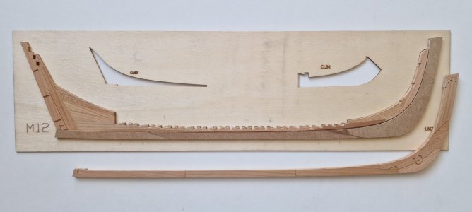
Let me remind you why I did it. Firstly, then it will be easier to grind the case when the keel and sternpost do not interfere (by the way, I will not glue it, I will only temporarily fix it, but it will be removed during grinding). And secondly, I want to scan the hull after the final grinding and then create the basis for the second hull using this scan and then cover it with skin, lay the deck and sides. And only after that glue the keel to this body.
The temporary keel was glued to the clerical PVA, pointwise. And then, when heated, the temporary keel can be peeled off and peeled off the rest of the glue, and then glued after the already permanent one.
The next step will be to create a horizontal stern base.
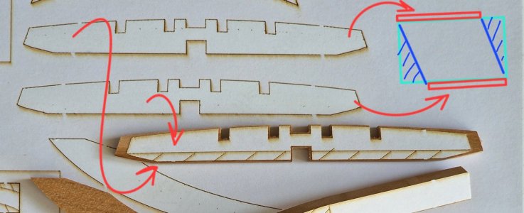
To do this, there are two stickers and by placing them at the top and bottom, you can create the correct part profile.
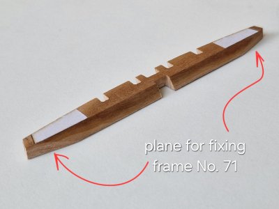
You also need to create planes for the 71st frame. It is better to do this not immediately, but by trying on and grinding gradually.
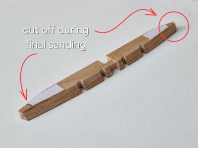
And the edges can not be cut at all and cut at the moment of final grinding, so as not to grind too much.
To speed up the process, you can grind the part either with an engraver...
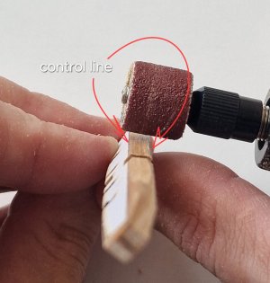
... trying not to go beyond the control lines. Or on an angle grinder, as I did. But it is more difficult and you can polish too much.
After that, I secured this part and placed the keel in the slipway, while without glue. Then, on the clothespins, he fixed lodgements for the rear frames to check their correct shape and position.
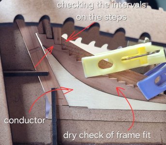
And until all these parts are glued, you can check whether the interval between the frames, the height and their inclination are correct.
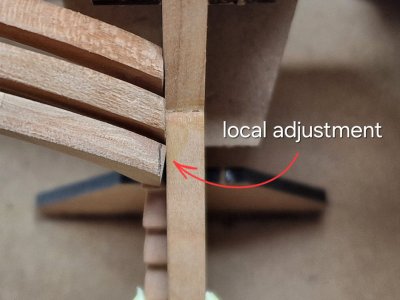
Naturally, each frame needs to be adjusted to its place. And when everything sits perfectly dry, you can go further.
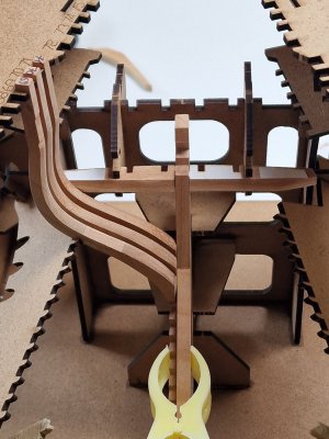
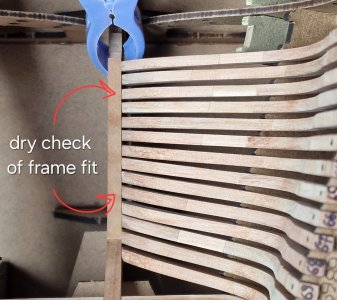
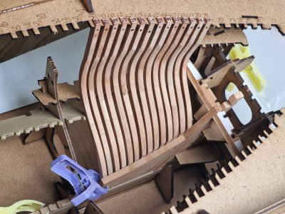
The final adjustments will be at the moment of gluing.
And by the way about gluing. In order not to stain surfaces with glue, which will no longer be ground, they can be covered with tape.
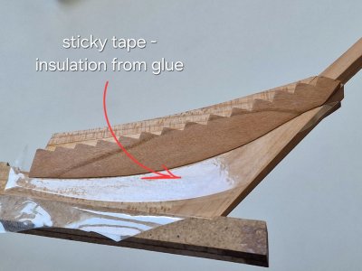
The disadvantage of PVA is that if it is not removed on time, it can imperceptibly remain a film and then the coating oil can unevenly impregnate the tree and there will be a stain in this place. In theory, this place can be erased immediately, but then it must be polished, since PVA will still seal the pores of the tree and can also distort the color after oil.
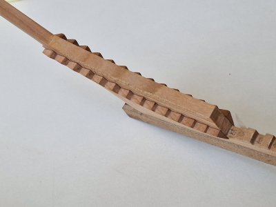
The next stage will not be quite according to the instructions, the result, I think, will be better...

Before gluing frames and other parts to the keel, you need to fit everything in place. But to begin with, I glued a false keel with a temporary one.

Let me remind you why I did it. Firstly, then it will be easier to grind the case when the keel and sternpost do not interfere (by the way, I will not glue it, I will only temporarily fix it, but it will be removed during grinding). And secondly, I want to scan the hull after the final grinding and then create the basis for the second hull using this scan and then cover it with skin, lay the deck and sides. And only after that glue the keel to this body.
The temporary keel was glued to the clerical PVA, pointwise. And then, when heated, the temporary keel can be peeled off and peeled off the rest of the glue, and then glued after the already permanent one.
The next step will be to create a horizontal stern base.

To do this, there are two stickers and by placing them at the top and bottom, you can create the correct part profile.

You also need to create planes for the 71st frame. It is better to do this not immediately, but by trying on and grinding gradually.

And the edges can not be cut at all and cut at the moment of final grinding, so as not to grind too much.
To speed up the process, you can grind the part either with an engraver...

... trying not to go beyond the control lines. Or on an angle grinder, as I did. But it is more difficult and you can polish too much.
After that, I secured this part and placed the keel in the slipway, while without glue. Then, on the clothespins, he fixed lodgements for the rear frames to check their correct shape and position.

And until all these parts are glued, you can check whether the interval between the frames, the height and their inclination are correct.

Naturally, each frame needs to be adjusted to its place. And when everything sits perfectly dry, you can go further.


The final adjustments will be at the moment of gluing.
And by the way about gluing. In order not to stain surfaces with glue, which will no longer be ground, they can be covered with tape.

The disadvantage of PVA is that if it is not removed on time, it can imperceptibly remain a film and then the coating oil can unevenly impregnate the tree and there will be a stain in this place. In theory, this place can be erased immediately, but then it must be polished, since PVA will still seal the pores of the tree and can also distort the color after oil.

The next stage will not be quite according to the instructions, the result, I think, will be better...

3.3 Stern I (gluing the rear of the ship).
A little lyric...
Before buying this set, I looked through all the forum branches on this ship. Not all unfortunately buildings were completed and many reviews were more likely interval photo reports. Repeatedly I rewatched the branches of the buildings of these users: @stan167 , @glennb17 , @PeterM , @Keef , @shota70 . Thank you for sharing your experience! But special thanks for the very detailed instructions for the construction, I want to say @Jimsky and @Maarten , reviews of which were similar to a photo instruction. (hopefully Jimsky will finish his model). And why am I saying this... that I, when I was interested in this information, received it here. And in gratitude, I try to create my review in even more detail and with a lot of information, advice and recommendations. On the experience of pioneers, I try to use their experience and not repeat mistakes. They were much harder and forgiven any mistakes. And having studied the instruction and all the reviews of buildings, I go my own way. And as you noticed, this path is not always according to the instructions. But I argue in every case why I did there or otherwise. Plus, in addition, I also plan to simultaneously make two buildings after a certain stage. Therefore, my review is also designed for those who want, who so want not to be limited to the result out of the box, but to go further... up to sails. I hope I go this way to the end.
P.S. I also wanted to note very good work on the body of the user Roly, and of course Dali, which worked very well not only on the body and skin of the ship, but also on the mast and rigging.
P.P.S. Also, I wanted to thank everyone again for your interest and positive reviews and likes. This is motivating, as it makes it clear that someone is useful and interested. Thank you friends!
So, with the finalization of the keel and the gluing of the slipway, I will finally begin to connect all this. And we will start with the stern.
And here the first significant departure from the instruction begins. The rear plane under the stern, according to the instructions, should be done after all the work on the sides, and this is strange, since then there will be limited access to it due to the glued stern and the hull will have to be polished again. What I propose to do... make this zone first.
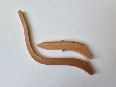
On the last frame, you need to profile the half-frame, as will be seen in the photo. It is a pity that for some reason they are shorter than necessary. I had to add a little, since there was no longer an empty meta on the dies.
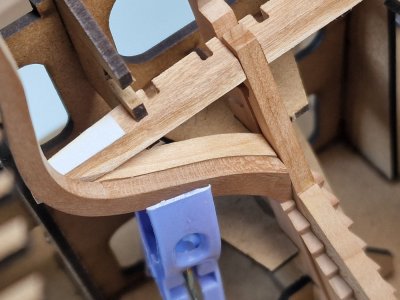
It is necessary to immediately grind the zone from the inside and sweat on the frame, since then there will be no good access to them.
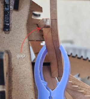
Then I glued the last frame (71) to the keel, but did not fix it to the slipway!
Glued to different adhesives depending on needs. Where sleep needed time for correction used PVA. And where you needed speed - there is a gel cyanocrin.

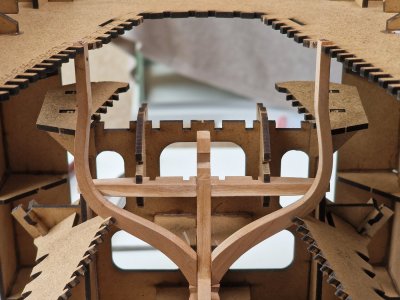
Similarly, the penultimate frame (70) was glued.
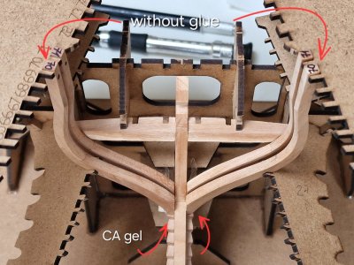
Then I connected these two frames to each other with a temporary jumper so that when the keel was removed from the slipway, they were stronger.
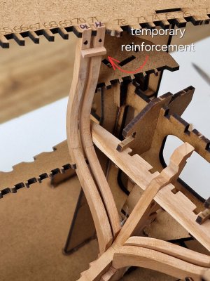
And now it was possible to remove the top cover...
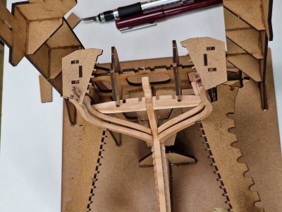
... safely pull out the keel.
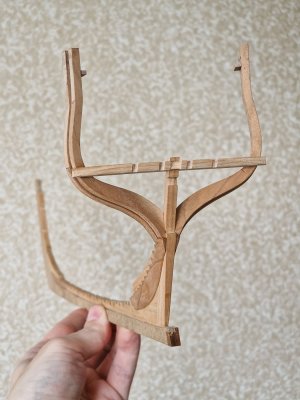
Then, I profiled the half-frames and tried them on in place.
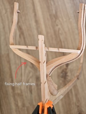
Here are the inserts I mentioned earlier. I really hope that they will not be striking.
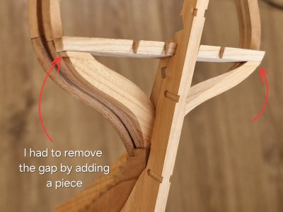
Well, then, again not according to the instructions, I cut two horizontal parts.
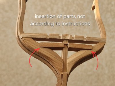
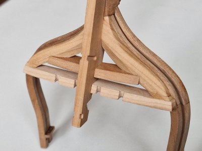
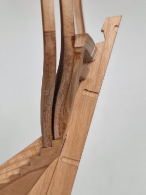
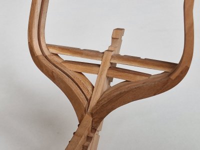
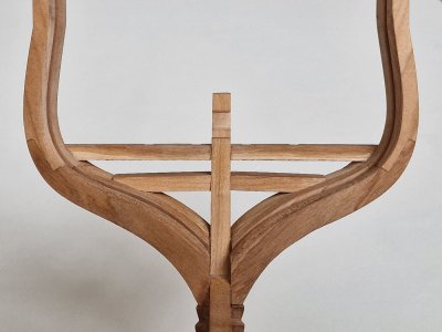
And together with the half-hangers, he glued it all in place. The implementation that the manufacturer offered is not correct. According to the drawings, there is not close to what is in the instructions for the set. I did closer to the truth. Although not tangentially, the connection was made by cutting in, which was often found on ships and was stronger in functionality. And visually I really liked this decision.
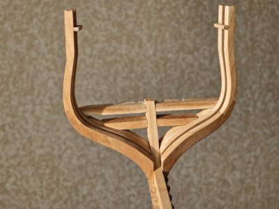
But the main aspect in all this is that in my case there is very good access to grinding this knot and the ability to give it the right shape.
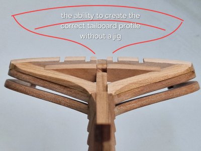
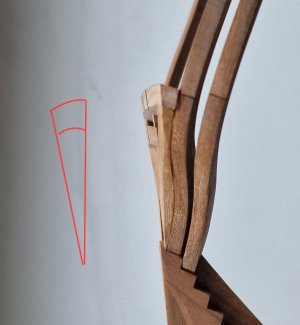
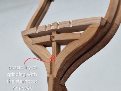
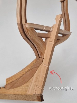
All outer contours and seams will be ground at the end, but the result is already visualized.

A little lyric...
Before buying this set, I looked through all the forum branches on this ship. Not all unfortunately buildings were completed and many reviews were more likely interval photo reports. Repeatedly I rewatched the branches of the buildings of these users: @stan167 , @glennb17 , @PeterM , @Keef , @shota70 . Thank you for sharing your experience! But special thanks for the very detailed instructions for the construction, I want to say @Jimsky and @Maarten , reviews of which were similar to a photo instruction. (hopefully Jimsky will finish his model). And why am I saying this... that I, when I was interested in this information, received it here. And in gratitude, I try to create my review in even more detail and with a lot of information, advice and recommendations. On the experience of pioneers, I try to use their experience and not repeat mistakes. They were much harder and forgiven any mistakes. And having studied the instruction and all the reviews of buildings, I go my own way. And as you noticed, this path is not always according to the instructions. But I argue in every case why I did there or otherwise. Plus, in addition, I also plan to simultaneously make two buildings after a certain stage. Therefore, my review is also designed for those who want, who so want not to be limited to the result out of the box, but to go further... up to sails. I hope I go this way to the end.
P.S. I also wanted to note very good work on the body of the user Roly, and of course Dali, which worked very well not only on the body and skin of the ship, but also on the mast and rigging.
P.P.S. Also, I wanted to thank everyone again for your interest and positive reviews and likes. This is motivating, as it makes it clear that someone is useful and interested. Thank you friends!
So, with the finalization of the keel and the gluing of the slipway, I will finally begin to connect all this. And we will start with the stern.
And here the first significant departure from the instruction begins. The rear plane under the stern, according to the instructions, should be done after all the work on the sides, and this is strange, since then there will be limited access to it due to the glued stern and the hull will have to be polished again. What I propose to do... make this zone first.

On the last frame, you need to profile the half-frame, as will be seen in the photo. It is a pity that for some reason they are shorter than necessary. I had to add a little, since there was no longer an empty meta on the dies.

It is necessary to immediately grind the zone from the inside and sweat on the frame, since then there will be no good access to them.

Then I glued the last frame (71) to the keel, but did not fix it to the slipway!

Glued to different adhesives depending on needs. Where sleep needed time for correction used PVA. And where you needed speed - there is a gel cyanocrin.

Similarly, the penultimate frame (70) was glued.

Then I connected these two frames to each other with a temporary jumper so that when the keel was removed from the slipway, they were stronger.

And now it was possible to remove the top cover...

... safely pull out the keel.

Then, I profiled the half-frames and tried them on in place.

Here are the inserts I mentioned earlier. I really hope that they will not be striking.

Well, then, again not according to the instructions, I cut two horizontal parts.

And together with the half-hangers, he glued it all in place. The implementation that the manufacturer offered is not correct. According to the drawings, there is not close to what is in the instructions for the set. I did closer to the truth. Although not tangentially, the connection was made by cutting in, which was often found on ships and was stronger in functionality. And visually I really liked this decision.

But the main aspect in all this is that in my case there is very good access to grinding this knot and the ability to give it the right shape.


All outer contours and seams will be ground at the end, but the result is already visualized.


Under the stern, I finished, now you can prepare the details of the stern itself.
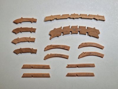
To begin with, you need to glue parts 37 in pairs, having prepared the surface as much as possible and squeezed as much as possible so that the glue seam is practically invisible, since logically it should be as one part.
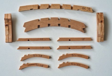
And while they stick together I prepared two other details. One slightly more complex shape. But according to special stickers, it is not difficult to make a uniform as before.
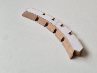
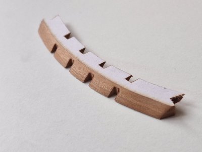
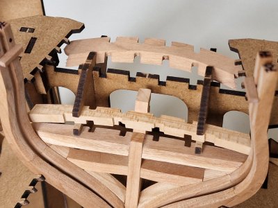
But you need to be careful with the corners, since the cherry tree is very fragile in fiber and you need to avoid chips. And here's the first fitting.
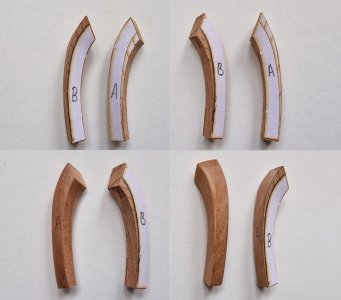
But with details 37 it turned out not so simple. And the difficulty is not in the implementation itself, but in the fact that the stickers in the set are not grouped correctly! I signed A and B so that it was clear from where which stickers and I would give detailed instructions on how to process these details.
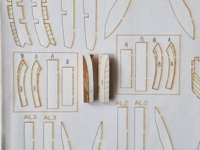
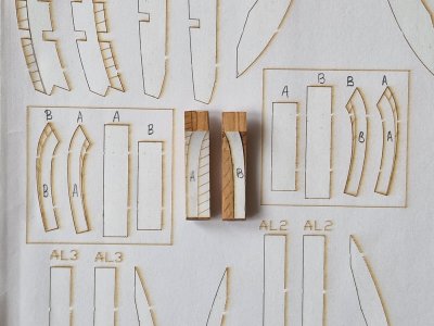
So, I processed them on a grinder and refined them with sandpaper with a cylindrical base.
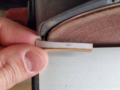
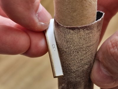
The most important thing is that you do not need to stick all 4 stickers at the same time. First you need to stick the top and bottom. Grind all unnecessary and only then stick two side and already grind other planes on them.
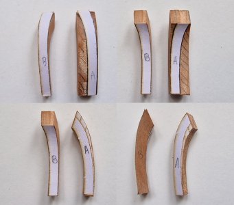
After that, you need to fit these parts as much as possible with the other two. So that the connection points are without gaps and steps.
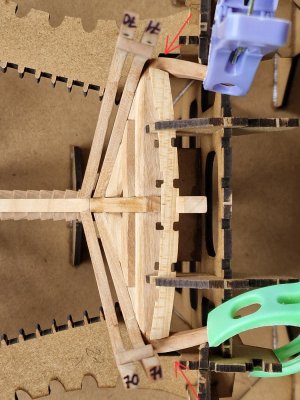
But the most difficult thing was to fit it without gaps.
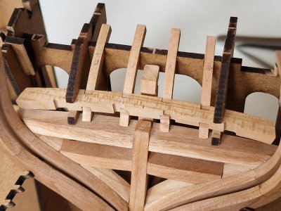
And the problem is not skills... these parts initially formed cracks, that is, they were small. But I came up with an implementation to eliminate all these gaps. Further in the review, I will tell you in detail about this.
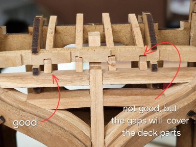
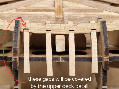
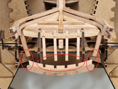
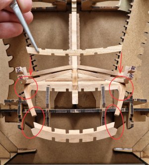
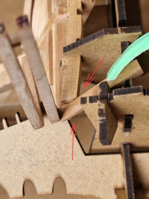
To properly fit some parts, you sometimes have to adjust the slipway.
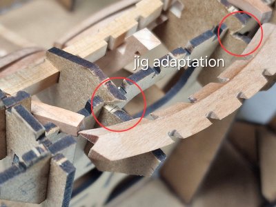
And after the final checks, I glued the side pieces (37) and the back, but I didn't glue the front piece.
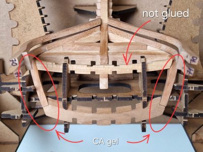
The frame was strong and it was possible to pull the keel out of the slipway again.
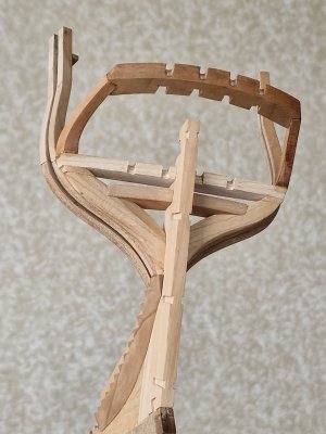
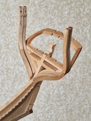
And in order to make it easier to get the model from the slipway in the future, I once again adjusted the details of the slipway.
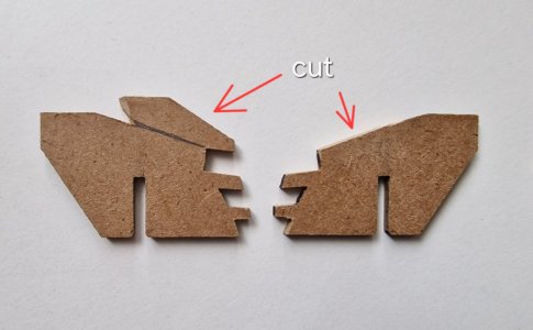
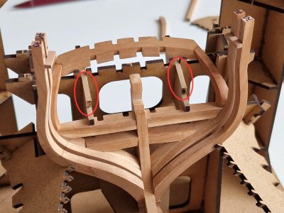
That's all for now, tomorrow there will be the 3rd part of the work on the stern. Good weekend everyone!

To begin with, you need to glue parts 37 in pairs, having prepared the surface as much as possible and squeezed as much as possible so that the glue seam is practically invisible, since logically it should be as one part.

And while they stick together I prepared two other details. One slightly more complex shape. But according to special stickers, it is not difficult to make a uniform as before.


But you need to be careful with the corners, since the cherry tree is very fragile in fiber and you need to avoid chips. And here's the first fitting.

But with details 37 it turned out not so simple. And the difficulty is not in the implementation itself, but in the fact that the stickers in the set are not grouped correctly! I signed A and B so that it was clear from where which stickers and I would give detailed instructions on how to process these details.


So, I processed them on a grinder and refined them with sandpaper with a cylindrical base.


The most important thing is that you do not need to stick all 4 stickers at the same time. First you need to stick the top and bottom. Grind all unnecessary and only then stick two side and already grind other planes on them.


After that, you need to fit these parts as much as possible with the other two. So that the connection points are without gaps and steps.


But the most difficult thing was to fit it without gaps.

And the problem is not skills... these parts initially formed cracks, that is, they were small. But I came up with an implementation to eliminate all these gaps. Further in the review, I will tell you in detail about this.


To properly fit some parts, you sometimes have to adjust the slipway.

And after the final checks, I glued the side pieces (37) and the back, but I didn't glue the front piece.

The frame was strong and it was possible to pull the keel out of the slipway again.


And in order to make it easier to get the model from the slipway in the future, I once again adjusted the details of the slipway.


That's all for now, tomorrow there will be the 3rd part of the work on the stern. Good weekend everyone!
Nicely done, Sergey! It is quite difficult to get everything properly in place on the stern. The jig seems very helpful!
Thank you. Yes, the frame is a good thing, but there are still many inconsistencies, unfortunately. Often you have to adjust 100500 times. Now I'm making the front part, and it's really difficult there. And I had to redo several parts. But it's still fun and brings pleasure))) And what else do you need from a hobby?Nicely done, Sergey! It is quite difficult to get everything properly in place on the stern. The jig seems very helpful!
Great work Sergey. You should copyright this log and sell it a an instruction manual….Under the stern, I finished, now you can prepare the details of the stern itself.
View attachment 518933
To begin with, you need to glue parts 37 in pairs, having prepared the surface as much as possible and squeezed as much as possible so that the glue seam is practically invisible, since logically it should be as one part.
View attachment 518934
And while they stick together I prepared two other details. One slightly more complex shape. But according to special stickers, it is not difficult to make a uniform as before.
View attachment 518935
View attachment 518937
But you need to be careful with the corners, since the cherry tree is very fragile in fiber and you need to avoid chips. And here's the first fitting.
View attachment 518938
But with details 37 it turned out not so simple. And the difficulty is not in the implementation itself, but in the fact that the stickers in the set are not grouped correctly! I signed A and B so that it was clear from where which stickers and I would give detailed instructions on how to process these details.
View attachment 518939
View attachment 518944
So, I processed them on a grinder and refined them with sandpaper with a cylindrical base.
View attachment 518945
View attachment 518946
The most important thing is that you do not need to stick all 4 stickers at the same time. First you need to stick the top and bottom. Grind all unnecessary and only then stick two side and already grind other planes on them.
View attachment 518947
View attachment 518948
After that, you need to fit these parts as much as possible with the other two. So that the connection points are without gaps and steps.
View attachment 518949
View attachment 518950
View attachment 518951
But the most difficult thing was to fit it without gaps.
View attachment 518952
And the problem is not skills... these parts initially formed cracks, that is, they were small. But I came up with an implementation to eliminate all these gaps. Further in the review, I will tell you in detail about this.
View attachment 518953
View attachment 518954
View attachment 518955
To properly fit some parts, you sometimes have to adjust the slipway.
View attachment 518956
And after the final checks, I glued the side pieces (37) and the back, but I didn't glue the front piece.
View attachment 518957
The frame was strong and it was possible to pull the keel out of the slipway again.
View attachment 518958
View attachment 518959
And in order to make it easier to get the model from the slipway in the future, I once again adjusted the details of the slipway.
View attachment 518960
View attachment 518961
That's all for now, tomorrow there will be the 3rd part of the work on the stern. Good weekend everyone!
 . Seriously tho it will be an amazing help to future Alert builders. Your wood work is so clean as well.
True story I have found this out the hard way alreadyBut you need to be careful with the corners, since the cherry tree is very fragile in fiber and you need to avoid chips.
Cheers Grant
Going back a couple weeks to post #142, I THINK the drawing is incorrect as the wales strake sticks out past the other planks. The wales had to sit in the rabbet same as the other planks so reduced in thickness at the bow. The model below is a contemporary model at Preble Hall but this can be seen on other contemporary models as well on contemporary planking expansion plans.
Allan
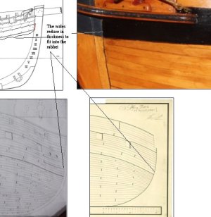
Allan

Last edited:


