• LUCZORAMA SHIPWRECK SCAVENGER HUNT GIVEAWAY. 4 Weeks of Fun • 1 Legendary Prize ((OcCre’s Fram Ship)) • Global Crew Welcome!
    **VIEW THREAD HERE**

HMS Alert [1777] 1:48 POF by serikoff. (Two hulls: skeleton and fully rigged)

Chapter 2. The Keel
The chapter will consist of several parts:

2.1 preparation (removal, removal of racks)
2.2 fitting, reworking of defects
2.3 first gluing (parts of false keel and parts of keel)
2.4 profiling, grinding and fitting of frames
2.5 rework (grooves, holes and XVIII)
2.6 lodgements for front and rear frames

2.1 подготовка (извлечение, устранение держателей)
2.2 подгонка, переделка брака
2.3 первая склейка (деталей ложного киля и отдельно деталей киля)
2.4 профилировка, шлифовка и подгонка шпангоутов
2.5 доработка (пазы, отверстия и XVIII)
2.6 ложементы для передних и задних шпангоутов.

... let's go!

2.1. Preparing the keel parts

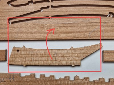
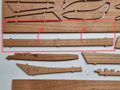
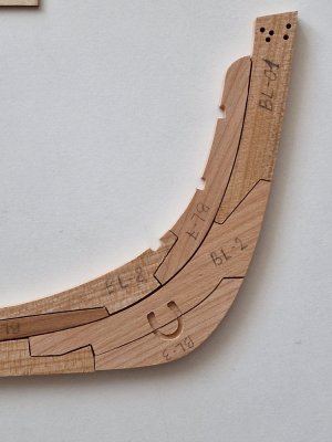
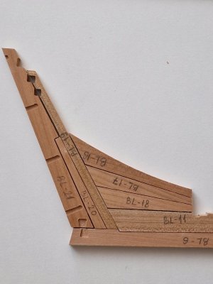
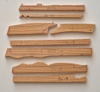
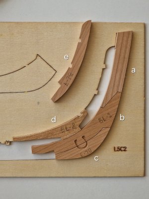
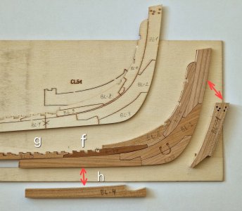
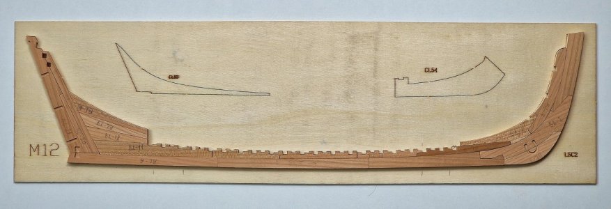
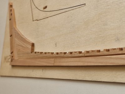
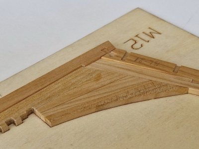
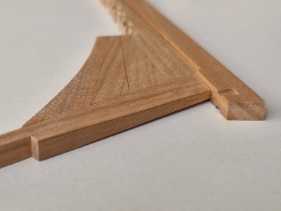
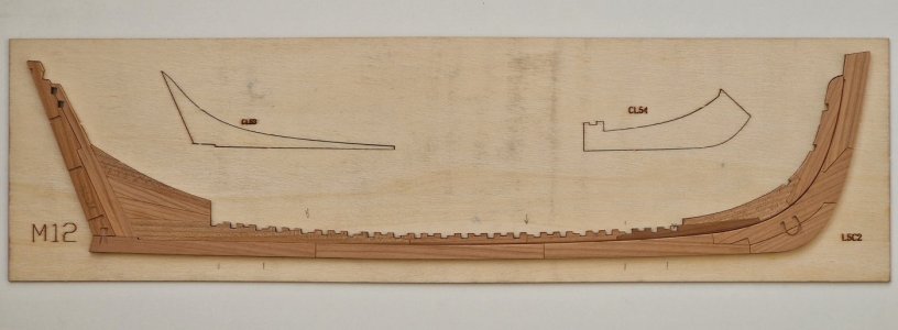
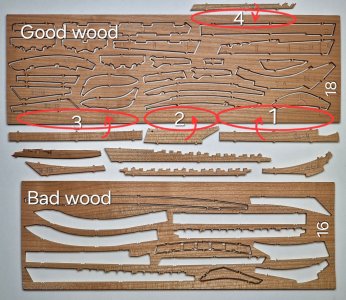
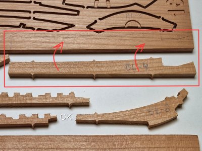
As I mentioned earlier, some keel parts are located on plate No.16, the wood of which has been cut in such a way that its grain and texture look very unattractive. So I decided to remake some of the parts using plate No.18, where there was a bit of unused space. I was very lucky that there was just enough room to fit all the necessary parts. Some pieces I won’t remake, since they will be either covered by the frames or hidden inside (marked with “OK”).
20250413_220217.jpg
20250413_220305.jpg
20250413_220448.jpg
20250413_220419.jpg

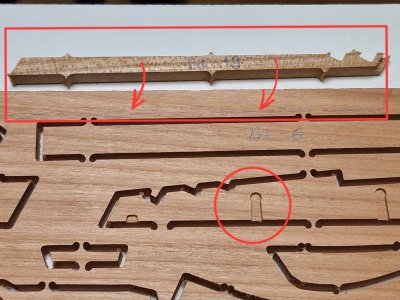
Another lucky moment: the parts I want to remake don’t contain any slots for metal components (like rudder hinges), as highlighted in the red circle.
20250413_220734.jpg

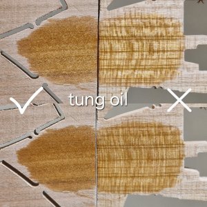
And for those who might find it old-fashioned or unnecessary to remake parts—and at first glance, the wood may seem identical—just take a look at the surface after applying tung oil…
20250413_220856.jpg

… I think this view justifies my decision, doesn’t it?
What do you think?

Also, I want to remake these light-colored parts using a darker brown wood… and I have a feeling this won’t be my last remake due to the light tone of the kit’s wood.
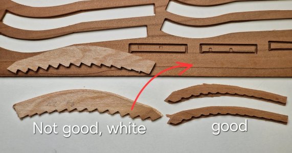
20250413_221416.jpg

I previously mentioned that I would make all keel parts from pearwood (via laser cutting). But this has been postponed for a month, and the second reason is that the pearwood will be much darker than the rest of the kit’s wood. So, I’ll make the keel from pearwood for the second hull, but for the main kit’s hull I’ll go with the plan described above. Seems more logical this way.

Let’s get started!

Ship-1
 
Last edited:
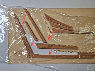
So, we continue...
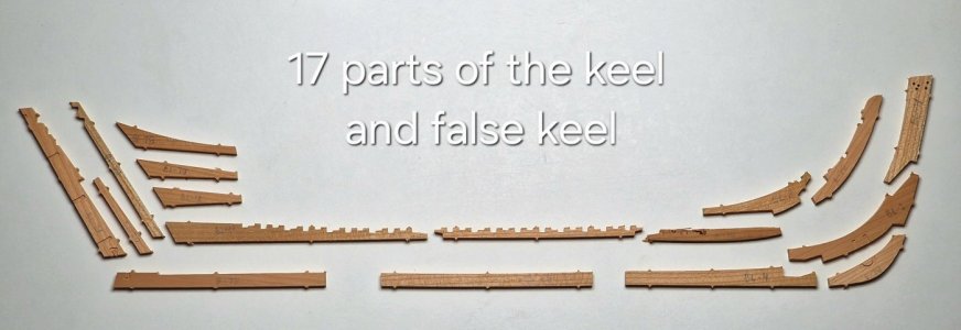
... all parts of the keel structure are removed from the dies and ready for processing.

Alert 198.jpg

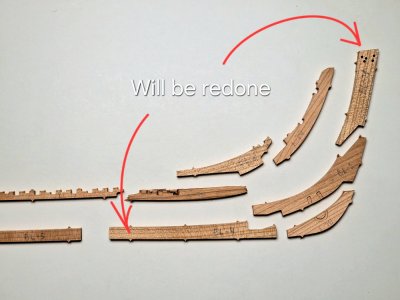
As I said before, I will redo 4 details.

Alert 199.jpg
Alert 200.jpg

I removed it from the raincoats with such a knife and polished the holders with a typewriter, but I have already talked about this in detail in the frames section, I will not repeat myself.

Alert 201.jpg

Also, he made all 90 ° angles with a file, since after the cutter they are rounded.

Alert 202.jpg

Dry put everything together and looked promising...

Alert 203.jpg
Alert 204.jpg

Now you need to remove the keel template from the jig and insert the keel parts into this jig to adjust them.

Alert 205.jpg
Alert 206.jpg

But first, I made the parts I wanted to replace.


2.2 Fitting and reworking of defects

Alert 207.jpg

Well, then I began to adjust the details to each other so that they could be easily inserted into the jig. As I understand it, it is better to immediately fit part 1, 2 and 3, then 8 and then only 7.

Alert 208.jpg

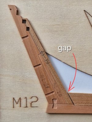
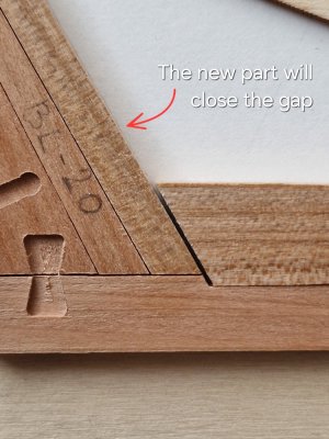
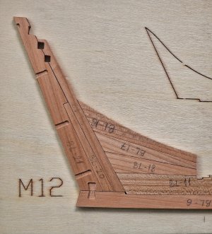
Then fit 9 and 10 and then 4. And here was the first moment. That the original part 4 was smaller and a gap was formed. And it's good that I began to redo it and performed it more to eliminate this gap.

Alert 209.jpg

P.S. soon to be continued.
 
So, we continue...
... all parts of the keel structure are removed from the dies and ready for processing.

View attachment 514055

As I said before, I will redo 4 details.

View attachment 514056
View attachment 514057

I removed it from the raincoats with such a knife and polished the holders with a typewriter, but I have already talked about this in detail in the frames section, I will not repeat myself.

View attachment 514058

Also, he made all 90 ° angles with a file, since after the cutter they are rounded.

View attachment 514059

Dry put everything together and looked promising...

View attachment 514060
View attachment 514061

Now you need to remove the keel template from the jig and insert the keel parts into this jig to adjust them.

View attachment 514062
View attachment 514063

But first, I made the parts I wanted to replace.


2.2 Fitting and reworking of defects

View attachment 514064

Well, then I began to adjust the details to each other so that they could be easily inserted into the jig. As I understand it, it is better to immediately fit part 1, 2 and 3, then 8 and then only 7.

View attachment 514065

Then fit 9 and 10 and then 4. And here was the first moment. That the original part 4 was smaller and a gap was formed. And it's good that I began to redo it and performed it more to eliminate this gap.

View attachment 514066

P.S. soon to be continued.
Hi serikoff, I wonder, are the parts you are working on structurally ready just to be cleaned and ground ? Frank
 
Hi serikoff, I wonder, are the parts you are working on structurally ready just to be cleaned and ground ? Frank
Hello. If you answer quickly, then yes. This is a kit in which all parts are cut out with a cutter. And it begins to finalize and grind them. If you are interested, then at the beginning of the branch I described in detail this kit and how I started to make it. Thank you for your interest.
 
Well, we continue.

A gap formed behind during assembly.

Alert 210.jpg
Alert 211.jpg

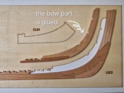
I compensated for it a little with a new part 19, but still a small point in the corner between parts 6, 11 and 19 remained. It will practically not be visible, so I think the new part 19 saved the situation.

Alert 212.jpg

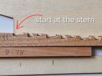
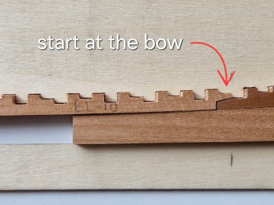
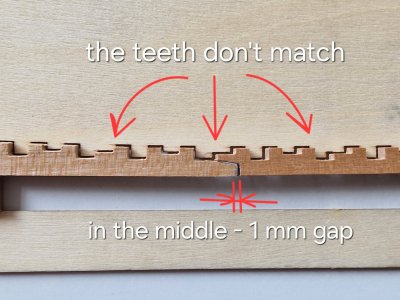
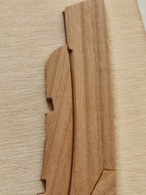
But the worst situation was in the middle part. Details 10 and 11 do not coincide with the jig (despite the fact that the jig itself coincides with the slipway, I checked). So I need to correct the details themselves.

Alert 213.jpg

That is, in fact, parts 10 and 11 coincide with the slipway only at one end.

Alert 214.jpg
Alert 215.jpg

But due to the fact that they are proportionally shorter by 0.5 mm (each) than necessary. And it would seem that this is not so much, but due to this, the scallops (teeth) to the end of the details do not coincide with the jig. And this difference runs up to 0.5 mm, which in total 1 mm gives the distance between parts 10 and 11.

Alert 216.jpg

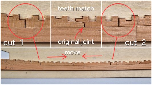
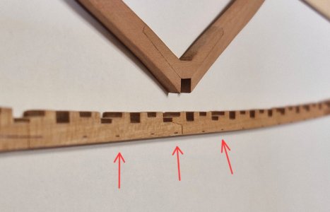
I do not want to redo such complex details (it is very long and difficult), because I will cut each of these details in the middle. And the middle ones will shift to each other. Thus, all 4 parts correctly become a jig. And the distance in the center will disappear, but two others will appear, which I will later show how I glued together.

Alert 217.jpg

This area will be covered by frames and profiled, therefore these joints will be visible minimally. Unfortunately, this is such a lamentable inconsistency, but I think everything will be fine. The main thing is that there is less of this further.

Strange, but I did not notice such problems in the sets that were collected here on the forum. Maybe this problem is only isolated (and I came across)) or this is a problem of those sets that are sold on AliExpress. Has anyone else encountered a similar problem of inconsistent teeth in parts 10 and 11? Or is it me lucky))

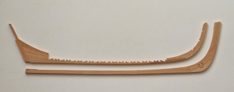
Well, now, all the details of the keel and false keel are clearly in place and ready for gluing.

Alert 218.jpg

The next stage of gluing the false keel... and spoiler - I already did it)) I'll show it soon too.
Thanks everyone for watching, glad you like it, have fun guys))

Ship-1
 
Last edited:
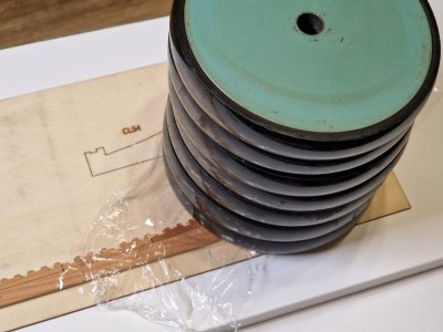
2.3 First gluing (parts of false keel and parts of keel).

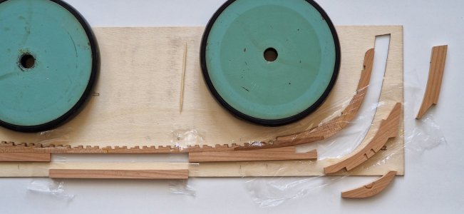
The gluing process is very similar to the gluing of frames. There is a template, and first you need to put in it those details that will not stick and cover everything with cling film. And then putting the parts in the right places, while not forgetting to add glue.

Alert 219.jpg

I indicated the logical order. Then everything is immobilized...

Alert 220.jpg

... and here is the finished result before grinding.

Alert 221.jpg
Alert 222.jpg

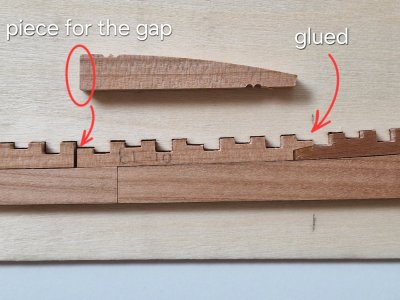
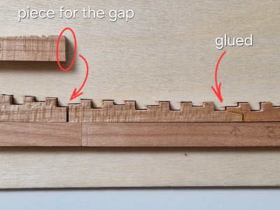
The middle part, if it were without defects, was glued together in places where it is indicated - gluing.

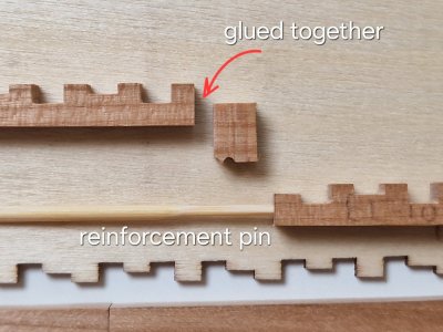
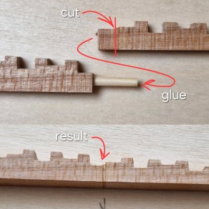
But, since I was fixing defective parts, I need to glue two more cuts.

Alert 223.jpg
Alert 224.jpg

To make it convenient to fix and process the fragment with which I will close the cracks - it is initially significantly larger than it should be.

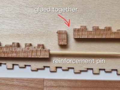
Well, for reliability - I strengthened the bonding point with a pin.

Alert 225.jpg
Alert 226.jpg

After fixing the pieces, I cut them to the right length and drilled a hole for the pin and glued the parts together.

Alert 227.jpg

Alert 228.jpg

And so I glued the false keel, now it's the turn of the true keel.

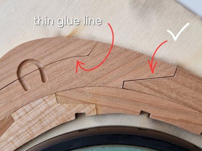
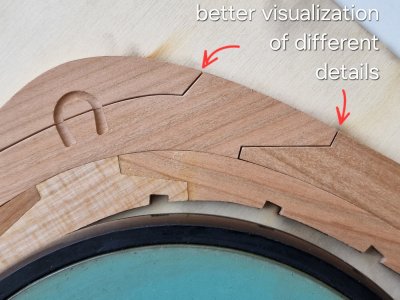
But there is one point. There is a different distance between all the parts, and the glue seam from this will also be different. Some glued to black PVA to highlight the seam and more visualize that the part consists of fragments and not monolithic. But if the seam is very thin, that is, the parts fit very well, then even a black PVA will be very invisible in a thin seam. Therefore, I made small chamfers at the edges and thus increased the thickness of the seam without sacrificing strength.

Alert 229.jpg

And here's the difference: (in the top photo - a thin seam, in the bottom photo - just as you need).

Alert 230.jpg

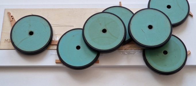
Well, then according to the old scheme: insulation with cling film...

Alert 231.jpg

... and fixation with a load and necessarily on a flat surface.

Alert 232.jpg

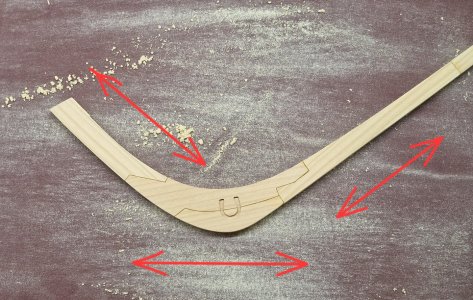
After the glue solidifies - grinding. All the same method. A sheet of sandpaper 240 is placed on a flat surface and the surface is flattened by such movements. 5.1 mm came out of 5.25 mm.

Alert 233.jpg

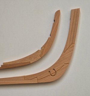
Well, almost ready-made result (only at the ends need to be polished).
I use Titebond II glue and it's yellow. Therefore, when the tree is covered with oil and it also turns a little yellow, the glue seam will look as harmonious as possible. It is enough to visualize the seams, but at the same time not to be very striking in dark tones.

Alert 235.jpg
Alert 234.jpg

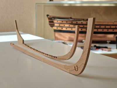
Well, here is the laid keel against the background of almost ready-made Victory... Soon I will take it... but about that in another thread...

Alert 236.jpg

P.S. so far I really like everything, but to be honest... it seemed to me that Alert would be larger... and he's so shallow. Probably everything after Victory will be small)))

Ship-1
 
2.3 First gluing (parts of false keel and parts of keel).

The gluing process is very similar to the gluing of frames. There is a template, and first you need to put in it those details that will not stick and cover everything with cling film. And then putting the parts in the right places, while not forgetting to add glue.

View attachment 514310

I indicated the logical order. Then everything is immobilized...

View attachment 514311

... and here is the finished result before grinding.

View attachment 514312
View attachment 514313

The middle part, if it were without defects, was glued together in places where it is indicated - gluing.

But, since I was fixing defective parts, I need to glue two more cuts.

View attachment 514314
View attachment 514315

To make it convenient to fix and process the fragment with which I will close the cracks - it is initially significantly larger than it should be.

Well, for reliability - I strengthened the bonding point with a pin.

View attachment 514316
View attachment 514317

After fixing the pieces, I cut them to the right length and drilled a hole for the pin and glued the parts together.

View attachment 514318

View attachment 514319

And so I glued the false keel, now it's the turn of the true keel.

But there is one point. There is a different distance between all the parts, and the glue seam from this will also be different. Some glued to black PVA to highlight the seam and more visualize that the part consists of fragments and not monolithic. But if the seam is very thin, that is, the parts fit very well, then even a black PVA will be very invisible in a thin seam. Therefore, I made small chamfers at the edges and thus increased the thickness of the seam without sacrificing strength.

View attachment 514320

And here's the difference: (in the top photo - a thin seam, in the bottom photo - just as you need).

View attachment 514321

Well, then according to the old scheme: insulation with cling film...

View attachment 514324

... and fixation with a load and necessarily on a flat surface.

View attachment 514325

After the glue solidifies - grinding. All the same method. A sheet of sandpaper 240 is placed on a flat surface and the surface is flattened by such movements. 5.1 mm came out of 5.25 mm.

View attachment 514326

Well, almost ready-made result (only at the ends need to be polished).
I use Titebond II glue and it's yellow. Therefore, when the tree is covered with oil and it also turns a little yellow, the glue seam will look as harmonious as possible. It is enough to visualize the seams, but at the same time not to be very striking in dark tones.

View attachment 514327
View attachment 514328

Well, here is the laid keel against the background of almost ready-made Victory... Soon I will take it... but about that in another thread...

View attachment 514331

P.S. so far I really like everything, but to be honest... it seemed to me that Alert would be larger... and he's so shallow. Probably everything after Victory will be small)))

Ship-1
This is very nice work, my friend! Excellent carpentry!

I thought you were going to replace a few of those parts???
 
This is very nice work, my friend! Excellent carpentry!

I thought you were going to replace a few of those parts???
Thanks for the praise. So I actually replaced some. But not all. Some will not be visible, so I left them, others (like scallops) are very complex, and it takes a long time to redo them. So I decided to fix them. But in the end, everything will be fine)) I hope..
 
Thanks for the praise. So I actually replaced some. But not all. Some will not be visible, so I left them, others (like scallops) are very complex, and it takes a long time to redo them. So I decided to fix them. But in the end, everything will be fine)) I hope..
Hi serikoff, to be appreciated for the quality of so much patience for such a challenging work but , Sorry , too many compromises do not make the quality of Your model. It is just my opinion that does not count with Your choices.Frank
 
Hi serikoff, to be appreciated for the quality of so much patience for such a challenging work but , Sorry , too many compromises do not make the quality of Your model. It is just my opinion that does not count with Your choices.Frank
Thank you, Frank. But I don’t think a couple of extra joints will have any real impact, especially since they won’t be visible. Part of the seam will be covered by the frames, and the rest will fall within the area to be faired. Fixing the parts only took a few minutes, while a full replacement would’ve taken several hours. I’ll show the result soon—I think it will be clear why this solution made more sense. It won’t affect the strength or the overall appearance. So no worries! The parts that really would’ve ruined the look—I’ve already replaced those.
 
But the worst situation was in the middle part. Details 10 and 11 do not coincide with the jig (despite the fact that the jig itself coincides with the slipway, I checked). So I need to correct the details themselves.
Hi Serikoff. Part BL11 is definitely a piece of crap (wood and scantling). A pity you didn't consider to saw it from a sound plank, instead or along with PL 19. Excellent recovery, btw.
 
Hi Serikoff. Part BL11 is definitely a piece of crap (wood and scantling). A pity you didn't consider to saw it from a sound plank, instead or along with PL 19. Excellent recovery, btw.
Definitely parts BL 9, 10 and 11 are complete crap, but I no longer had a donor for a part like BL11. And the difficulty in making all these teeth is not small. It would be right to remake these parts, but there is no suitable material and I decided not to bother. The fragments that will be visible will not be large, and I think they will not greatly affect the overall appearance, but it is definitely a pity that such material was in the set (( Thanks for the comment and rating.
 
Houston we have a problem...

This thread is called “building two hulls.” One hull is from the kit (the skeleton), and the second one was supposed to be made from pearwood, with fully planked sides and deck, and complete rigging and sails—that was the original idea.

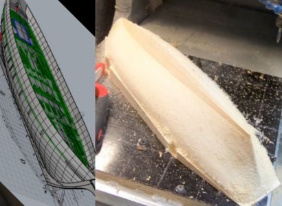
But today I found out that the person who had promised to help me, he was supposed to: 1) Laser cut the keel parts (and other elements); 2) 3D scan the completed skeleton of the kit hull; 3) Use the 3D model to CNC-mill a second hull from a single block, so I could then plank it, attach the pearwood keel, and install masts and sails… ... so, this man was taken to war!

Now, given the current situation, it’s safe to say this arrangement won’t happen. I truly hope he’ll be okay—but realistically, it could be months or even years before he’s available again. And so I have to start looking for alternatives. Otherwise, this “second hull” idea might never become a reality.
The problem is that now I’ll need to find three separate people or companies for each task, and that’s going to be expensive. For now, I still have plenty to do—the first hull is far from finished—but this news definitely hit my motivation hard…

P.S. I’ve made up my mind: I absolutely don’t want to plank the kit hull, not even partially. The masts, rigging, and planking will only go on the second hull, the one made entirely of pearwood. That’s the only way I envision this model. The kit wood—with all its color variations—is great for visualizing the skeleton, but not for a fully rigged ship. So I’ll keep looking for a way to bring my original plan to life… sigh

20250418_230852.jpg
 
Last edited:
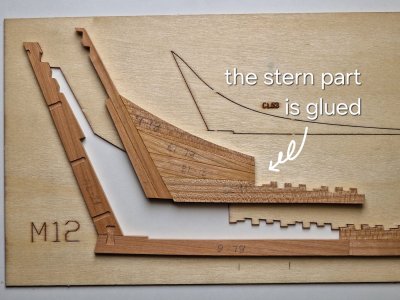
2.4 Profiling, grinding and fitting of frames.

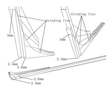
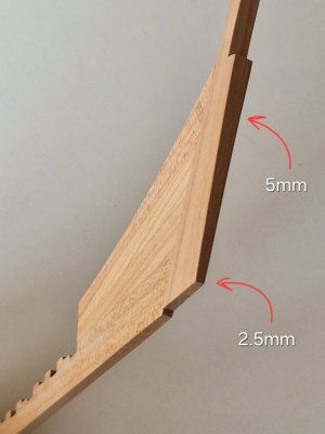
Well, no matter what, we continue. And let's start a little with the theory. In order for the lower skin boards to hide behind the part that holds the steering loops, you need to make the false keel thinner from 5 mm to 2.5 mm.

Alert 237.jpg

To do this, there is a template in the set, you just need to draw a line.

Alert 238.jpg

And then apply them on the ends.

Alert 239.jpg

According to the same scheme, you need to apply lines along both the false keel and the true keel.

Alert 240.jpg

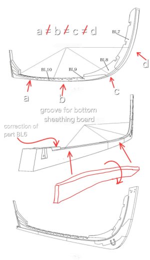
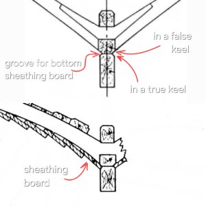
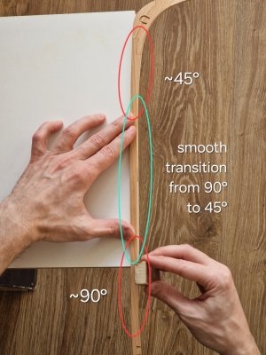
Here, too, a little theory. Why this groove at all? As shown in the picture above, it is needed so that the ends of the skin boards are inserted into it in front. And the bottom slot is needed so that the lowest skin board is inserted into it. And since the board from the steering wheel to the new goes at different angles, the groove should be appropriate. At the back, the board lies directly on this groove with an edge, and in the middle it twists almost 90 degrees.

Alert 241.jpg

And depending on the angle - the groove between the false and true keel will differ for the maximum lay of the end of the board.
To do this, I again apply markings on all surfaces.

Alert 242.jpg

It is very important to take into account the fact that from the bottom we will have a transition from the frames to this groove and you need to understand where this edge is.

Alert 243.jpg

To do this, I tried on a few frames to check where to put this line.

Alert 244.jpg

And taking into account the size of the overall grinding, I drew lines.

Alert 245.jpg

And now it remains only to remove everything in between and start with a false keel.
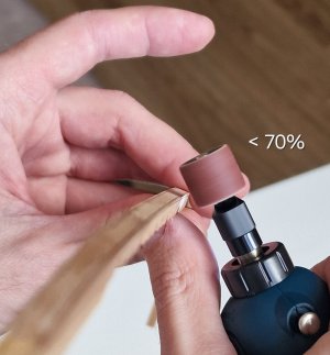
Where a lot of wood can be cut 70% neatly with an engraver.

Alert 246.jpg

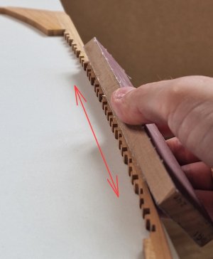
The rest should be modified manually with sandpaper glued to a flat board.

Alert 247.jpg

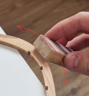
At the bend, I did as shown below. The main thing here is always to adhere to the correct angle so that the groove is with angles, and not in the form of a semicircle.

Alert 248.jpg

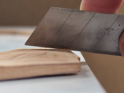
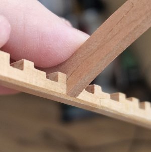
The evenness of grinding is easy to check with a blade, and if there is a semicircle, then you can scrape the belly with the same blade.

Alert 249.jpg

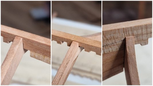
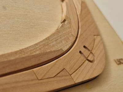
A good result is when the frame goes into the groove along one line.

Alert 250.jpg

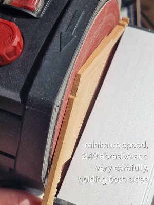
But it's easier, of course, to do it on a grinder. But here you need to understand that there will be no room for error. Therefore, the minimum revolutions, we hold with both hands, abrasive no more than 240 and very carefully remove the excess.

Alert 252.jpg

And as a result - it turned out like this...

Alert 253.jpg

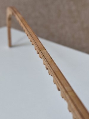
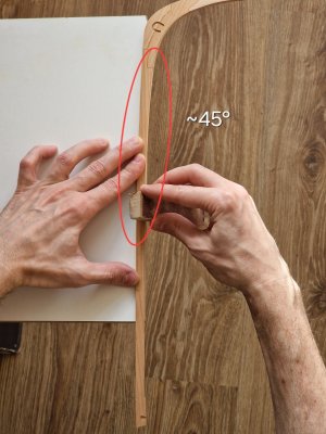
The keel is processed according to almost the same principle. The only thing, as I said, is that the groove is ground from an almost even angle to 45 degrees.

Alert 255.jpg
Alert 256.jpg

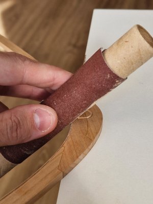
Well, for processing the concave side, I use sandpaper wrapped around the cylinder.

Alert 257.jpg

Well, the intermediate result is still without gluing.

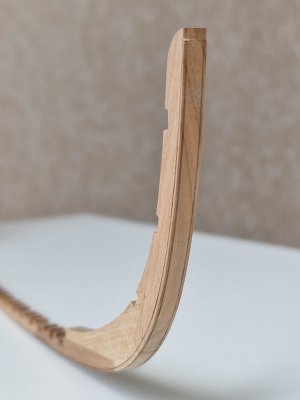
In the upper section, the groove from the middle position goes almost only to the keel...

Alert 258.jpg

Near the horseshoe - an almost uniform symmetrical groove...

Alert 259.jpg

In the middle, the groove gradually disappears on the keel and increases on the false keel, turning into a rear thinning...

Alert 260.jpg

Alert 261.jpg
Alert 254.jpg

This is where the contouring is over and now you still need to do a couple of little things and you can glue both keels together...

Alert 262.jpg

Ship-1
 
Last edited:
Really wonderfull backbone for your cutter.
Thank you! This base still has some things to improve before gluing, I'm working on it.


Very nice result, Sergey. Working on the sanding disc is very risky, but it turned out very clean.
Thank you very much. The secret is to process the perimeter manually, and everything that sticks out later - with a machine. And this way it is easier to control the angle. But yes, it was alarming))
 
2.4 Profiling, grinding and fitting of frames.

Well, no matter what, we continue. And let's start a little with the theory. In order for the lower skin boards to hide behind the part that holds the steering loops, you need to make the false keel thinner from 5 mm to 2.5 mm.

View attachment 514701

To do this, there is a template in the set, you just need to draw a line.

View attachment 514702

And then apply them on the ends.

View attachment 514703

According to the same scheme, you need to apply lines along both the false keel and the true keel.

View attachment 514704

Here, too, a little theory. Why this groove at all? As shown in the picture above, it is needed so that the ends of the skin boards are inserted into it in front. And the bottom slot is needed so that the lowest skin board is inserted into it. And since the board from the steering wheel to the new goes at different angles, the groove should be appropriate. At the back, the board lies directly on this groove with an edge, and in the middle it twists almost 90 degrees.

View attachment 514705

And depending on the angle - the groove between the false and true keel will differ for the maximum lay of the end of the board.
To do this, I again apply markings on all surfaces.

View attachment 514706

It is very important to take into account the fact that from the bottom we will have a transition from the frames to this groove and you need to understand where this edge is.

View attachment 514707

To do this, I tried on a few frames to check where to put this line.

View attachment 514708

And taking into account the size of the overall grinding, I drew lines.

View attachment 514709

And now it remains only to remove everything in between and start with a false keel.
Where a lot of wood can be cut 70% neatly with an engraver.

View attachment 514710

The rest should be modified manually with sandpaper glued to a flat board.

View attachment 514711

At the bend, I did as shown below. The main thing here is always to adhere to the correct angle so that the groove is with angles, and not in the form of a semicircle.

View attachment 514712

The evenness of grinding is easy to check with a blade, and if there is a semicircle, then you can scrape the belly with the same blade.

View attachment 514718

A good result is when the frame goes into the groove along one line.

View attachment 514719

But it's easier, of course, to do it on a grinder. But here you need to understand that there will be no room for error. Therefore, the minimum revolutions, we hold with both hands, abrasive no more than 240 and very carefully remove the excess.

View attachment 514720

And as a result - it turned out like this...

View attachment 514721

The keel is processed according to almost the same principle. The only thing, as I said, is that the groove is ground from an almost even angle to 45 degrees.

View attachment 514726
View attachment 514727

Well, for processing the concave side, I use sandpaper wrapped around the cylinder.

View attachment 514728

Well, the intermediate result is still without gluing.

In the upper section, the groove from the middle position goes almost only to the keel...

View attachment 514729

Near the horseshoe - an almost uniform symmetrical groove...

View attachment 514730

In the middle, the groove gradually disappears on the keel and increases on the false keel, turning into a rear thinning...

View attachment 514731

View attachment 514732
View attachment 514734

This is where the contouring is over and now you still need to do a couple of little things and you can glue both keels together...

View attachment 514733

Ship-1
A very nice explanation and outcome, Sergey. A solid base!
Regards, Peter
 
Back
Top