• Win a Free Custom Engraved Brass Coin!!!
    As a way to introduce our brass coins to the community, we will raffle off a free coin during the month of August. Follow link ABOVE for instructions for entering.

HMS Alert [1777] 1:48 POF by serikoff. (Two hulls: skeleton and fully rigged)

Hey Sergey,

Thank you very much for your information. It's always great to read about all the things you plan and create. Your construction skills are simply amazing. I'm a fan of your construction methods and explanations.

Best regards
Günther Ship-1
 
Hello,
Thank you very much for the detailed information. Perfect. That helps me a lot, thank you
I am very glad that it is useful to you, I will continue in the same spirit.

Hey Sergey,

Thank you very much for your information. It's always great to read about all the things you plan and create. Your construction skills are simply amazing. I'm a fan of your construction methods and explanations.

Best regards
Günther Ship-1
It's very nice to hear that. As long as there is time and opportunity to share the whole process - I do it. I myself need to make up a lot. I had a very long pause in modeling.
 
Small changes for you, but very big decisions for me. Lower railings "window sills."

This place (lower railings - window sills) turned out to be the most difficult for me in deciding how to implement it. Since I did not want to do in the kit on the second hull - due to the gaps between the railing and the racks. And so I finally figured out how to make sure that the work was minimal, but also the solution was as satisfactory as possible for me. I have not yet decided how I will do on the first hull. Most likely I will give a chance to the manufacturer's version with modifications, but I will leave the opportunity for my version.

So, the implementation of my decisions, which I came to after a few months of thought:
Alert 1149.jpg

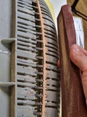
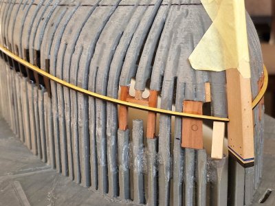
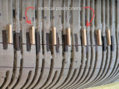
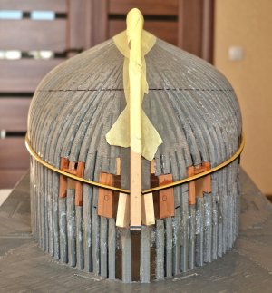
After I installed the vertical positioners, I rested them on the horizontal positioner along the hull.
Alert 1150.jpg

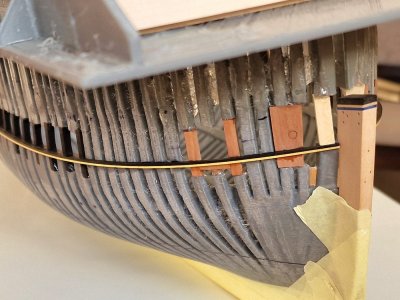
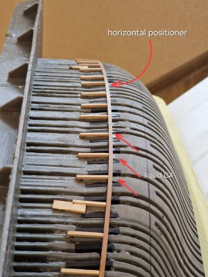
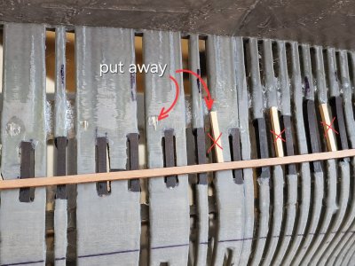
And looking ahead, I will say that all this will be cleaned, and now it served for accurate positioning of the "windowsills." And the first to remove the vertical stops, since they have already completed their task.
Alert 1151.jpg

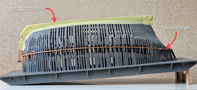
By the way, to keep the keel intact - I pasted it over with a protective tape.
Alert 1152.jpg

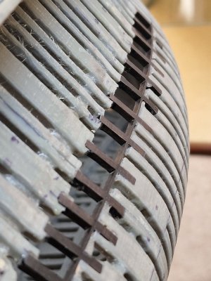
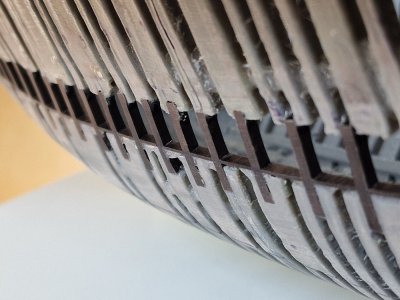
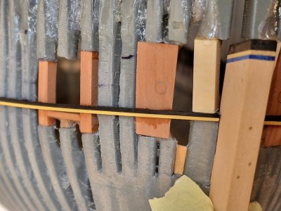
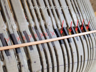
Then - I removed the plastic jumpers in the insertion area.
Alert 1153.jpg

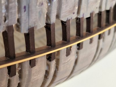
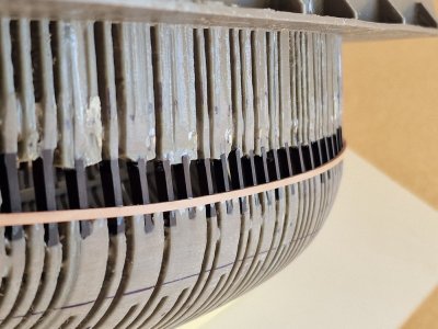
Now these inserts (railing drains) are free to fix the "sills."
Alert 1154.jpg

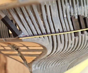
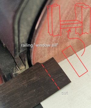
Well, the "windowsill" themselves (the middle part of the lower railing), as I did it.
Alert 1155.jpg

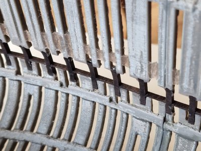
I measured the exact width of each span and cut out the corresponding blank.
Alert 1156.jpg

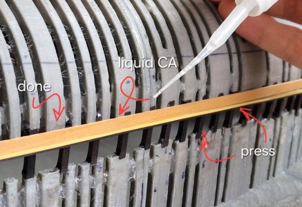
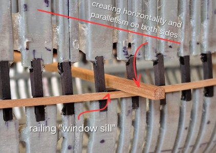
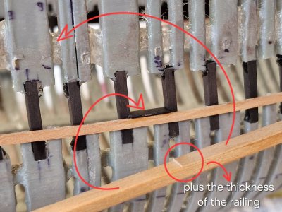
After that, I pressed it against the horizontal positioner with a bar that rested on two sides at once, creating parallelism and accurate horizontality.
Alert 1157.jpg

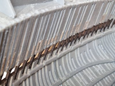
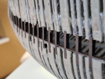
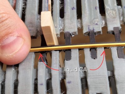
To maintain accurate horizontality, from the second side I added a thickness equal to the thickness of the "windowsill" to the bar. Fixed from the front on liquid CA by capillary deposition. Glue penetrated under the railing, gluing it to a horizontal positioner and even racks.
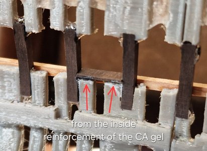
Alert 1158.jpg

And from the inside - I smeared CA gel, reinforcing this compound.

The idea is to then grind the surplus those that remain from the inside and grind the outside level with the body not only the surplus, but also the entire positioner, since it will also fulfill its functions and will no longer be needed.
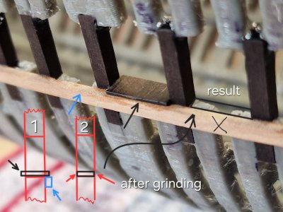
Alert 1159.jpg

And then, in order to smoothly glue the outer and inner parts of the railing, I will glue another vertical positioners...
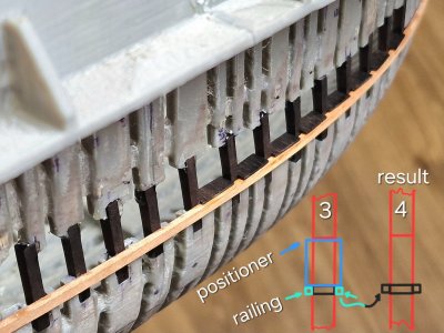
Alert 1160.jpg

... and in the end there will be such a result: the lower railings - consist of three parts: "window sills," external and internal. And after gluing, they should visually form one part. Since the black hornbeam is logically black, all seams should be practically invisible.

At first glance - the implementation is difficult, but! I thought a lot about this and did not come up with a way in which accuracy can be achieved in the least amount of time.

Making railings with square holes is not an option - because it is not possible to achieve accuracy without a milling machine in multiple lines. And any other method still leads to errors or significantly lengthens the process, which is also not acceptable. Therefore, it is easier to make a lot of positioners in a couple of minutes and then eliminate them, but on the other hand, do everything symmetrically and smoothly and most importantly quickly, which is most important for me.
 
Sill-railings.

So, after grinding...

Alert 1161.jpg

... which took place in the same way as before... the result was as follows inside:

Alert 1162.jpg

Alert 1163.jpg

And outside:

Alert 1164.jpg

Alert 1165.jpg

Alert 1166.jpg

The result suited me and I am glad that this is the process behind.

There are 135 parts on board (not taking into account all the momentary positioners)... continue on.

By the way, I continue to try different options for wood coated with oil and bitumen... I'll tell you about it a little later.
 
There are few updates, not much time to engage in hobbies. Plus, in several directions there are continuous dead ends, you have to think a lot about how to do what, and this takes a lot of effort and a lot of time. And the motivation from this falls. I want to do a lot, but you start one thing, but you still need to do the second, and to do this you also need the third, and to start the third, you need the fourth and fifth, and so on. Now the most important stage is the miscalculation and marking of the skin belts. And if you do it at random, then the result will be the same. So I sit, calculate, I think I decide...

... in the meantime, I decided to finish with the inserts.

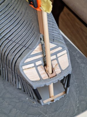
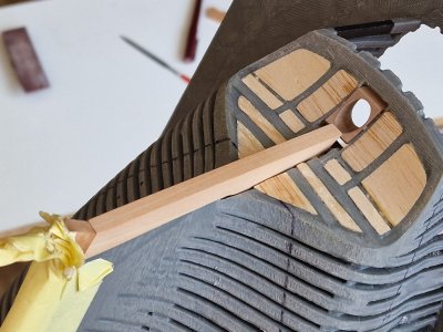
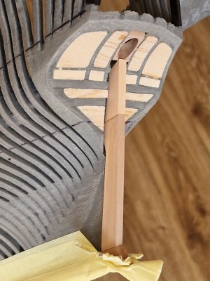
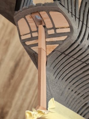
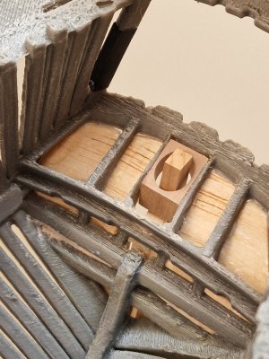
To make it easier to glue the skin, he sewed up the voids with balsa and made a small conductor, along which he installed a hole under the steering wheel.

Alert 1167.jpg

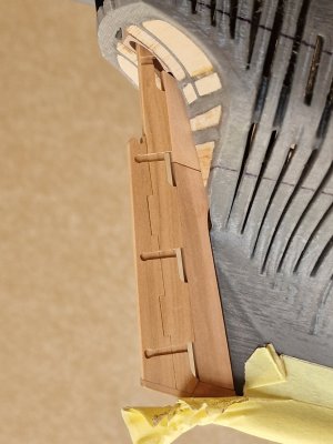
The steering wheel axis was a round workpiece. Then he made a stern and adjusted it to its place.

Alert 1168.jpg

And since this part, like the rest, intersects the waterline, it will be two-tone.

Alert 1169.jpg

He marked the waterline in the same way as before on the front fragment. Glued from two parts: light and dark pear. So far, the difference is not very visible, but after the oil the difference will be very noticeable.

Alert 1170.jpg

In the future, the steering wheel will be made according to the same principle. In the meantime, I tried on the steering wheel from the first hull (skeleton).

Alert 1172.jpg

Alert 1171.jpg

And now the most difficult thing awaits me - fixing the outer part of the lower railing-windowsill, and then 2 belts of rails and a reinforced black belt, after which you can sheathe under the stern and then continue the rest of the sheathing... And I can't wait, but I also understand how difficult it will be...

P.S. there is still a lot of work on the sternpost, so it is not yet finished and not fixed. And yet, I forgot to clarify, the stem from above is 6 mm, and from below 4.5 mm, the steering wheel will be the same. When I completely refine it and fix it on this in detail.
 
Last edited:
I breathed a sigh of relief today. Nobody like @dockattner will understand me. Painful deliberation and calculations have finally paid off.
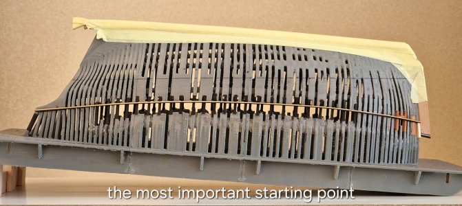
The starting point today was laid.

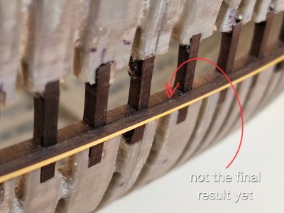
The outer part of the sill-railings, which will serve as the foundation from which the sheathing belts will go and down and up. Until the end, I didn't quite understand how I would implement it, and although the result is not yet final (you still need to clean the glue and smooth the joint), something is already looming!

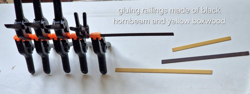
So, I cut 1x10 mm blanks from black hornbeam and yellow boxwood...

Alert 1173.jpg

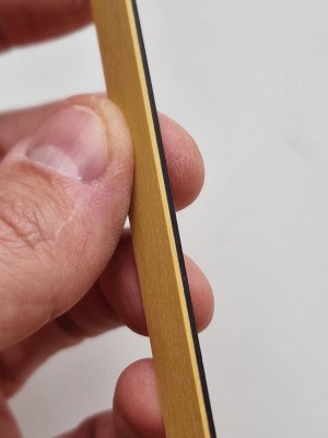
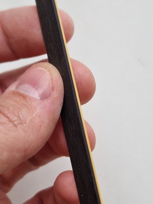
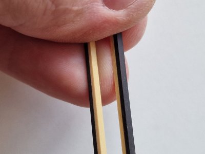
Glued so that the finished part is enough for the entire length of the case and so that the joints do not intersect. As a result, 2x10 mm blanks were obtained.

Alert 1174.jpg

Alert 1175.jpg

After grinding, they became 1.8x10 mm. Then I cut 1.8x2 mm parts from them.

Alert 1176.jpg

In the front of the hull, the bend is stronger, so I made a small radius before fixing with an iron so that the rail would not break.

Alert 1177.jpg

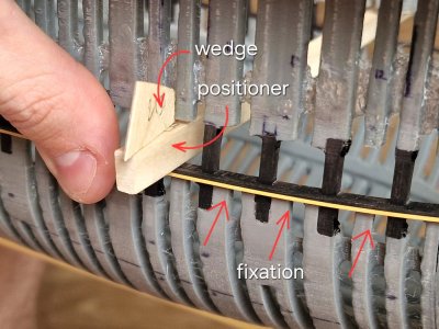
To perfectly connect the outer and middle parts of the railing, I used a positioner that is fixed in the port hole with a wooden wedge. Fixed gradually, moving the positioner and pouring liquid CA under the railing.

Alert 1178.jpg

Naturally, I will try to remove everything that will interfere with further work or that will be visible. But for the most part, it will close with other details.

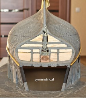
And here is the result! Everything is plus or minus symmetric, so I'm happy.

Alert 1179.jpg

Alert 1180.jpg

Alert 1181.jpg

Alert 1182.jpg

Alert 1183.jpg

Alert 1184.jpg

Alert 1185.jpg

I understood. that I will not leave the joints in any way, but this zone will still be finalized and on black hornbeam these joints will be little noticeable..

Alert 1186.jpg

Everything is far from perfect, as we would like, but I think, in general, when there is a model assembled - the general view will cover all the shortcomings. In any case, I hope so.

Alert 1187.jpg

Now - things will go faster. You just need to glue the skin boards and watch the symmetry. The fun will start near the waterline... eh...

Ship-1
 
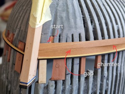
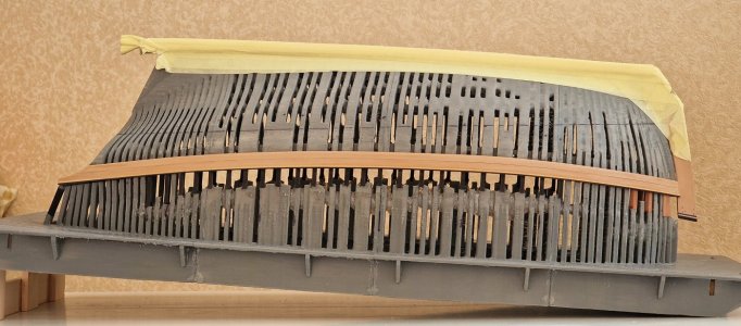
I expected the skin to move not quickly, but today I glued 2 belts each (4 planks) ... and this despite the fact that I had these 4 boards prepared a long time ago, and I selected the only 4 that came up and reduced the width from 6 to 5 cm. So I had no room for error at all.

Alert 1188.jpg

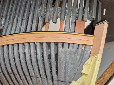
The fixation itself is not that complicated. It is necessary to press, spill with liquid CA so that it penetrates capillarity under the board and is ready. I still shed from the inside to strengthen the connection. And at the end I will fill all the gaps with glue and this forms one monolith. It was more difficult to clean, fit and chamfer everything for a better fit and to create gaps between the boards.

Alert 1189.jpg

But the result suited me.
Alert 1190.jpg

After grinding, the result was even better...

Alert 1191.jpg

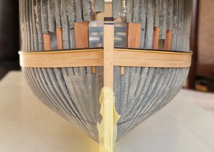
Well, do not forget about symmetry either.

Alert 1192.jpg

Alert 1193.jpg

Alert 1194.jpg

From this perspective, in the hand - it is already beginning to resemble a ship.

Alert 1195.jpg

The next in line is the power belt (rubbing piece). It will be two-layer. Since the black hornbeam bends poorly, I decided to do first 0.8-0.9mm and on top of the main layer, so that in total it would be visually visible that the power board is thicker than ordinary boards.
 
Hey Sergey,

I agree with you. Sometimes building has to wait until you realise what you want to do next. I've been there and yes, it always takes time. But it's time that's worth it. Because it's better to build purposefully and correctly than to tear everything down and redo it later.
As always, really wonderful work. You have my respect!

Cheers, Günther. Ship-1
 
Definitely one of the most unusual and interesting builds I have ever followed. Thanks for sharing each of the steps along the way.
Allan
As always, thank you for so much appreciation. I am glad to try and glad that it brings not only me in truth a great mood.

Hey Sergey,

I agree with you. Sometimes building has to wait until you realise what you want to do next. I've been there and yes, it always takes time. But it's time that's worth it. Because it's better to build purposefully and correctly than to tear everything down and redo it later.

As always, really wonderful work. You have my respect!

Cheers, Günther. Ship-1
Glad I'm not alone. Thank you for your words, and further, I'm sure it should be even more interesting.
 
Barkhout. (or sheer wales, wale, rubbing strake or rubbing strip).

I am very glad that I started this project... that at the same time I am building two hulls. And for me there is a lot new in this project. The first kit that I started (and by the way this is the simplest of all), and definitely a lot of new things every time.

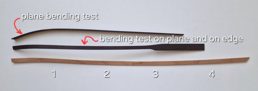
Today I was doing barkhouts (powerboards). And for the first time I bent a black hornbeam in all three planes. Both plane and edge.

Earlier I said that I would make barkhouts two-layer, because I did not think that I could bend the board in 2mm and a tween of almost 8mm, but I tried it and it turned out.

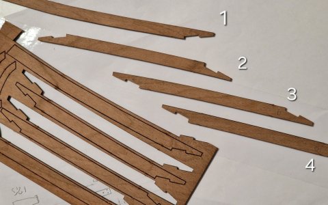
First, I glued 4 parts from the copy geometry kit.

Alert 1196.jpg

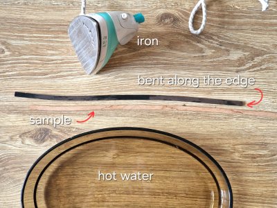
Then I tried to bend the rail flat, it's easier, but the radius is not small and I had to check if the board would crack. And then I bent another sample and over the rib... then I realized that this was a working option.

Alert 1197.jpg

Bent as always: first I soak a fragment of the board in hot water and then press the wildebeest in the right direction with an iron.

Alert 1198.jpg

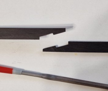
First, I bent along the edge and checked the geometry with a sample from the set. And then he bent along the plane and tried on the body. When everything became according to the geometry of the case, I glued two fragments through the lock.

Alert 1199.jpg

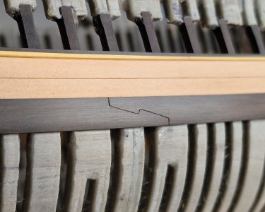
The castle was made with a file. I started one fragment, then applied it to the second and scratched the profile of this lock with a blade. Then you just had to cut out the second lock by scratches.

This had to be done since I did not have a fragment of black hornbeam for the entire length of the case, so one lock will be real and two more will be scrawled after fixing. So I would make all the connections an imitation (so easier), but the length did not allow.

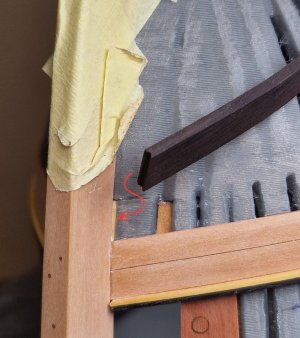
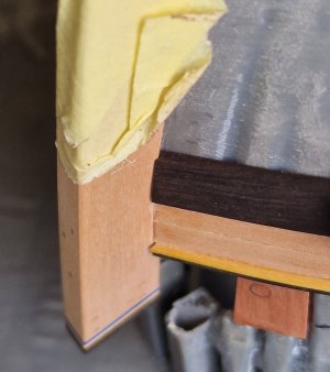
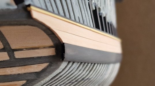
Before fixing, I made a special recess on the front so that the board goes around the corner and its edge goes deep, fixing there, strengthening the fixation.

Alert 1200.jpg

Alert 1201.jpg

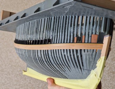
I glued it like this: the front part on the CA gel positioning only the front fragment of the board 4 cm long. Then I glued everything to the CA liquids according to the same principle as all the boards before. Pressed - spilled (capillary) liquid CA into the seam between the board and the hull and there gradually moved to the stern, glue 4-5 cm at a time. It is important that when held, the board fits tightly to both the adjacent board and the body. Otherwise, there will be gaps and distortion of geometry.

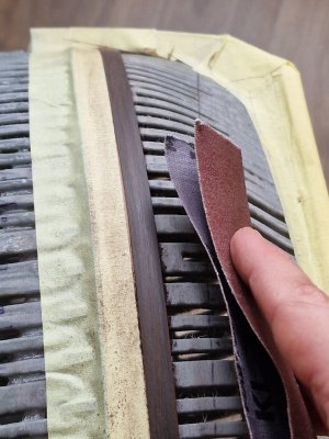
Then it was necessary to grind everything and give the board the correct geometry in the form of a round.

Alert 1202.jpg

Alert 1203.jpg

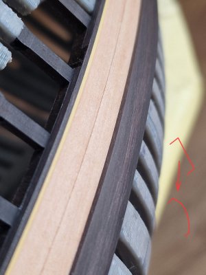
I removed the remains of glue in the joint between the boards and under it with a blade. As you can see, there are no traces. To strengthen the connection, I spilled liquid CA from the inside between the frames. Then all these spaces will still be spilled with CA gel, so that for sure nothing comes off over time.

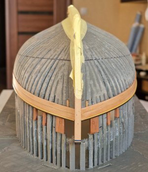
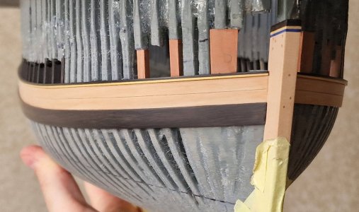
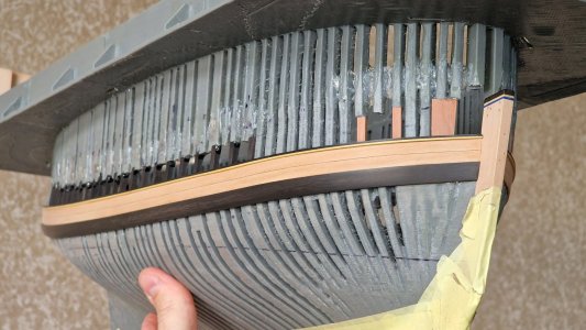
And here is the result, while on one side.

Alert 1204.jpg

Alert 1205.jpg

Lock so that it can be seen done with slits. And this principle will be in all connections for greater visualization, especially when bitumen gets into the cracks.

Alert 1206.jpg

The result is obviously already satisfactory.

Alert 1207.jpg

Ship-1
 
I LOVE that the strake of wales has been tapered in thickness so it sits properly in the rabbet at the stem. This is something that was always done on the ships and contemporary models but looking at the build logs it appears that some (most?) kit manufacturers are unaware of this requirement in construction.
Allan
 
I LOVE that the strake of wales has been tapered in thickness so it sits properly in the rabbet at the stem. This is something that was always done on the ships and contemporary models but looking at the build logs it appears that some (most?) kit manufacturers are unaware of this requirement in construction.
 
I LOVE that the strake of wales has been tapered in thickness so it sits properly in the rabbet at the stem. This is something that was always done on the ships and contemporary models but looking at the build logs it appears that some (most?) kit manufacturers are unaware of this requirement in construction.
Allan
Hello AllanKP69, with all due respect to those who model with kits, in my opinion there is no comparison between kits and building from scratch; a donkey cannot become a racehorse. Frank. Scumi Serikoff, I apologize for invading your workshop.
 
Ciao Frank
Regarding the wales, IMHO there is no reason the kit builder cannot taper the thickness of the wales so they can rest properly in the rabbet. It has nothing to do with scratch versus kit. It is just a matter of spending a few minutes sanding the forward few feet of the wales so the end is the same thickness as the surrounding planking. I would not expect a kit to preshape it due to the cost, but there is no reason they cannot show with words or sketch that the wales need to be tapered if they are to rest in the rabbet. This is really a basic thing so why not add a sketch are a few words to explain it? The builder can then choose to do it or ignore it. Just a thought.:)
Allan
Dear Allan, to avoid misunderstandings (translation), I avoid writing .Frank
 
I LOVE that the strake of wales has been tapered in thickness so it sits properly in the rabbet at the stem. This is something that was always done on the ships and contemporary models but looking at the build logs it appears that some (most?) kit manufacturers are unaware of this requirement in construction.
Allan
@AllanKP69, are you and I looking at the same pictures? I saw a comment coming but not the one you posted ROTF.
 
Hi Paul
The two that are the most clear for me are below. At the bow it is not exactly the same thickness as the strakes above, but much thinner than midship so seat well in the rabbet. Compare it to the second photo which is commonly seen on modern builds but never on contemporary models, and presumably never on the ships themselves. If anyone has pictures or scantlings based on contemporary information that show the wales standing proud at the rabbet I would really appreciate a chance to see this.
Allan

1756044437902.jpeg
1756044235471.jpeg
 
Hi Paul
The two that are the most clear for me are below. At the bow it is not exactly the same thickness as the strakes above, but much thinner than midship so seat well in the rabbet. Compare it to the second photo which is commonly seen on modern builds but never on contemporary models, and presumably never on the ships themselves. If anyone has pictures or scantlings based on contemporary information that show the wales standing proud at the rabbet I would really appreciate a chance to see this.
Allan

View attachment 539666
View attachment 539665
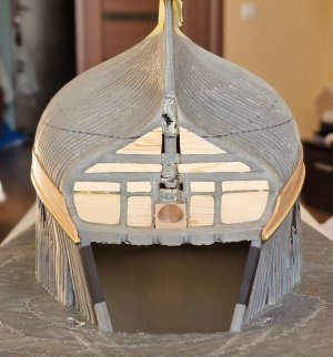
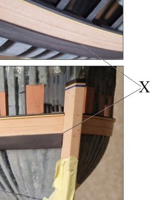
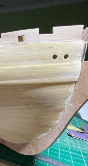
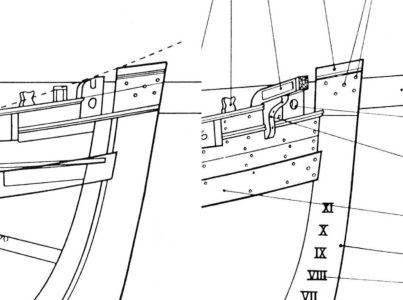
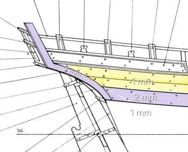
I don't want to disappoint you, Allan, but this is the angle of the photo. Now I will try to explain it to you in order. I completely agree with you that power boards are often (but not always) narrowed in the front and back. But this was often done so that a very thick board could bend. On cutters (where the board thickness is not very thick, narrowing was not done, this is clearly visible in the anatomy drawings. This is what I am guided by.

20250824_210830.jpg

It also did not narrow at the stern. Because the power board was equal to the thickness of the rear part (half-moon) and in my scale it is 2 mm, and the standard board is 1 mm.

Screenshot_20250824_210306_Gallery.jpg

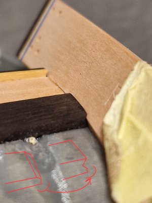
Here is a photo angle that shows this step and the method of wedging into the groove for the boards. In the power board, part of the board simply goes on top and forms a small step, but part of the board still fits into the groove for the board on the keel.

20250824_210408.jpg

But it does not matter that this is a universal solution, but only for this ship. For another, it will be a narrowing, as you say. Most likely, this unit is not a constant, but can vary in implementation depending on the dimensions, thickness of the boards and the rank of the ship. But the fact that many ships had a narrowing is definitely true. But judging by the drawings, not on this cutter.


@AllanKP69, are you and I looking at the same pictures? I saw a comment coming but not the one you posted ROTF.
How everything changes depending on the viewing angle. ;)

Hello AllanKP69, with all due respect to those who model with kits, in my opinion there is no comparison between kits and building from scratch; a donkey cannot become a racehorse. Frank. Scumi Serikoff, I apologize for invading your workshop.
Always happy to discuss ship topics:cool:
 
Last edited:
Back
Top