


- Joined
- Jul 27, 2021
- Messages
- 705
- Points
- 403

The interesting thing is, you can really, really see how damn neat you build 

 |
The beloved Ships in Scale Magazine is back and charting a new course for 2026! Discover new skills, new techniques, and new inspirations in every issue. NOTE THAT OUR NEXT ISSUE WILL BE July/August 2026 |
|
 |
As a way to introduce our brass coins to the community, we will raffle off a free coin during the month of August. Follow link ABOVE for instructions for entering. |
|

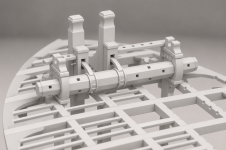
It’s a shame that AI often fills in details with nonsense or just makes things up when it doesn't see or understand the logic of the scene (in this case, the carlings are actually the same thickness as the beams, but they just happened to fall into the shadow). But overall, it’s a really cool idea! Thanks for the praise—hearing it from you makes it doubly gratifying!

Just flawless! nothing more, nothing less. Amazing job and a bunch of smart solutions you kindly share with us. Appreciated!Chapter 27. On the Decks (Part 5)
Аnchоr Windlass.
2/
I lost practically a week to COVID and couldn't do anything. To avoid wasting all that time, I worked concurrently on 3D modeling the decorative elements and the figurehead for the *Victory*. So, let's continue with the anchor mechanism. Because errors in the kit parts mean the assembly for the first hull differs slightly from the second, I am building them one after the other rather than in parallel like the other components. The photos show all the stages, so without further ado:
View attachment 641018
View attachment 641019
View attachment 641020
View attachment 641021
View attachment 641022
View attachment 641023
View attachment 641024
View attachment 641025
View attachment 641026
View attachment 641027
This time, I experimented with blackening. I had noticed that, over time, neon-like spots would appear in isolated areas—resembling the sheen of gasoline on wet asphalt (something I’ve shown before). Upon investigation, it turns out that internal processes continue within the electroplated copper; the blackening solution's reagents cause something to leach out, though wiping the surface with alcohol helps remove it. So, this time, I tried degreasing the parts before blackening. I started with an initial 18-minute soak in a 1:5 solution of blackening agent and water. After rinsing, and without letting them dry, I brushed off the residue while the parts were still submerged in the rinse water. Next, I transferred the wet parts directly into a 1:3 solution for 9 minutes. Immediately after rinsing—and again without drying—I dropped them into alcohol. Only then did I dry them off. Finally, I removed the surface film and polished the pieces using a soft attachment at very low speed. This produced a more pronounced metallic luster. The copper didn't turn quite as black as it usually does with my standard method, but the polishing action compensated for that. I’ll be monitoring the results to see how things change. My test pieces (anchors) had already started turning blue again, so the alcohol wipe was only a temporary fix. Acting on advice from an AI, I coated them with Danish oil and Tung oil. I applied the oil with a cloth and buffed it dry after just a few seconds. The AI claims that a microscopic layer remains, sealing out oxygen and preventing further changes to the parts. We’ll see! I’ll make a separate post about this after a couple of months of observation. On the plus side, applying and wiping off the oil doesn't alter the color or sheen; everything looks exactly as it did before. So, if this helps prevent blue spots, I’ll definitely be oiling the blackened metal. Here is the result after the blackening process. It’s a shame the photos can’t quite capture the true color, but I really like the texture and the hue. The interplay of lively sheen and deep shadows creates a sense of depth, preventing everything from blurring into a single black blob—something I really dislike.
View attachment 641028
View attachment 641029
View attachment 641030
View attachment 641031
View attachment 641032
View attachment 641033
For storage, I use dental crown boxes (for those who don't know, I am a prosthodontist)
View attachment 641034
View attachment 641035
View attachment 641036
View attachment 641037
View attachment 641038
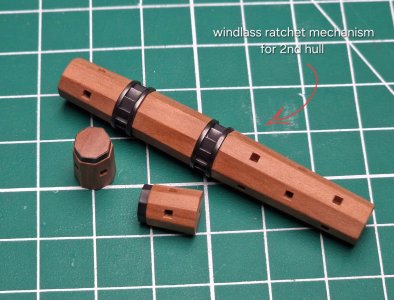
Next is the ratchet mechanism itself, featuring an octagonal beam for the anchor rope...
Blender ?

True storyWorld class modeling, Sergey. Respect.
....in that case I will keep my ships far away from any AI programsThe interesting thing is, you can really, really see how damn neat you build
 .

There is a edit-option on the left bottom of your post ………Sorry, spell check keeps changing your name!

Thank you very much. I’m glad to see you here; it’s been a while.Just flawless! nothing more, nothing less. Amazing job and a bunch of smart solutions you kindly share with us. Appreciated!
No, this is just an image generated using AI; that was mentioned a couple of posts back.Blender ?
True story
Thank you very much for your interest and your kind wishes. Don’t be too hard on yourself—you’re doing a great job!....in that case I will keep my ships far away from any AI programs
Brilliant as always Sergey. You guys stay safe.
Cheers Grant

Sergio,
unbelievable precision my friend. You are an amazing craftsman.
Thank you very much. Please don’t worry—it’s just one of the ways my name is inflected in different countries, so you didn’t make a mistake.Sorry, spell check keeps changing your name!
There is a edit-option on the left bottom of your post ………
View attachment 643572
Then you can make adjustments to your text and save it.
Regards, Peter

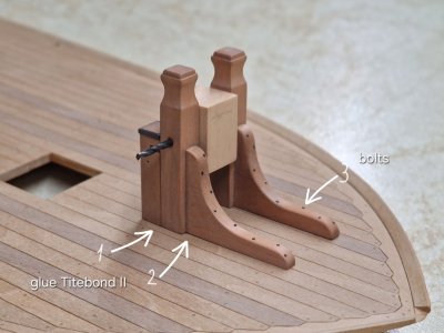
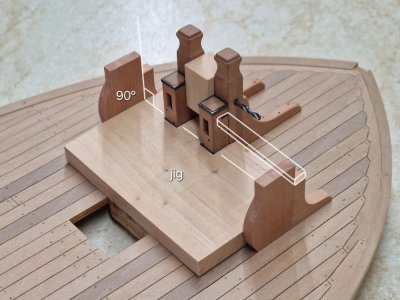
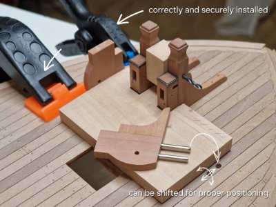
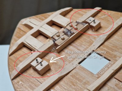
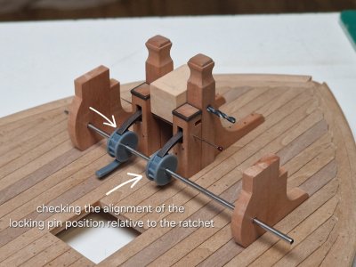
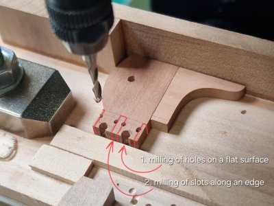
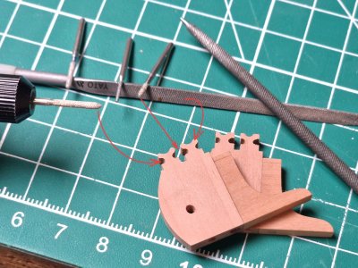
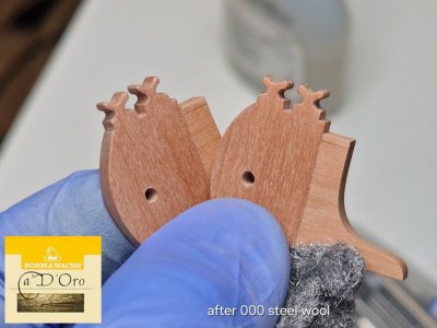
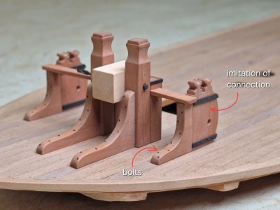
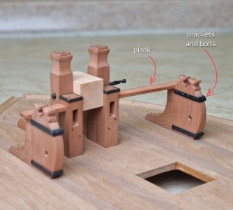

Hallo Sergey, einfach herrlich zu sehen, wie Du mit großer Überlegung und fachlichem Können wunderbare Ergebnisse erzeugst. Trotz der aufkommenden Schwierigkeiten. Immer wieder schön, wie Du die einzelnen Arbeitsschritte zeigst. Deine Dokumentation der einzelnen Schritte ist für alle hier eine sehr große Hilfe. Auch welches Werkzeug Du nutzt und einsetzt. Das ist wie eine „Schatzkammer“. Auch das Aufzeigen von Probleme und „Misserfolge“ ist absolut hilfreich und ermöglicht uns im Vorfeld nicht die gleichen Probleme zu erleben. Deine Ergebnisse sprechen Bände. Das wird ein großartiges Modell. Danke für's zeigen. Ich freue mich über jeden Beitrag von Dir.Kapitel 27. An Deck (Teil 5)
6/
Ankerwinde des 2. Rumpfes.
View attachment 644188
Wo die Vorgehensweisen denen ähneln, die ich bereits beschrieben habe, werde ich nicht ins Detail gehen; Stattdessen zeige ich einfach das Endergebnis, wie es auf dem Foto oben zu sehen ist.
Und nun zu einem etwas heiklen Thema… Ich arbeite seit drei Wochen an diesen beiden Verankerungsmechanismen – es war eine der schwierigsten Phasen des Baus. Ich bin froh, dass ich mich entschieden habe, die vorgefertigten Halterungen für den Ratschenmechanismus (im Bausatz enthalten) zu verwenden, anstatt sie selbst zu bauen; Die selbstgebauten Halterungen für den zweiten Satz haben die meisten Probleme bereitet. Mit diesen Bauteilen glaubte man von Anfang an alles und blieb es bis zum Schluss. Unter anderen Umständen hätte ich alles neu gemacht, aber angesichts der Komplexität und der bereits investierten enormen Zeit habe ich beschlossen, sie so zu lassen. Ich arbeite mit einer 3-fach vergrößerten Fernglaslupe, daher fällt mir jeder einzelne Fehler auf – und an diesen wenigen Teilen gibt es mehr Mängel als am gesamten Rest des Modells zusammen. Ich habe auch mit einer Schwärzungstechnik experimentiert, die sich als ziemlich schlecht erwies – die Oberfläche war extrem empfindlich. Ich habe sie dreimal erneuert, und trotzdem gibt es immer noch Stellen, an denen sie abgeplatzt ist. Ich habe beschlossen, diese Abplatzungen einfach zu akzeptieren; Ich werde sie so behandeln, als wären sie angemessen angebracht – um Rost zu simulieren. Außerdem habe ich mich verrechnet und das Kniegelenk ist zu kurz geworden, sodass ich zusätzliche Stücke ankleben musste. Theoretisch werden diese Stellen komplett von der Takelage verdeckt. An einer anderen Stelle riss der Fräser ein Stück Holz heraus, das ebenfalls ausgebessert werden musste. An anderer Stelle rutschte ein Bohrer ab und beschädigte die Oberfläche in der Nähe eines der Schäkel. Die Schäkel selbst neigten zum Verformen – die Bolzen ließen sich nicht lang genug fräsen und wollten einfach nicht richtig in die Löcher. Der absolute Höhepunkt kam aber, als ich versuchte, die Position eines Teils leicht zu korrigieren – und es brach sauber in zwei Hälften, entlang genau der Maserung und entlang der Bohrung für einen Bolzen… Ich dachte, das wäre das Ende. Und das geschah mit einem komplett fertigen Teil, an dem ich tagelang gearbeitet hatte! Zum Glück brach es so, dass die Rückseite intakt blieb; Ich habe die Bruchstelle mit PVA-Kleber übergossen (Sekundenkleber ist in so einem Fall absolut tabu), und da die Bruchkanten perfekt zusammenpassen, ist die Naht kaum zu sehen. Kurz gesagt, alles, was bei diesen beiden Stützen schiefgehen konnte, ging schief – und noch einiges mehr… Ich habe alles fotografiert und mich ziemlich mies gefühlt. Aber ich zeige sie euch nicht, denn 90 % dieser Mängel sind entweder mit bloßem Auge nicht sichtbar oder nur von unten aus einem bestimmten Winkel erkennbar – was angesichts des Decks und der Rumpfseiten unmöglich ist. Bei meinem Perfektionismus könnt ihr euch nicht vorstellen, wie schwer es mir ist, das alles zu akzeptieren… aber ich werde es definitiv nicht nochmal machen; Faulheit und gesunder Menschenverstand haben am Ende gesiegt, hahaha.
View attachment 644189
View attachment 644190
View attachment 644191
View attachment 644192
View attachment 644193
View attachment 644194
View attachment 644195
View attachment 644196
View attachment 644197
Als Nächstes steht die Fertigung des Ratschenmechanismus an – hoffentlich bin ich mit diesem Schritt dann fertig; er hat sich als ziemlich schwierig für mich erwiesen...

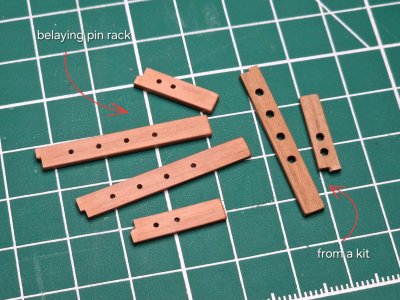
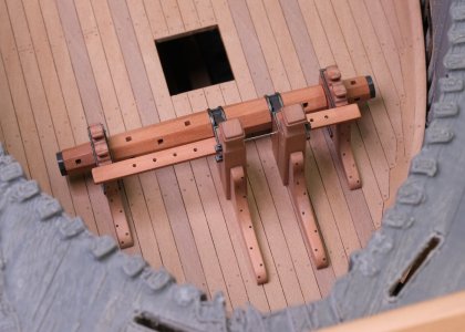
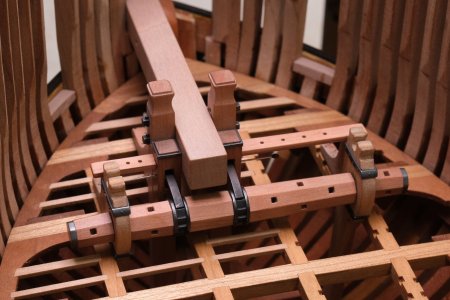
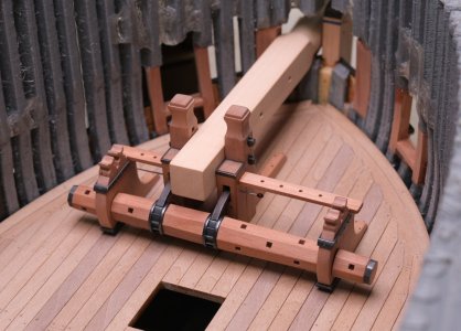
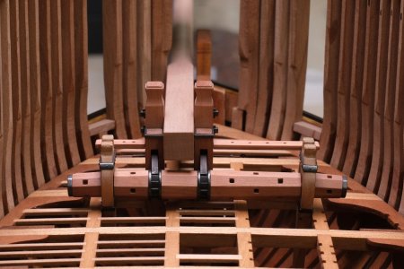
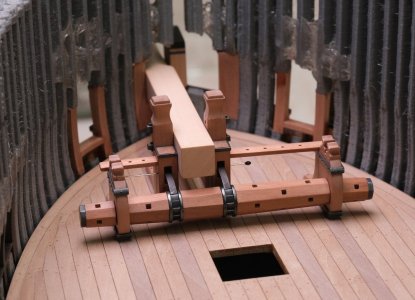
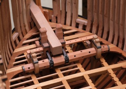
Unfassbar schöne Teile. Man muß sich die Teile in der Vergrößerung anschauen, um zu sehen wie perfekt sie geworden sind. Einfach grandios Sergey. Auch hier wieder das Aufzeigen der einzelnen Schritte dazu. Eine bessere Anleitung kann man sich nicht vorstellen.Danke fürs Zeigen.Kapitel 27. An Deck (Teil 5)
7/
Ankerwinde
So, das ist nun endlich der letzte Teil der Herstellung der Ankerkomponenten – hurra!
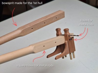
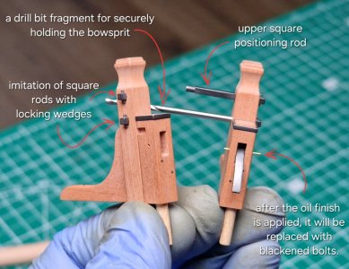
Ich habe beschlossen, die Bolzenhalterung neu zu bauen, bin mir aber noch nicht sicher, wie ich die Bolzen selbst anfertigen soll. Laut der Anleitung sollen sie quadratisch sein – passend zu den quadratischen Löchern in der Halterung –, aber ich bin da sehr skeptisch; ich habe noch nie quadratische Bolzen gesehen. Ich werde das aber erst kurz vor der Montage klären. Den Ratschenmechanismus und den Bugspriet habe ich bereits fertiggestellt.
View attachment 645395
View attachment 645397
View attachment 645398
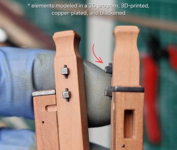
Beim ersten Rumpf musste der Bugspriet etwas dünner gefertigt werden, da die Bolzen bereits einen gewissen Abstand hatten und er sonst nicht passte. Optisch fällt das aber kaum auf, vor allem nicht, wenn die Rumpfteile nicht nebeneinander, sondern an verschiedenen Modellen zu sehen sind. Ich habe mit demselben Werkzeug, das ich bereits gezeigt habe, quadratische Löcher in die Bugspriete gebohrt. In den Bohrteilen sind diese Löcher rund, da sich die Form des äußeren und inneren Teils ändert. Die Bohrteile und den Bugspriet verbinde ich mit einem Bohrerstück, das innen liegt und seitlich mit quadratischen Teilen und Sicherungskeilen verschlossen wird.
View attachment 645402
View attachment 645403
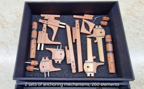
Die Komponenten sind derzeit demontiert und warten auf die Ölbehandlung... es handelt sich insgesamt um 260 Teile (ohne die für die Latten verwendeten Dübel).
View attachment 645404
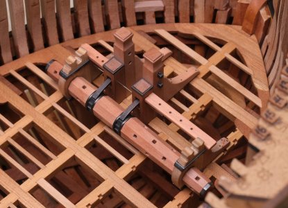
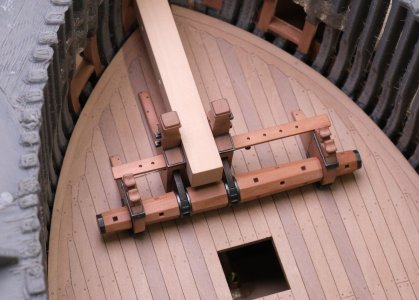
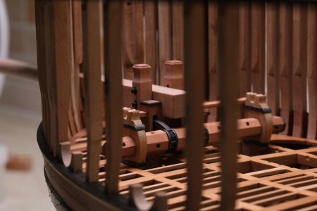
Und hier das Zwischenergebnis – eine Trockenpassung:
View attachment 645405
View attachment 645406
View attachment 645407
View attachment 645409
View attachment 645410
View attachment 645412
View attachment 645414
View attachment 645416
View attachment 645417
Als nächstes steht die Sicherung des Unterdecks auf dem zweiten Rumpf und die Installation der Beleuchtung darauf auf dem Programm...