You are using an out of date browser. It may not display this or other websites correctly.
You should upgrade or use an alternative browser.
You should upgrade or use an alternative browser.
HMS Blandford 1720 in scale 1:48 by Modelship Dockyard [COMPLETED BUILD]
Very good details with f.e. the table- I like it very much 
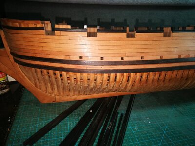
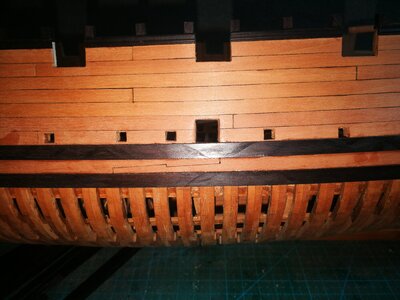
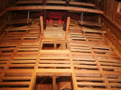
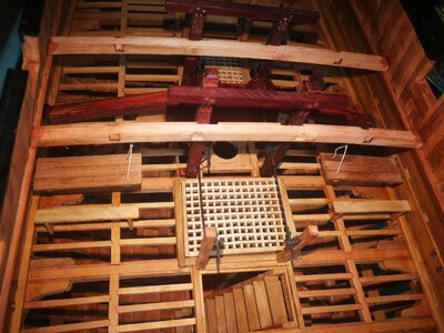
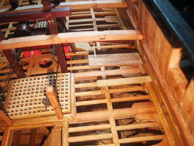
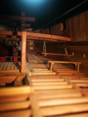
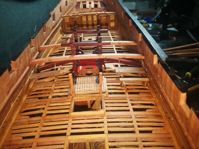
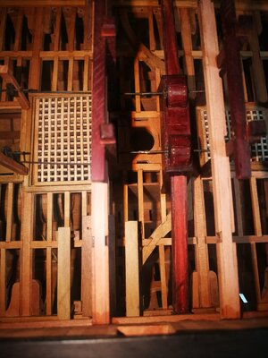
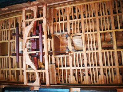
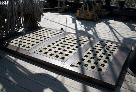
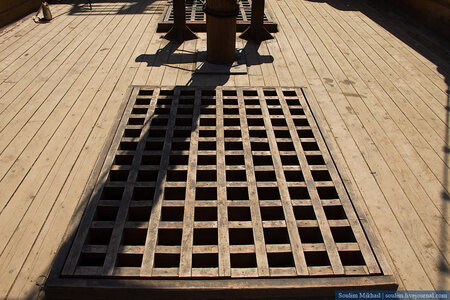
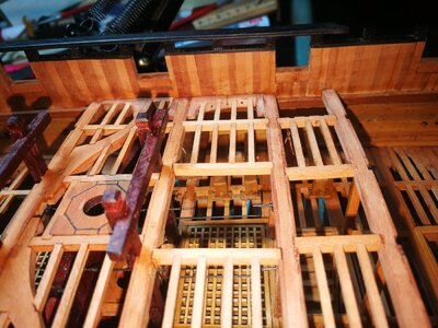
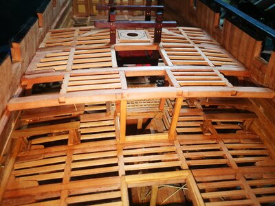
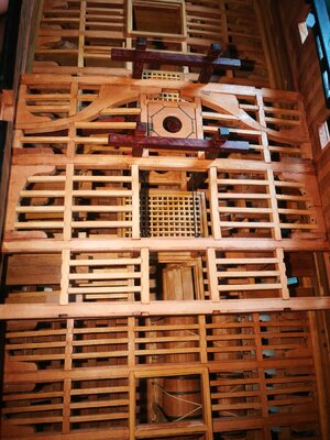
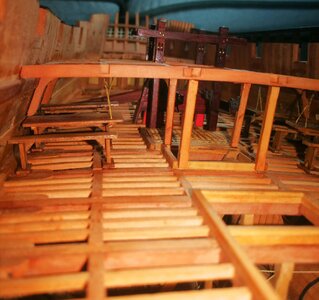
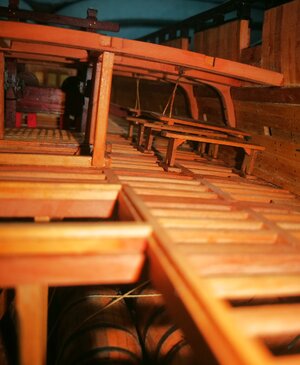
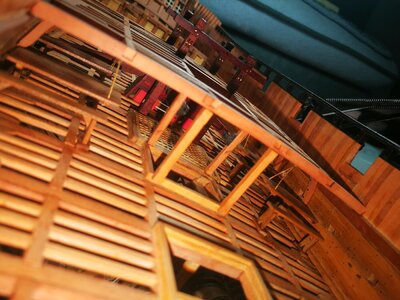
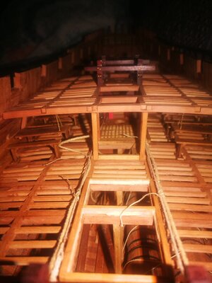
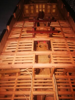
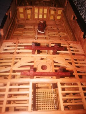
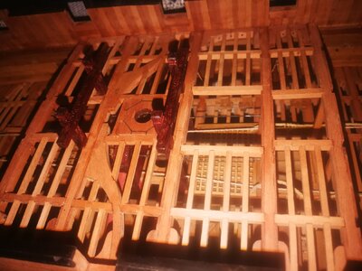
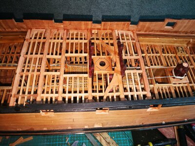
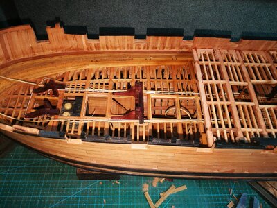
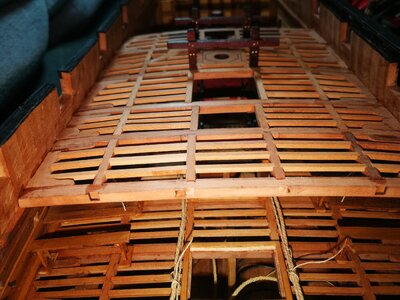
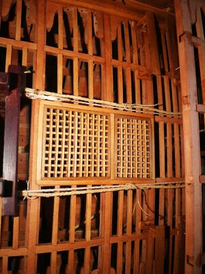
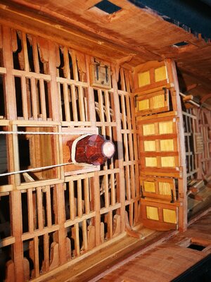
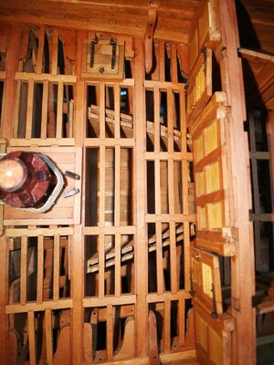
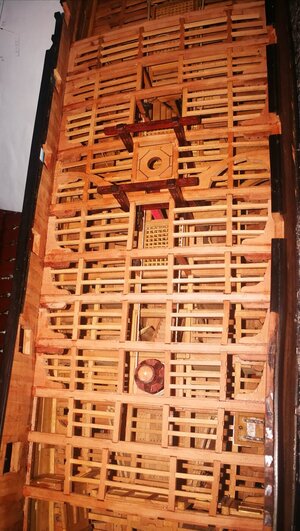
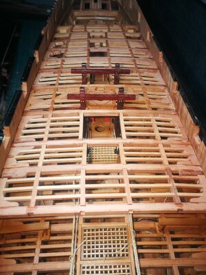
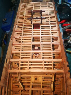
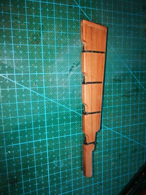
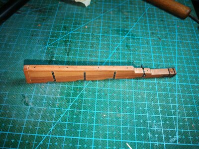
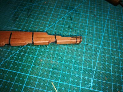
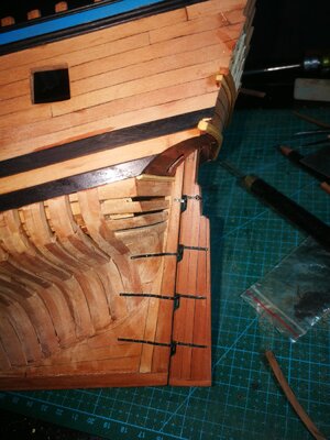
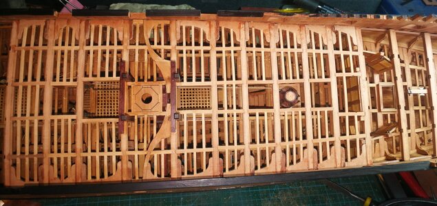
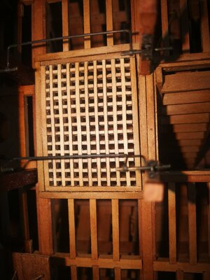
First of all, thank you for your attention. Regarding the grating problem, you may have come to a conclusion too early. He is not a mistake. First of all, he is not finished, and it is not installed in place. These photos are just random during the production process. Photos taken with a mobile phone do not show the final result. The photo below is what it looks like installed, but also not finished, the grating has not been polished. Thanks again for your attention and for the pictures.Really nice work, but sadly the gratings are not correct. Their upper planks must be parallel to the deck planks.
View attachment 315234View attachment 315235
Very good details with f.e. the table- I like it very much
Thank you Uwek, thank you for your continued attention.Very good details with f.e. the table- I like it very much
This is a quality build.
- Joined
- Aug 30, 2020
- Messages
- 639
- Points
- 308

The workmanship and detail is so good, great job.
Great to see your attempt for installing the anchor cable together with a messenger cable for the lifting. It is not often executed but correct for showing an anchor hanging at the bow.
For all other interested in this principle you can find a lot of information here:
https://nautarch.tamu.edu/model/report2/
Looking at your details, maybe some two or three points which come into my mind, which could be added or adjusted if later visible. Pure technical issues
The messenger would no go over the edge of the bitts (red arrows), but would have some pillars or rollers
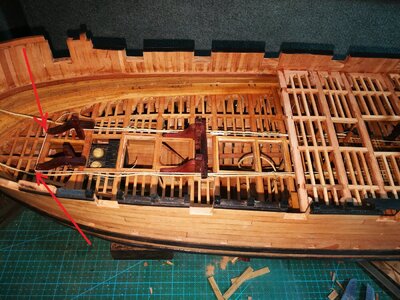
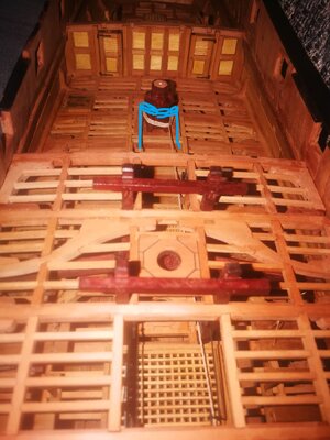
The bolts are looking good (green arrows) but would be flash with the wooden surface - otherwise a rope would be fastly destroyed when pushed over the capstan
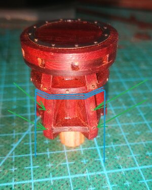
and the messenger would run higher on the capstan because it is under tension and than the loop of the rope will get as small as possible, so it would run over the smallest diameter. In moment it on the biggest diameter close over the deck (blue lines)
Please see these comments as no offense
For all other interested in this principle you can find a lot of information here:
https://nautarch.tamu.edu/model/report2/
Looking at your details, maybe some two or three points which come into my mind, which could be added or adjusted if later visible. Pure technical issues
The messenger would no go over the edge of the bitts (red arrows), but would have some pillars or rollers

The bolts are looking good (green arrows) but would be flash with the wooden surface - otherwise a rope would be fastly destroyed when pushed over the capstan

and the messenger would run higher on the capstan because it is under tension and than the loop of the rope will get as small as possible, so it would run over the smallest diameter. In moment it on the biggest diameter close over the deck (blue lines)

Please see these comments as no offense
Great to see your attempt for installing the anchor cable together with a messenger cable for the lifting. It is not often executed but correct for showing an anchor hanging at the bow.
For all other interested in this principle you can find a lot of information here:
https://nautarch.tamu.edu/model/report2/
Looking at your details, maybe some two or three points which come into my mind, which could be added or adjusted if later visible. Pure technical issues
The messenger would no go over the edge of the bitts (red arrows), but would have some pillars or rollers
View attachment 319214
The bolts are looking good (green arrows) but would be flash with the wooden surface - otherwise a rope would be fastly destroyed when pushed over the capstan
View attachment 319212
and the messenger would run higher on the capstan because it is under tension and than the loop of the rope will get as small as possible, so it would run over the smallest diameter. In moment it on the biggest diameter close over the deck (blue lines)
View attachment 319213
Please see these comments as no offense
Thank you Uwek, I can learn a lot every time I communicate with you.Great to see your attempt for installing the anchor cable together with a messenger cable for the lifting. It is not often executed but correct for showing an anchor hanging at the bow.
For all other interested in this principle you can find a lot of information here:
https://nautarch.tamu.edu/model/report2/
Looking at your details, maybe some two or three points which come into my mind, which could be added or adjusted if later visible. Pure technical issues
The messenger would no go over the edge of the bitts (red arrows), but would have some pillars or rollers
View attachment 319214
The bolts are looking good (green arrows) but would be flash with the wooden surface - otherwise a rope would be fastly destroyed when pushed over the capstan
View attachment 319212
and the messenger would run higher on the capstan because it is under tension and than the loop of the rope will get as small as possible, so it would run over the smallest diameter. In moment it on the biggest diameter close over the deck (blue lines)
View attachment 319213
Please see these comments as no offense
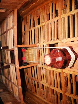
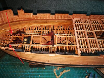 Regarding the position of the courier, this picture is not finished, it's just that the position is just right to straighten the courier for taking pictures, the final position will not be like this, as this picture shows they need a lot of pulleys and rollers, but I probably won't make the pulley because of the scale, just install the roller here, like this.
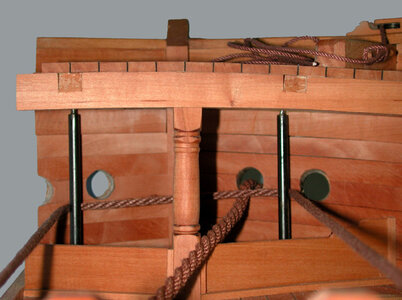
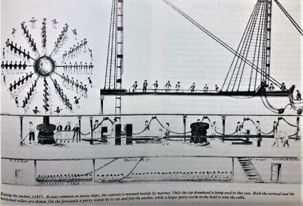 About this picture
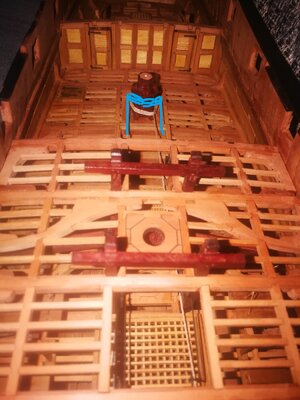
This is not the last position. As mentioned earlier, this position is just right to straighten the courier and facilitate taking pictures. The final position of the messengers is like you said, they will move towards the smallest size under the force.
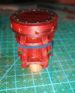
There are nails in this location, and the heads of the nails are no higher than the surface of the wood.
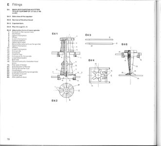
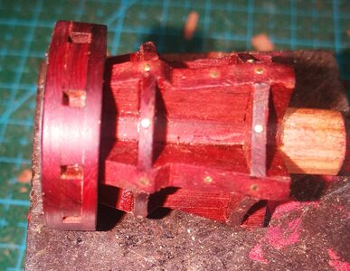
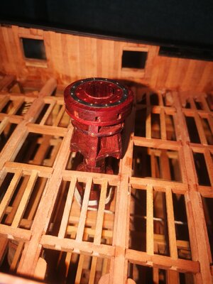
Thanks again Uwek for the comment.
very good work on the rudder - well you try to make it movable with the steering wheel?
Yes Uwek I'll make it move with the steering wheel, just like I used to make another boat.But what confuses me about this boat is that the rudder is turned too smallvery good work on the rudder - well you try to make it movable with the steering wheel?
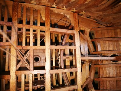
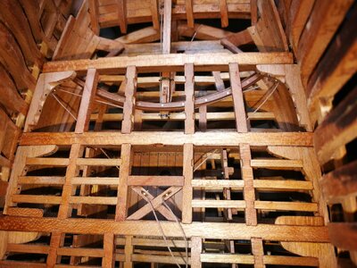 But what confuses me about this boat is that the rudder will turn very little
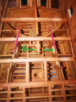
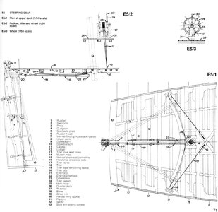
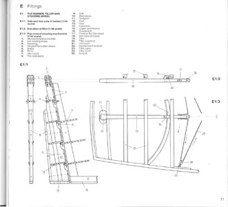
The length of the tiller is made according to the picture, there is no mistake, but I am confused about the steering mechanism of the rudder shown in this picture, and it feels a little unreasonableI understand what you mean, with the too small place for the tiller.
Is the tiller in the correct length - often it is not much longer up to the running rail beam (the half round)
View attachment 320302 View attachment 320303
- Joined
- Aug 14, 2018
- Messages
- 471
- Points
- 323

Hello Wang. I have been looking at your problem with the range of movement of the rudder. It is hard to tell from your pictures exactly how far in degrees the tiller will move to either side before fouling. In reality a frigate such as Blandford the tiller should swing about 30 degrees either way to be 'full over' at that point the chamfer on the inside of the rudder will be flat on the stern post. Can you measure the angle to see how close you are getting to 30 degrees?The length of the tiller is made according to the picture, there is no mistake, but I am confused about the steering mechanism of the rudder shown in this picture, and it feels a little unreasonableView attachment 320537
First of all, thank you very much for your attention, thank you for providing the rotation angle data of the rudder. From this picture, you can probably tell that there will be no 30 degrees.Hello Wang. I have been looking at your problem with the range of movement of the rudder. It is hard to tell from your pictures exactly how far in degrees the tiller will move to either side before fouling. In reality a frigate such as Blandford the tiller should swing about 30 degrees either way to be 'full over' at that point the chamfer on the inside of the rudder will be flat on the stern post. Can you measure the angle to see how close you are getting to 30 degrees?
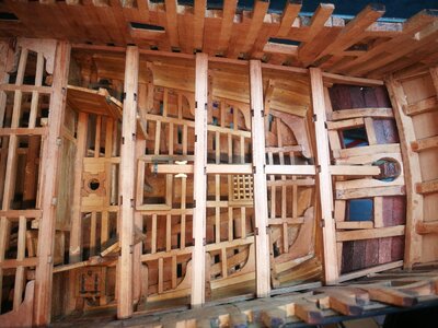
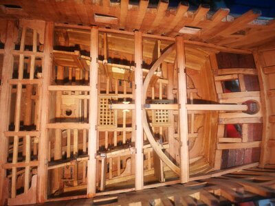
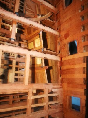
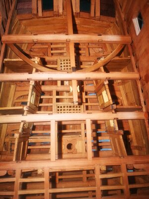
I made the cabin and interior based on these pictures。
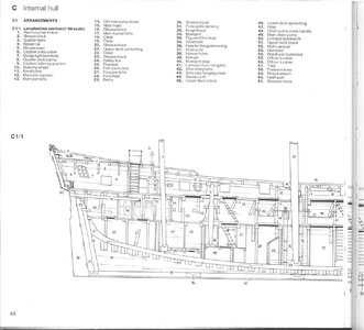
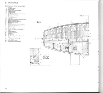
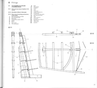
Since the angle on the model is not easy to measure, I directly made a simulation picture on the last picture, and the scale of the picture is 1/48。
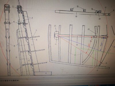
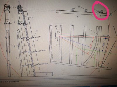
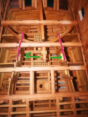
The green line is the location of the bulkhead inside the ship. It can be seen that the turning angle of the rudder is less than 30 degrees, which will be blocked by the bulkhead, and when the front end of the tiller touches the bulkhead, the turning angle of the rudder is only 18 degrees, as shown by the blue line in the figure. That is, the maximum turning angle of the rudder is only 18 degrees, so I think it is unimaginable that the rudder of a real ship has such a small turning angle in reality。
- Joined
- Aug 14, 2018
- Messages
- 471
- Points
- 323

Hello Wang ' you are correct 18 degrees is far too small a turning range. I can only suggest that the tiller had been drawn incorrectly and is not as long as suggested. To support this theory look at your red line showing 30 degrees it is right out as far as the block and I would think that very impractical. I am also building HMS Blandford and in time will install a shortened tiller than the one shown in the Anatomy of the Ship book. I love your log, you are doing a great job and I will be keen to see what you decide to do with the steering gear. Thank you for publishing your work. JJ.First of all, thank you very much for your attention, thank you for providing the rotation angle data of the rudder. From this picture, you can probably tell that there will be no 30 degrees.View attachment 320659
I made the cabin and interior based on these pictures。
View attachment 320661View attachment 320662View attachment 320668
Since the angle on the model is not easy to measure, I directly made a simulation picture on the last picture, and the scale of the picture is 1/48。View attachment 320669
The green line is the location of the bulkhead inside the ship. It can be seen that the turning angle of the rudder is less than 30 degrees, which will be blocked by the bulkhead, and when the front end of the tiller touches the bulkhead, the turning angle of the rudder is only 18 degrees, as shown by the blue line in the figure. That is, the maximum turning angle of the rudder is only 18 degrees, so I think it is unimaginable that the rudder of a real ship has such a small turning angle in reality。
Glad you are also making this kit, but need to clarify, the material for the inner structure such as the tiller and the cabin is not included in the kit, these are all made by myself from the plan, and the length of not only the tiller in the book There is a problem. Its entire steering mechanism is unreasonable. It can be seen from the red circle in the figure that the top end of the arc positioning block on the tiller is almost on the same level as the top end of the beam, which is unreasonable. Yes, because a short small beam will be installed between the two beams, and the tiller cannot move after the small beam is installed, so I think the rudder turning mechanism shown in the bottom picture is reasonable. In addition, the length of the tiller should not be too short. If the tiller is too short, it will require a lot of force when turning the rudder.Hello Wang ' you are correct 18 degrees is far too small a turning range. I can only suggest that the tiller had been drawn incorrectly and is not as long as suggested. To support this theory look at your red line showing 30 degrees it is right out as far as the block and I would think that very impractical. I am also building HMS Blandford and in time will install a shortened tiller than the one shown in the Anatomy of the Ship book. I love your log, you are doing a great job and I will be keen to see what you decide to do with the steering gear. Thank you for publishing your work. JJ.
