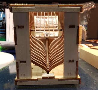
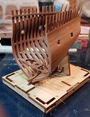
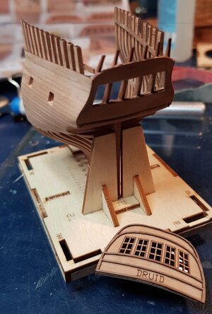
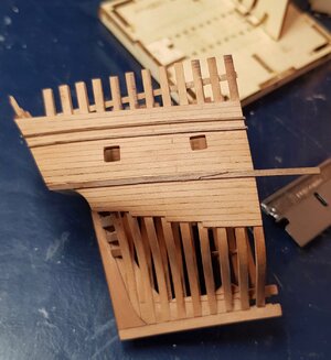
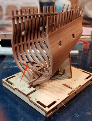
HMS Druid 1776 (x 2) by Unicorn Model, 1/128 [COMPLETED BUILD]

Joined
Aug 2, 2018
Messages
458
Points
278

Location
Sydney, Australia
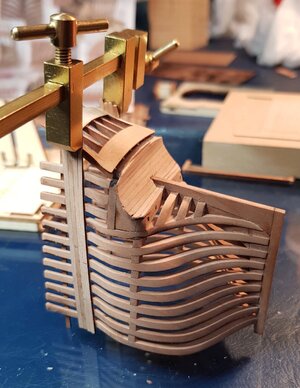
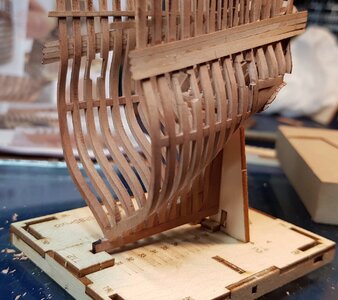
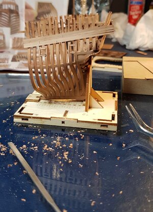
Today I began the Unicorn Model's miniature kits of the HMS Druid cross sections.
The first is the stern cross section and the second kit is the middle cross section. The stern cross section came out about a year before the middle cross section.
I have had both for a few months now and always planned to build them simultaneously so that the final look is similar as I plan to display them in line in the same display case. Off course the final look will also be dependent on the wood supplied in each kit and since they were manufactured at least a year apart I'm not holding my breath on getting an identical finish for both. The kit states that the wood is pear.
So now to the photos:
Here are both kits- One opened already, the other one in it's plastic shrink wrapping between two plywood boards.
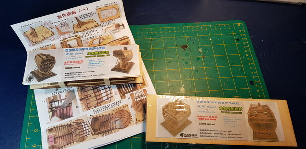
20201229_190745.jpg
By the way to get an idea of scale my dirty cutting board has 1" squares in the middle for those not using metric.

A closer look at the stern section label
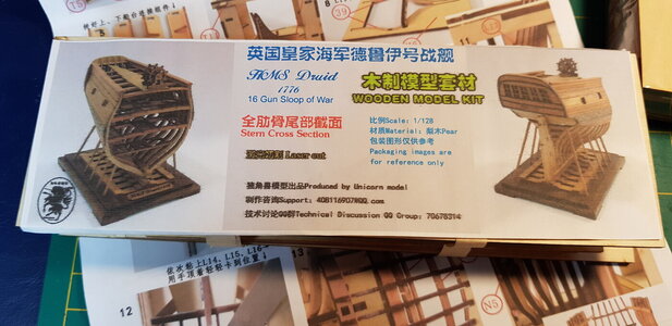
20201229_190803.jpg

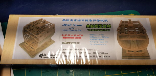
...and the mid section packaging

20201229_190756.jpg

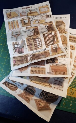
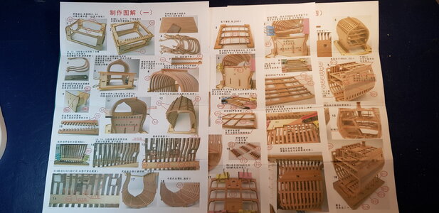
Instructions for both are on four A4 sheets of paper, printed single sided, all easy to follow photos but only in Chinese.
Having a camera translator App on your phone like Google Translate makes easy work of reading these instructions.
fullsizeoutput_22.jpeg20201229_210740.jpg

The Kit's contents
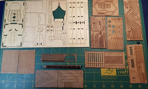
First the stern Section:
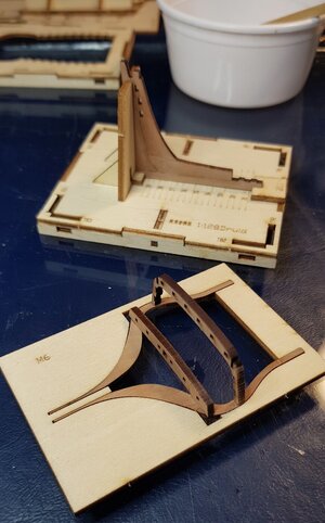
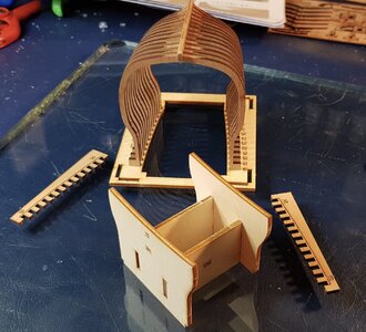
The kit's building jig/berth are the light coloured plywood pieces in the top left of the photo.
fullsizeoutput_24.jpeg

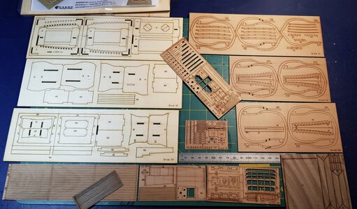
The contents of the Mid Section kit:

fullsizeoutput_20.jpeg

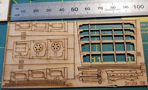
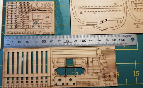
Some close up details:

fullsizeoutput_25.jpeg

Some parts like A01, A02 and A03 are less than 1 mm wide and quite long with disproportionately large tabs to keep them attached so I am fairly hesitant in cutting these pieces away from the boards. At least the grain is going in the right direction to cut them away but we'll see- any tips by anyone having done anything similar with delicate pieces is definitely welcomed.
fullsizeoutput_26.jpeg

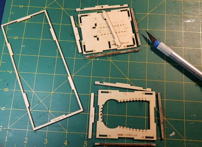
This is just a preview of the first parts of the building jig/berth being sanded and prepared for glueing.
fullsizeoutput_1c.jpeg
 
Last edited:
A Chinese kit with full-color, detailed, visual instructions that have no need to be accompanied by a poor translation. All kits designed to be sold for an international market should include this. Woody Joe kits from Japan set the standard for this type of manual.
 
Following this thread with interest.

As I have the bigger full Druid version its been months that is in my mind buying these two guys as a sort of a "Druid set", independently that the scales are different.

I have seen another built, but I am sure yours will be "the one to follow" to finally decide what I will do.

Thank you for all the details you have already posted.

Best
Daniel
 
A Chinese kit with full-color, detailed, visual instructions that have no need to be accompanied by a poor translation. All kits designed to be sold for an international market should include this. Woody Joe kits from Japan set the standard for this type of manual.
The colour pictorial instructions are very good however you will still need to understand and translate the comments.
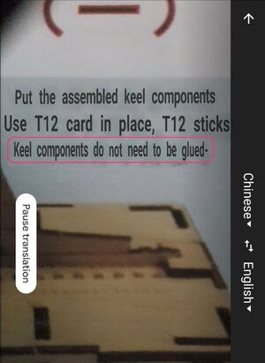
For instance in the 3rd instruction panel there are directions to not use glue when positioning the keel on the jig when using translator app.
Translator.jpg
It seems obvious at this stage but later it could become essential to be aware of this type of information.
A great improvement to the instructions would be to use universal symbols such as:
Screen Shot 2020-12-30 at 3.12.07 pm.png
 
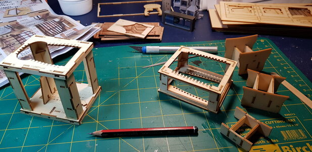
The building berths and some alignment jigs have been assembled and glued in the places that are required, most of the mid section jigs are not glued as they need to be taken apart when surrounded by the model according to the instructions- but I will glue them at the right time of the build if needed.
So far there has been only very minimal sanding required, and the pieces fit together very tight, square and accurate.

The stern section building berth is on the left, mid section berth and alignment jigs are on the right.
20210101_215305.jpg
 
Last edited:
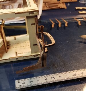
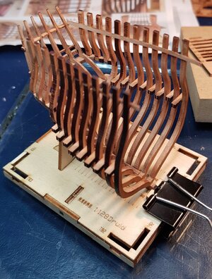
The first pieces of the stern section were cut away from the boards and so the ship construction begins.
The building jig can be separated and at no point are the parts of the model glued to the build jig.
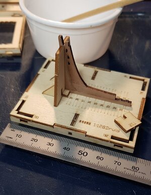
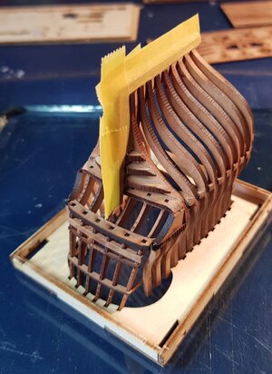
Stern and keel are glued flat on glass plate and placed in the jig without the jig top or its uprights.

After the stern post and keel fits snug the loose piece T12 (See this piece on top of the jig on the right) is glued into place holding the model tight but not glued.
fullsizeoutput_2d.jpeg

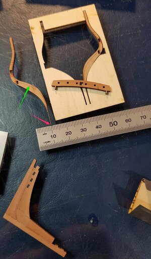
Next Frame 39 must go into a special (one off) jig solely for lining up frame 39 with the transom cross frames.
But first the we need to file the frame to the marked line (green arrow). Lot's of care needs to be taken here- if you hold the frame incorrectly while filing and sanding it could break in the ultra delicate areas such as the red circle.
Notice the thickness (or thinness) of the frame at the bottom.
Frame 39.jpg

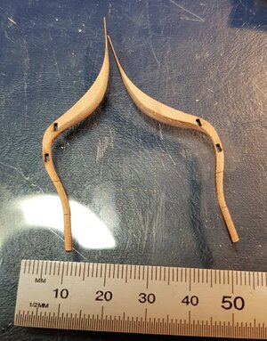
Frames sanded and ready for next step. I left a minuscule amount still to be sanded for final fairing of the inside of hull.
fullsizeoutput_2f.jpeg

Pieces glued. It's very hard to make mistakes when you have jigs like these and the pieces fit together nicely.
fullsizeoutput_30.jpeg

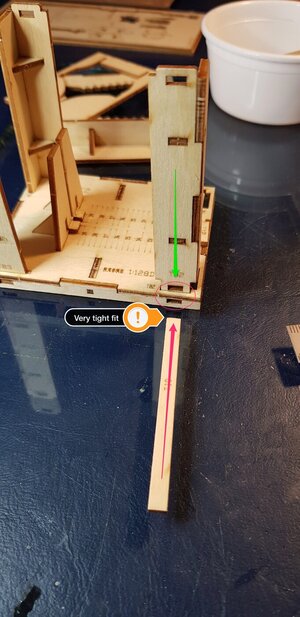
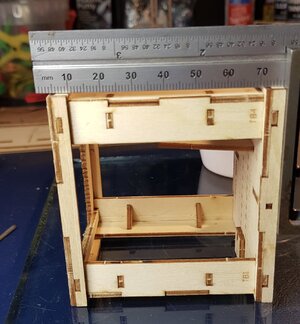
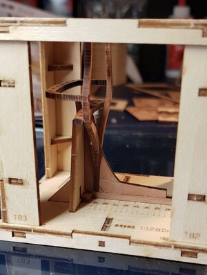
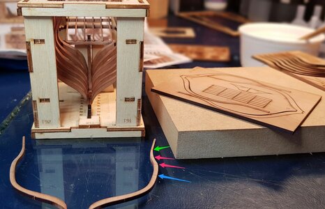
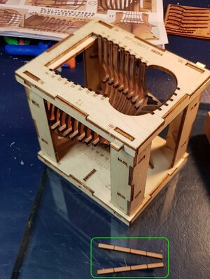
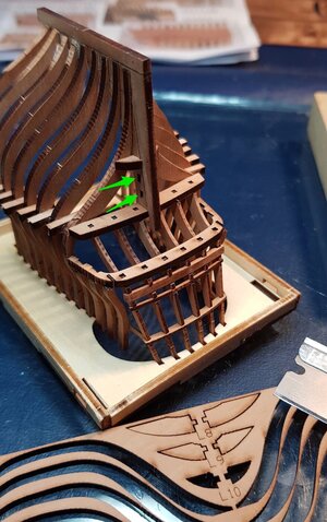
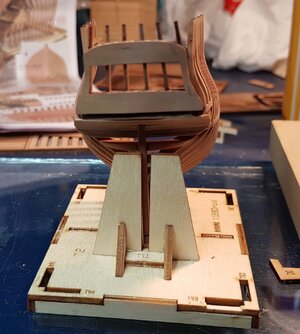
Now the building berth must be completely built. First the upright column's slots must be fully inserted into the clearly numbered slots in the jig (Green Arrow)
I then found that the holding key pieces were too tight so I slightly sanded over the leading edges, after that the key slotted inside and through to the other side nice and tight.
connector.jpg

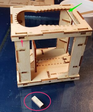
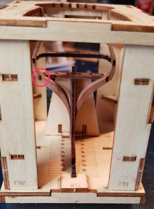
The top rear keys (red circle) are 2 short pieces and inserted in their slots (red arrow) if they were a full length key like the other three it would interfere with the transom parts in the middle of the rear of the jig.
You can see the upper forward key (green arrow) does not interfere with the most forward frame in the jig.Small.jpg

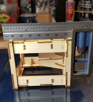
Checking for square.
fullsizeoutput_32.jpegfullsizeoutput_33.jpeg

Frame 39 and transom cross pieces dry fitted to the stern post.
fullsizeoutput_35.jpeg

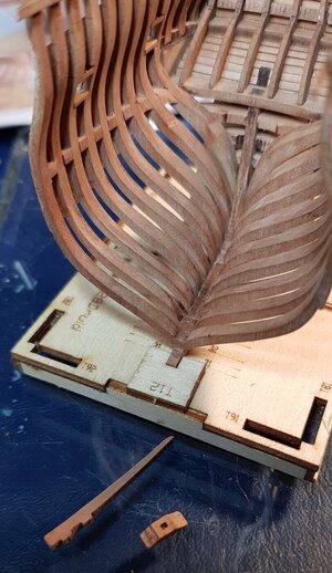
Here you will notice the break just where the lower left slot is (red circle). It was a silly mistake- I was careful to handle the pieces while I was working on them however I held this frame in my left hand while I went to do something with my right hand- then I felt the 'snap'.
Luckily the build jig corrected this while slotting in and glueing the transom pieces without any issues.
break.jpg

Frame lines up with markings on the building jig base.
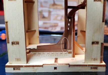
I pencilled in line (White circle) near the bottom of frame 39, the area below the line was not glued as at a later date it will be cut away to be inline with the line on the keel/stern post.
Cut line.jpg

The model taken out of the build jig.
Transom upright frames are in the background sanded and prepped for gluing.
fullsizeoutput_36.jpeg

Installing with ease.
fullsizeoutput_37.jpeg

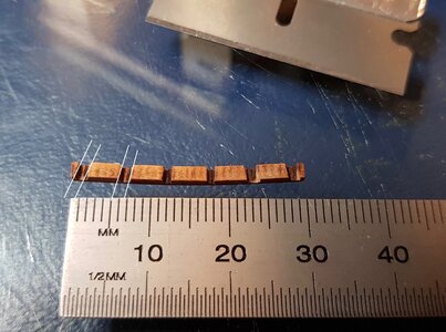
The lower of the three transom horizontal braces needs to have some minor work:
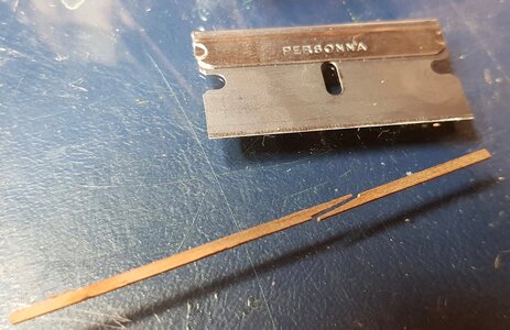
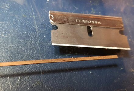
Because the two outer transom uprights are at an angle the two outer slots on each end needed to be cut at angles (white lines) into the insides of the slots with a very sharp brand new razor.
This needs to be done by taking very thin slices until the fit is right.
I wouldn't recommend trying to cut in one go or even file the outer slots as there is not much wood mass to support the cutting or filing pressure.
angle.jpg

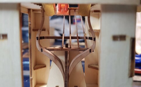
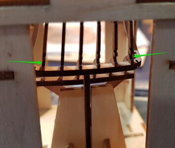
This is where the transom's lower horizontal brace will go.
slots.jpg

And after it has been glued.
fullsizeoutput_3b.jpeg

I will probably work on glueing in the other two transom cross-pieces above this one to strengthen the delicate uprights them move on to the mid section kit.
 
Last edited:
Very well defined build log, with lots of explanations and outlines, a fine example for many of us. Many thanks, John! The parts are so tinny...
 
So onto the mid section kit.

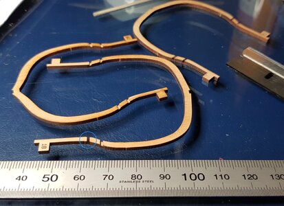
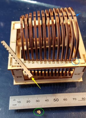
Before glueing the ends of the ship frames into the build jig there were some pre-lasered slivers of fine wood (Blue Circle) that needed to be cleaned out to form slots which would allow the gunport frame to be inserted later.
Frame.jpg

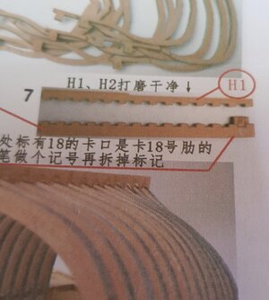
The keel has a numbered tab on one end that indicates how to align the keel correctly. (Frame 18)
fullsizeoutput_43.jpeg
After inserting all the frames in their respective marked slots in the build jig I marked the keel with frame '18' in pencil (yellow Arrow) before removing the tab from the keel so as to not get mixed up with the wrong end.
Number 18.jpg
Here you can also see how I removed the majority of the laser char close to the keel so it becomes easier to sand the frames fair later.

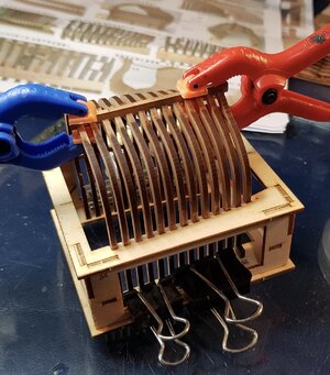
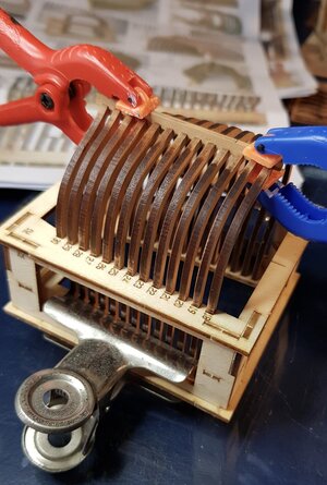
Next, the keel is glued on to the frame at the same time as the frames are glued into the jig.
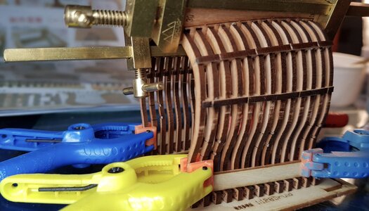
Undiluted glue is applied to the keel and once the keel is fixed I clamp the frames down with the convenient tabs and use diluted glue from the underside of the jig.
fullsizeoutput_47.jpegfullsizeoutput_48.jpeg

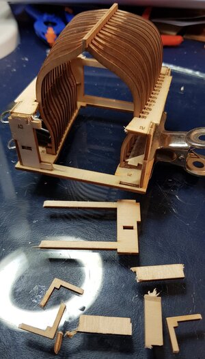
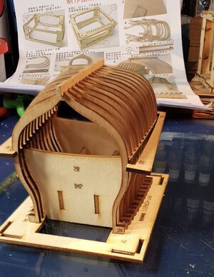
Once the glue is dry, the top part of the build jig and its uprights can be removed as they're no longer needed.
fullsizeoutput_4a.jpeg

Now the blocks between the frames (sorry, I don't know their name) are glued in. This is the easiest and most convenient system I have seen for this.
But first a jig template must be built to align the blocks correctly, the jig clearly states where to align with the correct numbered frame.
fullsizeoutput_4c.jpeg

Block piece is inserted between the frames and glued- you can see part of the block's insert breaks away and can be discarded when the glue dries.
fullsizeoutput_50.jpeg

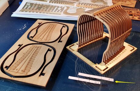
For the next two rows of blocks the instructions say to space equally between the keel and the newly inserted row of blocks- for this I use paper strips, divide by three spaces to get two evenly spaced marks, then I write on the paper the correct frame number and just for good measure I mark a 'K' so both sides of the frames are measured down from the keel.
You can see the pencil marks on the end frame.
Paper.jpg

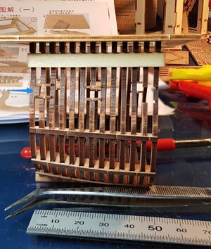
The two other rows of blocks are glued into both sides of the frame. Also a plywood spacer strip is glued to the bottom (top) of every frame ready for the next stage.
fullsizeoutput_54.jpeg

Gunport framing.
The glued plywood strip from the previous image is designed to keep the remaining frame perfectly aligned after cutting out a piece of frame.
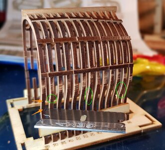
Here you can see 3 ship's frames on each side that are pre-cut (green circles) needing to remove part of the frame which will be the gunport opening. The previously cut out notches (orange arrow) will be used to receive one side of the horizontal gunport frame pieces.
On the back/left side you can see the frame cut and the plywood strip working to keep the loose frame perfectly aligned (a bit out of focus)
Notches.jpg

A quick note on being very careful with the delicate parts.
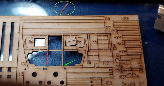
On this board I needed to remove parts H6 for the upper/lower gunport frames so I decided to give the whole side of the board a quick sanding over to remove some of the laser over-char. Bad mistake: the 1st pass with a flat sanding block removed this thin piece (yellow circle) and broke away one end of another piece which was glued back (green arrow)
broken.jpg

Gunport framing begins.
Here you can see the 3 stages, from the left:
-Completed gunport frame with upright piece inserted (blue arrow)
-Top and bottom pieces of the gunport frame only- notice how one side of the horizontal pieces is inserted into the ship's frame slots, the other side will be supported by the upright piece (not yet in place).
-The last gunport has the frame cut and notches ready to receive the gunport pieces.
upright.jpg
No need to sand as the clean part of the wood will be on show and the charred part of the wood will be sanded later when fairing the side of the ship. This process is incredibly simple and only takes a couple of minutes for each gunport.

Note: each gunport vertical piece is slightly different and fits perfectly into the correct gunport only.
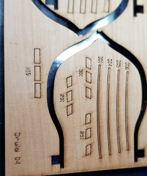
Part 301 is for the gunport on one side, part 251 is for the middle gunport and part 201 is for the other side- with one each to spare incase it gets sucked into the shipbuilder's blackhole.
fullsizeoutput_56.jpeg

Gunport framing completed
fullsizeoutput_5c.jpeg

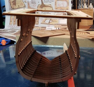
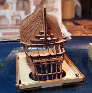
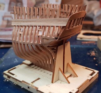
So this is how the mid section looks now, ready for internal sanding. The decks will be next, but first we will return to the stern section.
fullsizeoutput_5f.jpeg
 
Last edited:
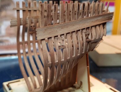
So moving on to the stern section of this very fun build; the remaining frames need to be glued into place.

Here you can see the frames were faired to the marked lines both on the half frames and the only 2 full frames.
After sanding I put them back in the cutout boards to maintain some order with these small parts. I also put them on a piece of MDF so I could move them around since all the frames were loose.
Fairing.jpg

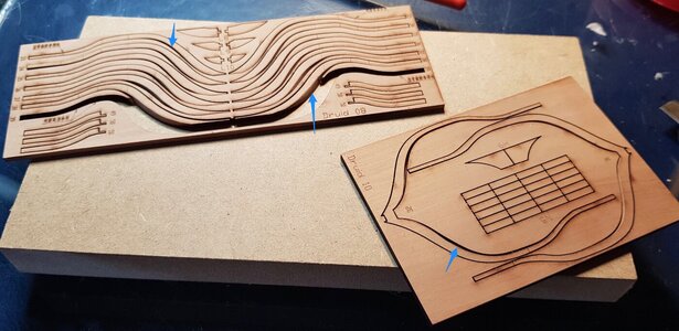
Here are the two last half frames ready to be glued in place. You will notice that they come with several marks for later use:
Blue arrow are for the location of the blocks, Red arrows the top and bottom lines of the gunport, Green arrow is where a temporary plank will be glued to keep the top of the frames aligned.
Markings.jpg

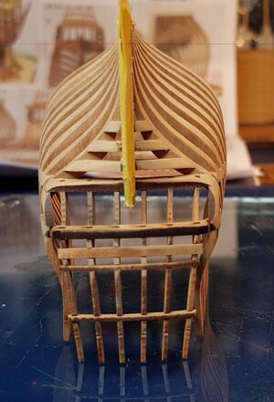
The stern section fully framed.
20210108_172254.jpg

The blocks between the frame are added one by one. No sanding is needed as the charred sides will be glued against the frame and the clean sides will be displayed. You can see below how easy they were to snap off and glue. Just a few minutes is needed to align to the marked lines on the frames.
Blocks.jpg

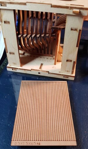
Ship's planking comes pre-cut, two planks will be used on the inside of the top frames.
20210108_210617.jpg
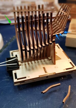
The top and sides of the build jig is dismantled

The green arrow shows the temporary plank in place so that the filling timbers (bottom) can be installed into the slots (blue arrows)
Slots.jpg

Filling timbers glued onto both sides.
20210108_230530.jpg

The wing transom pieces are removed from their board and glued in to the perfectly fitting slots marked with the green arrows.
Tran frames.jpg

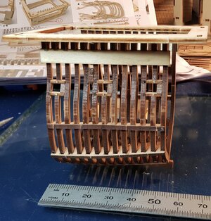
Apart from the gunport frames all the other framing is complete.
20210108_235134.jpg

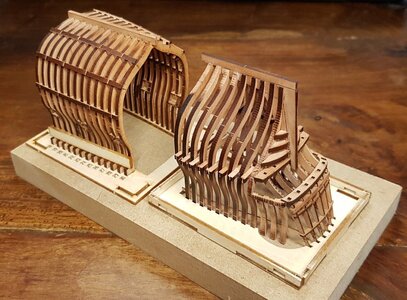
This is how both sections look at the moment.
20210109_105206.jpg
Lots of sanding to come.
 
Last edited:
Hi John , I also have the same set. Tks for string this log. looks a lot of fun.
Both kits are a lot of fun. It's nice when everything just fits perfectly in place.
So far I have been able see how the kits have evolved from the stern section (which came out first) to the mid section. There are definite improvements and upgrades made from one kit to the next.
 
So after a few days away on a summer break with the family I got back into the stern section again.
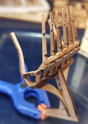
The mid section model is glued securely into the build jig so my real concern was the fragile state of the stern section that was not held in any jig securely. I wanted to at least get the external hull planking on so as to make it more stable.
So before any planking could begin i needed to mask off the keel to avoid sanding scratches, then I proceeded to sand the frames fair.
20210110_155900.jpg

Nearly done.
20210113_205032.jpg

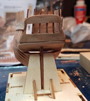
Before planking the sides of the hull I needed to plank the rear transom and also add the transom gallery piece.
On the left you can see the jig used to shape the curve of the transom gallery piece. To the right are the laser cut planks, there is almost no sanding required as the laser char can (may) serve as caulking.
20210113_220559.jpg

This isn't a good photo but it gives an indication of how the hull fairing and transom gallery piece will align.
20210114_213627.jpg

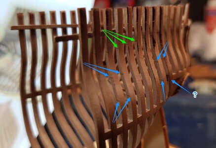
Because the two gunports on each side need to be shaped into the frames before we can complete all the hull planking. It is required that only the top 4 planks on each side are glued in place before working on the gunports. This keeps the top part of the fragile framing a lot more sturdy.
Below are the marks on each frame for aligning the top plank (Green arrows) and the marks where the gun ports are to be carved out (Blue arrows). The lower-aft frame has no making as the slot for the transom frame is located in that position- or perhaps the line was there previously but lost.
Markings.jpg

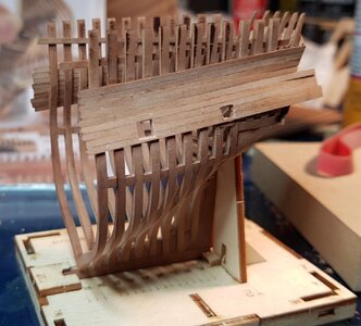
Upper four frames on each side are glued into place. I tried cutting butt joints into the planks prior to gluing onto the model.20210114_231128.jpg

Carving out the gun ports half way into each frame.
20210116_222922.jpg

Upper and lower frame pieces added to the gunports.
20210116_222847.jpg
20210116_224719.jpg

Here the transom planking and gunport frames are sanded fair ready to continue the planking down the hull sides
20210117_194058.jpg
20210117_194108.jpg

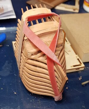
Getting creative when clamping down the aft end of the planks around the transom's curved shapes.
20210118_222042.jpg

Planks cover the gunports; I stopped here because this is as far as the clamps can reach the middle and aft of the planks from the top.
Decided to file out the gunport openings.
20210117_232215.jpg

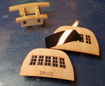
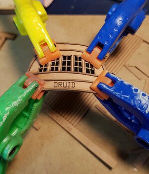
Using an old floppy disc to simulate the windows. This scale allows the disc to give a good effect.
20210120_224448.jpg

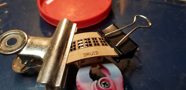
Disc glued in place between the two water soaked plywood pieces and placed in the curved transom jig mentioned previously.
20210120_225559.jpg

Last plank added to the hull sides as mentioned in the instructions.
20210123_203453.jpg

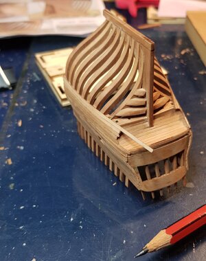
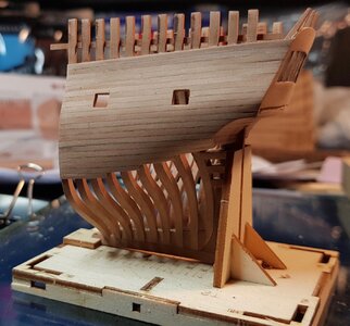
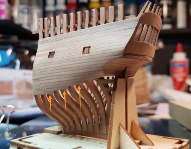
I inserted another 3 partial planks to simulate semi-built ship section.
20210124_223855.jpg

Shown better here with the three orange arrows:
Additional planks.jpg

Very fragile, single-piece transom decoration glued into place.
20210125_223602.jpg

The keelson and mast step ready to be glued in place- the instructions say to do this step right at the end but it would be difficult to access the aft of the keelson when the decks are in place.
20210125_223642.jpg

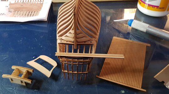
Lower deck glued in place, a considerable amount of fairing the rear of this single-piece deck is required to make it fit nicely on the frames. There was also an alignment jig included with the kit that I did not photograph. Not my best work, but it will do.
20210126_172113.jpg

I really should be moving onto the mid section kit at this stage but I was really enjoying this stern section kit.
Rear transom 'wall' ready to go up. But first the wales and other strakes need to be glued and faired into place.
20210126_172153.jpg

There are 2 thin strips and 4 wider wales to be added to each side of the hull.
Here I am testing a scarph joint on the wider wale piece- it's being applied to the side that will not be displayed in case it doesn't work.
20210126_191359.jpg
20210126_191425.jpg

...and finally glued onto the model.
20210126_224352.jpg
How does it look?
I'm still not sure about this scarph joint.
 
Last edited:
Great progress on a very small scale, John. Because of your quality work, I like it more and more. :)
Thanks Jim, you will enjoy this as a side project.
To be honest I chose to build these kits prior to the Trident Alert kit so that it can 'train' me to only accept tighter tolerances when putting joinery together on larger scales, and there is a lot of joinery in the Alert's framing and deck structures. The smallest error at the scale of this Druid is magnified tremendously so it's good to learn to try to get it right.
Also, it has trained me to use PVA sparingly and cleanup glue squeeze-out about 20 minutes after applying when the glue is not yet hard but no longer wet (gummy consistency) and can be removed easily without staining.

As you can see in the photo where I added the first deck I used CA glue for the first and only time and regretted it immediately. I had to use it because the deck kept moving and sliding down the frames and needed something to hold fast. The CA shiny stain is small but is fairly prominent at this scale.
CA glue.jpg
This will be scraped away, but it is definitely a lesson learnt.
 
Last edited:
Looks very high quality work.

Now if they made a bow section to complete the set you would have a grand project.
Hi Kurt, thank you.

I purposely ordered a longer acrylic display box to cater for the (hopefully) upcoming bow section.
I will be making a display case for these kits at the end of this log so you will see what I mean.
 
Back
Top