-

Win a Free Custom Engraved Brass Coin!!!
As a way to introduce our brass coins to the community, we will raffle off a free coin during the month of August. Follow link ABOVE for instructions for entering.
-

PRE-ORDER SHIPS IN SCALE TODAY!
The beloved Ships in Scale Magazine is back and charting a new course for 2026!
Discover new skills, new techniques, and new inspirations in every issue.
NOTE THAT OUR FIRST ISSUE WILL BE JAN/FEB 2026
You are using an out of date browser. It may not display this or other websites correctly.
You should upgrade or use an alternative browser.
You should upgrade or use an alternative browser.
HMS Druid P.O.F. - Unicorn Models by Donnie [COMPLETED BUILD]
Thanks guys for the feedback and the 'get wells'. Well, it is my own fault. I should have been taking breaks from leaning over into the thing (drill press - I converted my Drill Press into a spindle sander) - therefore the way the machine is oriented, makes me lean into the sanding disk so that I can see what exactly I am doing.
I am only 63 --- I should not be having these problems -- right?
I am only 63 ---
I also hope that you will be well soon. Guys our age, I'am 65, get a little niggle now and then. That won't stop you from being diligent and enjoying your work.
Hope you get well soon Donnie
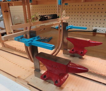
My back is still in trouble, but I could not help it as I thought this would be a very low impact thing to do and I did not do all of this in one sitting. The image might not make that much sense. I know it is or seems a rather elaborate setup, but I wanted to be sure that my center reference frames were as much dead on as I could get. Errors always accumulate no matter how careful.
Here are my thoughts:
I did not want to start the process of installing FRAMES at the bow as I was concerned that the propagation or (accumulation) build-up of errors would occur as I reached the end of the Stern.

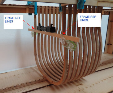
You will see from this last image (below) of the Machinist Square that the BOTTOM TIP is at REFERENCE LINE #18.

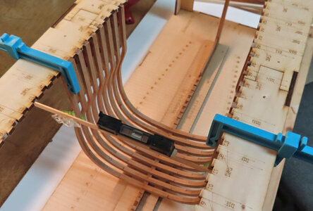
Therefore, I decided to make TWO CENTER FRAMES become the reference. One will be the reference going towards the Bow and the other will be the reference going towards the Stern. This way, perhaps I might avoid any build-up of error as the frames are inserted and glued.
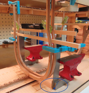
The square rod horizontal is a 6mm rod that is the amount of separation between the frames. The tip bottoms of the machinist squares are not what they seem. From the images, it looks like the squares are sitting midway of the reference points on the Lower Base Plate. But the location of the machinist squares is right on the mark and therefore sets the frame 90° verticle. I also measured the frame from side to side to make sure the outside edges are also the same on each side. From the Frame, outer EDGE to the JIG SIDE measures 30mm exact on each side. So, I know that the frame is sitting square in that dimension as well.
You will see from the last image of the Machinist Square that the TIP is at REFERENCE LINE #18.

Now I have to go back and lay down -
Here are my thoughts:
I did not want to start the process of installing FRAMES at the bow as I was concerned that the propagation or (accumulation) build-up of errors would occur as I reached the end of the Stern.

You will see from this last image (below) of the Machinist Square that the BOTTOM TIP is at REFERENCE LINE #18.

Therefore, I decided to make TWO CENTER FRAMES become the reference. One will be the reference going towards the Bow and the other will be the reference going towards the Stern. This way, perhaps I might avoid any build-up of error as the frames are inserted and glued.
The square rod horizontal is a 6mm rod that is the amount of separation between the frames. The tip bottoms of the machinist squares are not what they seem. From the images, it looks like the squares are sitting midway of the reference points on the Lower Base Plate. But the location of the machinist squares is right on the mark and therefore sets the frame 90° verticle. I also measured the frame from side to side to make sure the outside edges are also the same on each side. From the Frame, outer EDGE to the JIG SIDE measures 30mm exact on each side. So, I know that the frame is sitting square in that dimension as well.
You will see from the last image of the Machinist Square that the TIP is at REFERENCE LINE #18.
Now I have to go back and lay down -
Wow - you are making it really very accurate - but you are right to do so
Thank you Uwe and others. These two are just the reference frames, the others will not require so much attention.
Revisited the Doctor again this morning - near unbearable pain again. X-Ray and possible MRI. Gave me pain meds to accommodate the steroids this time.
Revisited the Doctor again this morning - near unbearable pain again. X-Ray and possible MRI. Gave me pain meds to accommodate the steroids this time.
Kurt Konrath
Kurt Konrath
Get feeling better and keep up the great work.
Yes Donnie, that's it, simple yet brilliant. I really like the way you work.
You're back! Glad you are feeling well enough to glue up frames. Tidy work.
Hi Donnie, great work, it is all well worth it.
Your work looks very meticulous, just perfect.
Your work looks very meticulous, just perfect.
EDIT: ALL OF THE SPACERS WILL BE REMOVED. I INSTALLED THEM IN THE WRONG LOCATION. I AM COVERING UP THE LASER ENGRAVED REFERENCE MARKS FOR THE BEAM STRUCTURE. THIS POSES A BIG PROBLEM. I WILL HAVE TO DRY FIT THE BEAMS ON THE LOWER DECK AND THEN REINSTALL THE SPACERS LATER. THIS IS VERY BAD NEWS AND IS VERY DISCOURAGING TO ME.
Thank you all for the kind words about getting well. As a side note, I am now 'not' in any pain. I have started a treatment plan with a Chiropractor. The spine X-rays show some curvature and one main vertebra that is twisted out of alignment and that is being corrected now.
So, I feel it some better to be able to mount many more frames now and in the process, it is time to install some 6mm spacers. This is quite a boring task, but must be done to secure the frames to make sure they do not move during the rest of the build. The kit comes with 6mm x6mm spacers that are laser cut, but because of the angle that the laser produces, the spacers the kit provides are not good, so I have some soft basswood laying around that happens to be 6mm square.
Last edited:
G'day Donnie I'm glad to hear that you are getting better and that things are starting to improve for you, its nice to see you back in the ship yard again,
best regards john.
best regards john.
So pleased to see you back at it. Go easy!
At my appointment today - the Doc asked me if I was working on my ship - he knows what I do for a hobby - ( yes, I have been working on it, but I did not answer him) HA - he told me if I was --- DO NOT do that right now -- oh well --- no more working in the yard for a little while longer !!! 
At my treatment today, the doc told me DO NOT work on your model yet.
He knows a lot about my hobby as I have shared w him. Today, he said not yet. I have some more healing and need to wait.
He knows a lot about my hobby as I have shared w him. Today, he said not yet. I have some more healing and need to wait.
Get better soon, Donnie. 
EDIT: ALL OF THE SPACERS WILL BE REMOVED. I INSTALLED THEM IN THE WRONG LOCATION. I AM COVERING UP THE LASER ENGRAVED REFERENCE MARKS FOR THE BEAM STRUCTURE. THIS POSES A BIG PROBLEM. I WILL HAVE TO DRY FIT THE BEAMS ON THE LOWER DECK AND THEN REINSTALL THE SPACERS LATER. THIS IS VERY BAD NEWS AND IS VERY DISCOURAGING TO ME.
- Joined
- Dec 1, 2016
- Messages
- 6,383
- Points
- 728

Donnie i like the way you are working the hull. It is a cautionary story to all builders. Never ever start at one end and work you way to the other end. I learned that the hard way. no matter if your framing a hull or deck set up a reference frames or set beams in a deck at the location of hatches or masts and fill in between them.
i will always set the midship frame up and the last whole frame forward and aft. Then set up a frame between midship and those last whole frames. Then i will fill in the rest of the frames.
i feel your pain arthritis in one knee has put limits on what i can and can no longer do. Arthritis in my hands some days is painful. The times comes when we have to come to terms with aging and pain.


