• Win a Free Custom Engraved Brass Coin!!!
    As a way to introduce our brass coins to the community, we will raffle off a free coin during the month of August. Follow link ABOVE for instructions for entering.

HMS Enterprise 1775 1/96 - First build log

OK Allan I will try it on a test piece. I need more guidance though. I imagine the correct size would result in an attractive 'slender' appearance, but I'm not clear about the rate of taper e.g. If I do so, how 'thick' should the upper and lower sills be for the gunports? Upper sills around midship might be very thin.
The contract that you have gives the moulded dimensions at each end of the floors and most of the futtocks so you can see the amount of narrowing each frame does in the in and out direction, It is gradual unlike the stepped reduction in the sided direction. The sills will be the same dimension as the in and out/'moulded dimension of the frame at the point where the sills are set in place. I hope this makes some sense, because as I read it back, I am not so sure.

Allan
Thanks Allan,

I get it. Time to delve deeper into the contract.
 
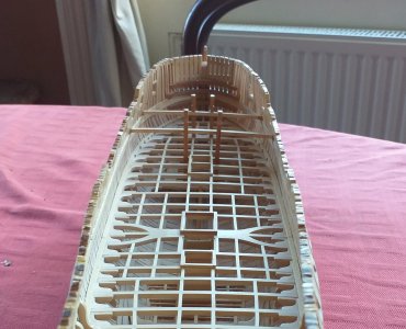
Margin planks, riding bitts?, and the first of the hatch combings fitted. I plan to make gratings (following the method illustrated by Mustafa's brilliant USS Constitution build log). If successful I'll use it for some of the other hatches on the lower deck to create a bit of contrast and variety. The supplied gratings in my kit are very burnt and not really to my liking. 20251009_124045.jpg
 
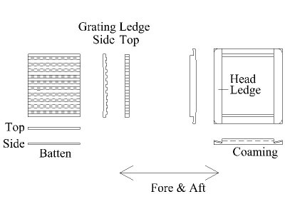
Probably not super important, just an FYI for the future, the head ledges sit on top of the coamings. Hard to tell from the photos, but it looks like your coamings are on top of the head ledges. Also the corners above the level of the deck planks were usually rounded off.

Allan

1760012609796.jpeg
 
Hi Allan,
Yes I'm following the 'instruction' or plans for the model which are not clear. On the upper deck I'll see what I can do, but the pieces are 1.5mm sq and the wood is a little more brittle than I'm used to.
Rounding the corners will be easy, but the correct joinery at 1:96 is beyond me and may not be noticable. I tried beading a knee and that wasn't worth the effort.

The supplied gratings are not usable, and when I tried to fabricate my own it just didn't look right. The model, as I am making it, is focussed on the major structures of the ship and not soo much on the fittings and details. I'm undecided about pretty much every aspect of it until I try things out. Some thing look 'right' to me, and some appear jarring.
 
The supplied gratings are not usable, and when I tried to fabricate my own it just didn't look right.
Makng proper gratings at 1:48 requires specific tools and it is not the easiest thing to do. At 1:96 it can be even more difficult. The main things for the gratings are the openings are no more than about 2.5" to 3" square and the battens run (or appear to run) fore and aft, not athwartships.
Allan
 
Makng proper gratings at 1:48 requires specific tools and it is not the easiest thing to do. At 1:96 it can be even more difficult. The main things for the gratings are the openings are no more than about 2.5" to 3" square and the battens run (or appear to run) fore and aft, not athwartships.
Allan
It wasn't so much the manufacturing process, which was a challenge as it required 0.75 mm openings, it was the aestheics.......

The model is developing as a collection of large scale perpendicular shapes. These are in a sense surrounded by the hanging, lodging and standing knees, which add curvature and 'frame' the structure, along with the gentle curve of the hull. In my opinion, the fine detail of the gratings broke the visual cohesion. I placed the figurehead on yesterday and, again in my opinion, it had the same effect. If I added more fine detail across the entire ship it would be more 'balanced', but I'm going to stick to a minimalist approach. for the moment at least.

I rather enjoy the challenge of balancing historical accuracy, precision, aesthetics and practicality, but it does slow me down as I mull over things for long periods.

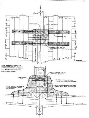
Allan, I also have a question about the mast steps, which are missing in the kit. Would the following drawing be accurate?.....
the second image is the mizzen step as installed by the manufacturer on a prototype.

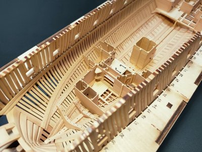
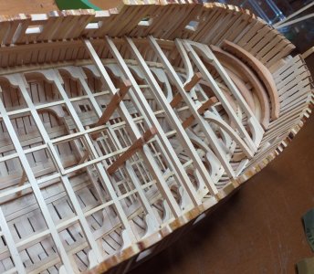
Image 3 is my current progress in the bow region. Drew a sigh of relief when the bitts lined up between the orlop deck, lower deck and upper deck.


1799024655_MastStep.thumb.jpeg.8c10ced555a1fa1260e5df1a2158162e.jpeg


IMG20240325232941.jpg

20251010_081551.jpg
T
 
Last edited:
First, your build is spectacular, congrats!
Mast steps were pretty simple units at the time of Enterprise 1775 but sometimes sat differently depending on the size of the ship and the era.
Sizes are easy.......... From the contract:
MIZEN STEP ….. The Mizen Step to be sided 14 ½ ins, of sufficient Depth on the Keelson, The Arms 5ft 6ins long each, & bolted with 6 bolts of 1 ⅛ dia'r.
MAIN STEP ….. The main Step to be sided 1 ft 11 ins and 15 ins deep on the Keelson and of a length to slide easy by the Stantions of the Well.
FORE STEP ….. The Fore Step to be sided 1 ft 9 ins, in Length 10 ft 6 ins, bolted 6 bolts of 1 ⅛ dia'r

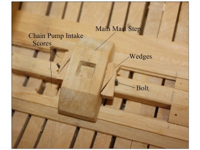
Keep in mind the main mast step is wedged in place so it can be moved fore and aft to adjust the rake of the mast. For the foremast step, it sometimes sat between two crutches, but from the original plans it appears this was not the case. I did just now notice that the foremast location was changed from the original location but I only have the low resolution plan so cannot make out the notes about this.

The mizzen step was sometimes also part of a crutch, but does not appear to be the case for Enterprise. based on the contract which indicates one crutch and is separate from the step.
CRUTCHES In HOLD To have 1 Crutch in the Run Abaft the Mizen Step, sided 9 ins The Arms 5ft 6 ins long, & bolted with 7 bolts 1 dia'r.


Main mast step with wedges
1760090232806.jpeg

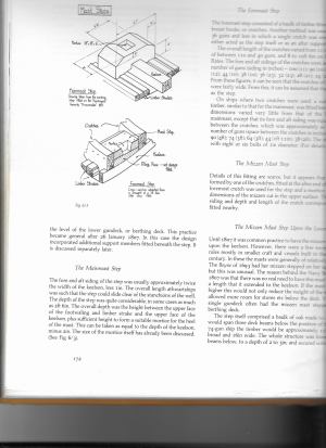
General shapes of foremast step and main mast step. As the foremast step on Enterprise is not bordered by crutches, I would go with the same basic shape as the main step. Shaping it to fit the is more of a challenge than the main mast step, but it helps to start by making a cardboard template based on the body plan drawing. It will get you close but then it gets to be fun getting the exact shape. Ignore the dimensions in the drawing below as it is from Trincomalee, but the shape is typical. The following is from Peter Goodwin's, The Construction and Fitting of the English Man of War.

1760091065311.png
'
 
Thank you Allen for your appreciation and that comprehensive explanation of the 'way of the mast step'. I'll be working on it soon because I should have done so before completing the lower deck and it already requires a fair bit of keyhole surgery.
 
requires a fair bit of keyhole surgery.
I think with the well in place you it would be nigh impossible to have the wedges set up for the main mast. Maybe just the step itself or fake the wedges by gluing them to the fore and aft side of the step before putting the whole thing in place over the keelson.
I am happy that you found the information useful.

Allan
 
Back
Top