- Joined
- Jan 10, 2022
- Messages
- 860
- Points
- 403

Thank you Shota and thanks to everyone for your comments and support. It really is encouragingDear keef
such a beautiful progress, the hull looks great, well done my friend
 |
As a way to introduce our brass coins to the community, we will raffle off a free coin during the month of August. Follow link ABOVE for instructions for entering. |
 |
 |
The beloved Ships in Scale Magazine is back and charting a new course for 2026! Discover new skills, new techniques, and new inspirations in every issue. NOTE THAT OUR FIRST ISSUE WILL BE JAN/FEB 2026 |
 |

Thank you Shota and thanks to everyone for your comments and support. It really is encouragingDear keef
such a beautiful progress, the hull looks great, well done my friend
Keith,Jig parts B17a, b and c have been added to the cradle to support the counter timbers. The outer timbers, port and stbd are made up of 2 parts and sanded to form the fashion pieces, I think they're called. A cross frame, which took a very small amount of adjustment has also been fitted which I hope will give a little more support to what could be a very easily knocked and broken assembly
View attachment 536770
View attachment 536771
View attachment 536772
View attachment 536773
View attachment 536774
View attachment 536775
View attachment 536776
View attachment 536777
View attachment 536778
View attachment 536779
View attachment 536780
View attachment 536781
View attachment 536782
View attachment 536783
FWIW, I simply ripped some strips from the extra material left from the futtock sheets in various thickness’.have you found out more about these spacers please

AMAZING WORK AGAIN thanksKeith,
Very nice and neat.
One little addition I added you might consider.
All the work around the counter timbers makes me nervous so I drew down some bamboo skewers and drilled through the bottoms of the timbers into top transom and glued with medium CA and sanded.
The pins added a surprising amount of extra strength.
Tim

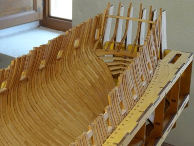
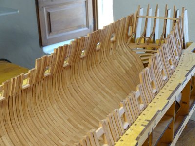
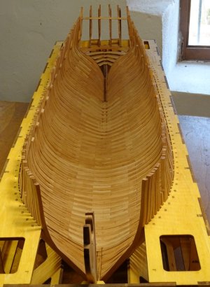
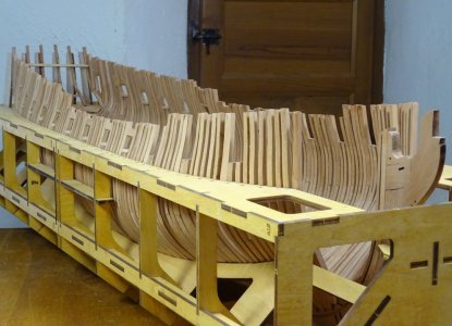
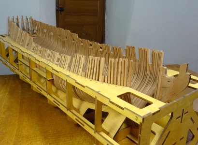
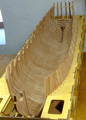
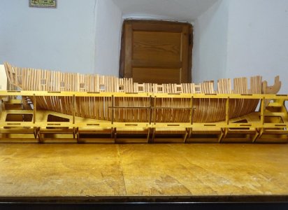
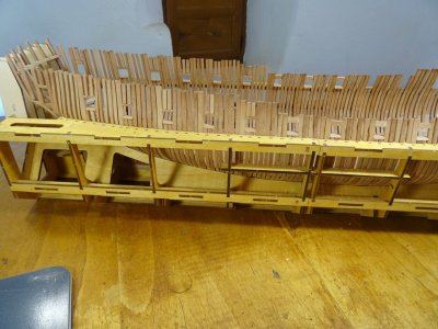
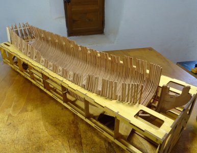
Very nice. Curious, where did you acquire a dimension to get accurate sill bottoms?Starting on the gun ports sills now. I got their positions by finding the height of the top of the jig in relation to the bottom of the keel, which I worked out to be 13.3 centimeters and drew the line on the 1:1 drawing. All the ribs that support the lower sills have to be trimmed down by between 2 to 4 mm approx and it looks like every rib will need the same taken out of their height for the top rails
View attachment 539264
View attachment 539265
View attachment 539266
View attachment 539267
View attachment 539268
View attachment 539269
View attachment 539270
View attachment 539271
View attachment 539272
I am curious as well. If nothing else, they can be found on the framing disposition drawing ZAZ3312 held at RMG in high resolution on the Wiki Commons site. It may a little off as this is a drawing for Hind (28) 1785. The dimensions are also in the contract for Enterprise's sister ship Aurora dated July 16, 1776. There is a partial framing plan HIL0079 on the RMG Collections site for Medea 1778. They all have the sills with about the same depth.Curious, where did you acquire a dimension to get accurate sill bottoms?

For this kit, to match with the 1:1 drawing supplied all that's needed is to take the depth of the jig (15.3 cm) minus the 2 cm that the keel is raised inside the jig (13.3 cm). Draw this line on the plan and measure each sill, top and bottom from this line. If it is anything more complicated than that, then I have done it wrong. But it appears everything fits fine so far. Time will tell thoughVery nice. Curious, where did you acquire a dimension to get accurate sill bottoms?
I am past that but still curious.
I did find several paired frame ends had a slight mismatch and I brought high end down but not in all cases. I think I’m good…. Pulled planks from the sheets….the ones that are initial run and match up with ports and while they look like they’d require a bit of fiddling they seem to run properly……we’ll just have to see.
Currently and slowly, trying to fit deck clamps with the jig fixtures. Slow process to get accurate.
Tim

Thank you very much Jeff, Gunther and DanielReally fine work Keef.
Keith,For this kit, to match with the 1:1 drawing supplied all that's needed is to take the depth of the jig (15.3 cm) minus the 2 cm that the keel is raised inside the jig (13.3 cm). Draw this line on the plan and measure each sill, top and bottom from this line. If it is anything more complicated than that, then I have done it wrong. But it appears everything fits fine so far. Time will tell though
Good morning Keith. Yep looks like you are owning this Enterprise. Nice. Cheers GrantStarting on the gun ports sills now. I got their positions by finding the height of the top of the jig in relation to the bottom of the keel, which I worked out to be 13.3 centimeters and drew the line on the 1:1 drawing. All the ribs that support the lower sills have to be trimmed down by between 2 to 4 mm approx and it looks like every rib will need the same taken out of their height for the top rails
View attachment 539264
View attachment 539265
View attachment 539266
View attachment 539267
View attachment 539268
View attachment 539269
View attachment 539270
View attachment 539271
View attachment 539272


Thanks very much GrantGood morning Keith. Yep looks like you are owning this Enterprise. Nice. Cheers Grant


Thanks Richard. How are you finding it so far?Its all looking really Good
Nice Work
Ian fitting the X FRames slowly buy surely #

Love itThanks Richard. How are you finding it so far?

Same as me. Need replacement part for rib 6. Been waiting 5 weeks nowLove it
Not as clean as your but i am happy
WAiting for a part from Victor WEll actually he will not answer
I need a new Hawse Piece and i dony have any PEAR wood
I decided to look at the Fore Platform JUst as somthing else to do
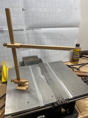
Love it. I really like that it is made from simple assembled pieces showing that making an accurate height gage can be done with hand tools.I made , for a previous build, an adjustable height gauge
