Not that I know of Richard. I am sending a note to a friend/expert that may be able to help on this. If he does have an answer I will post it.has anybody answered this please
Allan
 |
As a way to introduce our brass coins to the community, we will raffle off a free coin during the month of August. Follow link ABOVE for instructions for entering. |
 |
 |
The beloved Ships in Scale Magazine is back and charting a new course for 2026! Discover new skills, new techniques, and new inspirations in every issue. NOTE THAT OUR FIRST ISSUE WILL BE JAN/FEB 2026 |
 |
Not that I know of Richard. I am sending a note to a friend/expert that may be able to help on this. If he does have an answer I will post it.has anybody answered this please
Yes, if I understand correctly I have as well as pictures shown in Arban's build , post #20.has anybody answered this please

The spacers are for the Top of The FramesYes, if I understand correctly I have as well as pictures shown in Arban's build , post #20.
If you look at his photo you will see he has installed spacers, same width as jig spacers about 25% down from the top......this is period correct.
In reality the bollards were cut to be tight together and then tops/bottoms were relieved slightly to create air spaces. Not possible with this kit so accomplished with shim stock.
Like I said, look at his post #20, between the bollards which are not the same.The spacers are for the Top of The Frames

Sorry I am asking about spacers on the Top of the framesLike I said, look at his post #20, between the bollards which are not the same.
![IMG_20250726_193509[1].jpg IMG_20250726_193509[1].jpg](https://shipsofscale.com/sosforums/data/attachments/517/517945-2da2ec42e52b88d52f4acde0dd7b9ca9.jpg?hash=Jn7HCf2h21)
For the tops, no hard fast rule, especially since everything will be planked over.Sorry I am asking about spacers on the Top of the frames
Victor says "The fillers should be 1mm and 2mm strips from the laser cut sheets. You can cut them to appropriate length and place them between the frames. They are not like the fully filled type that we had on Blandford"
Just wondering What the appropriate length is ie how far they go as we have no other references
View attachment 534166
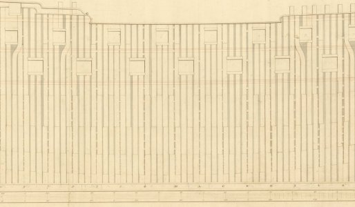
This framing is more like on Admiralty models than the actual ships so go with whatever works best. Even on the actual ships there were spacers at times, and the size of the spacers varied all over the place even on the same ship as the frames were set up to form the gun ports. Below example is Vengeance 1774. You can see the pieces between frames varies a lot as the siding of the frames varies from the floors to the top timbers. These spacers are only on the station lines but I have no idea why.no hard fast rule
You are always the amazing source of documentation !As
This framing is more like on Admiralty models than the actual ships so go with whatever works best. Even on the actual ships there were spacers at times, and the size of the spacers varied all over the place even on the same ship as the frames were set up to form the gun ports. Below example is Vengeance 1774. You can see the pieces between frames varies a lot as the siding of the frames varies from the floors to the top timbers. These spacers are only on the station lines but I have no idea why.
Allan
View attachment 534232

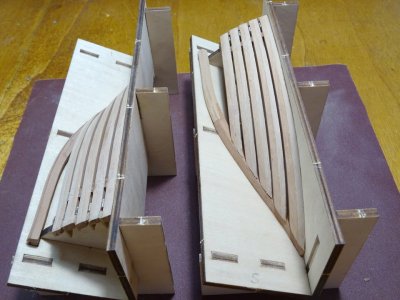
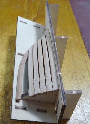
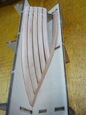
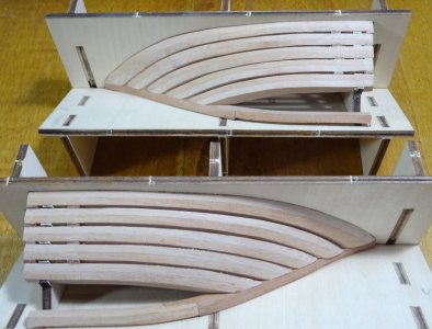
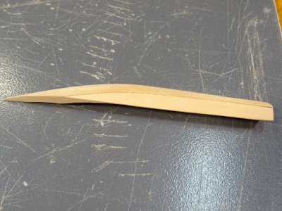
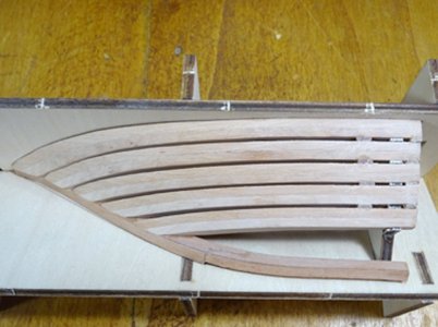
Wonderful Keith. You are owning this . Cheers GrantThe hawse port and starboard are nearly complete, with 1mm spacers placed between the frames. Not having any reference, I'm not sure if this is correct, but they give some much needed support so have gone ahead with it. They will be planked over so will not be visible anyway. The shaping of the frames are pretty obvious, until you get to the last 2, frames 6 and 7, where they do take some thought and working out. Unfortunately, I have made an error with the shaping of the stbd. frame 6 and 7 and they are damaged beyond repair. I have notified Victor at Modelship Dockyard for replacement parts and although being extremely busy, has replied and offered to send the parts free of charge. This after sales service is excellent. Thank you Victor Zhing
View attachment 534262
View attachment 534263
View attachment 534264
View attachment 534265
View attachment 534266
View attachment 534267
Nice work, Keith. And a great service from Victor.The hawse port and starboard are nearly complete, with 1mm spacers placed between the frames. Not having any reference, I'm not sure if this is correct, but they give some much needed support so have gone ahead with it. They will be planked over so will not be visible anyway. The shaping of the frames are pretty obvious, until you get to the last 2, frames 6 and 7, where they do take some thought and working out. Unfortunately, I have made an error with the shaping of the stbd. frame 6 and 7 and they are damaged beyond repair. I have notified Victor at Modelship Dockyard for replacement parts and although being extremely busy, has replied and offered to send the parts free of charge. This after sales service is excellent. Thank you Victor Zhing
View attachment 534262
View attachment 534263
View attachment 534264
View attachment 534265
View attachment 534266
View attachment 534267

Thank you very much. The 7 frames that make up the hawse, port and stbd are each made up of two halves glued together, with sanding lines etched on both sides which form the curve for the inner and outer face of each frame. The first 5 frames are obvious as to which side to sand to, but frames 6 and 7, because of the direction the curve of the bow are much less obvious and I sanded 2 of these frames in the wrong direction. This is quite a complicated part of the build and it only takes one slip up to ruin the frameHello Keith,
I only discovered this build this morning. Amazing workmanship! You noted that you made a mistake on stbd. frame 6 and 7. Could you please be more specific? I am learning much from your build and from @AllanKP69 who seems to be a wealth of knowledge on how ships were actually built.
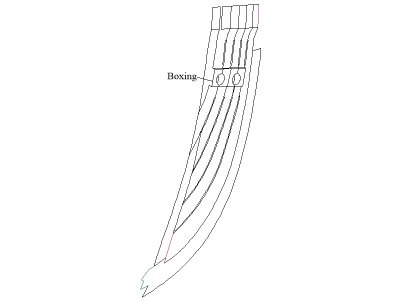
For my part, it is not that much wealth, but rather a combination of the love of research and friends that know WAY more than I do and are always happy to answer my questions, the boxing being an example.I am learning much from your build and from @AllanKP69 who seems to be a wealth of knowledge on how ships were actually built.
I suspect these additional spacers were added to give a little more rigidity going up between the gun ports.As
This framing is more like on Admiralty models than the actual ships so go with whatever works best. Even on the actual ships there were spacers at times, and the size of the spacers varied all over the place even on the same ship as the frames were set up to form the gun ports. Below example is Vengeance 1774. You can see the pieces between frames varies a lot as the siding of the frames varies from the floors to the top timbers. These spacers are only on the station lines but I have no idea why.
Allan
View attachment 534232

The Chinese kits supply downloadable 'manuals' with only 3D drawings as instructions. I can understand why this is the preferred method, as to provide written instructions translated into every main language would greatly add to the expense and development time of producing their kits.Hello Keith,
Thanks for the explanation. Would you mind posting a photo of the error? I'm trying to learn from your experience as well as others.
Though I've done some modeling, my experience level is not as great as yours thus the request to learn more about it.
I've found the directions in many of the kit models to be sorely lacking as they make many assumptions that the builders of their models are experienced experts.
Many tips and to do's vs. not's are omitted along with clear and concise instructions during the framing build.
