-

Win a Free Custom Engraved Brass Coin!!!
As a way to introduce our brass coins to the community, we will raffle off a free coin during the month of August. Follow link ABOVE for instructions for entering.
-

PRE-ORDER SHIPS IN SCALE TODAY!
The beloved Ships in Scale Magazine is back and charting a new course for 2026!
Discover new skills, new techniques, and new inspirations in every issue.
NOTE THAT OUR FIRST ISSUE WILL BE JAN/FEB 2026
- Home
- Forums
- Ships of Scale Group Builds and Projects
- Modelship Dockyard PoF HMS Enterprize 1774 - 1/48
You are using an out of date browser. It may not display this or other websites correctly.
You should upgrade or use an alternative browser.
You should upgrade or use an alternative browser.
- Joined
- Jul 17, 2024
- Messages
- 75
- Points
- 113

Hello Keeth,
I am glad to read that you have recovered and found your way back to the shipyard.
For several months now I have been following your build log, and I must say that you can be proud of your work. I myself am considering putting the Enterprise on my wish list after completing my Victory. It seems to me quite a challenge to switch from a POB to a POF model.
You now have the hull with the keel and all its frames finished, and you are working on the gun ports. To what extent do you want to make the hull an open construction, so that one can also look inside the ship? I myself would like to build an open model, in which all decks are visible and can be fitted out.
What is your view on this?
- Joined
- Jan 10, 2022
- Messages
- 860
- Points
- 403

Thank you for your kind thoughts. I have given some thought to the finished construction and have decided to plank the hull only down to the wales, port and straboard, leaving all the lower frames and keel exposed. All the deck timbers will be left exposed, except maybe half planking of the lower decks to facilitate the mounting of the cabin walls and bulkheads. I am glad you have plans to build this excellent kit. It is not difficult at all to change from POB to POF, just more woodwork involved but less rigging . I wish you well with your present Victory project. It is a great subjectHello Keeth,
I am glad to read that you have recovered and found your way back to the shipyard.
For several months now I have been following your build log, and I must say that you can be proud of your work. I myself am considering putting the Enterprise on my wish list after completing my Victory. It seems to me quite a challenge to switch from a POB to a POF model.
You now have the hull with the keel and all its frames finished, and you are working on the gun ports. To what extent do you want to make the hull an open construction, so that one can also look inside the ship? I myself would like to build an open model, in which all decks are visible and can be fitted out.
What is your view on this?
- Joined
- Jan 10, 2022
- Messages
- 860
- Points
- 403

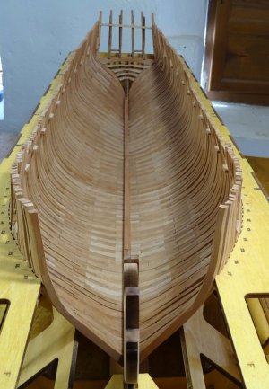
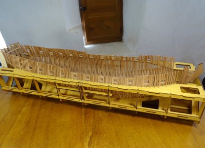
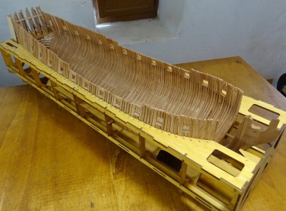
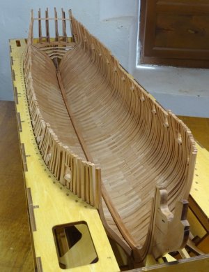
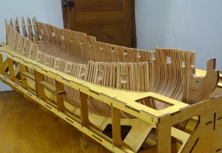
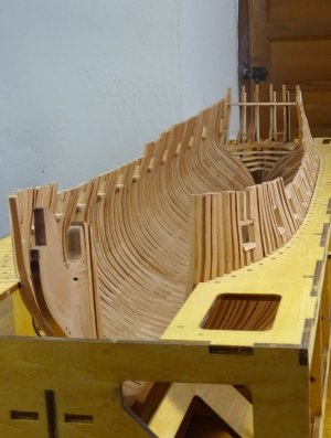
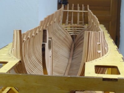
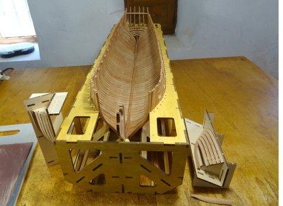
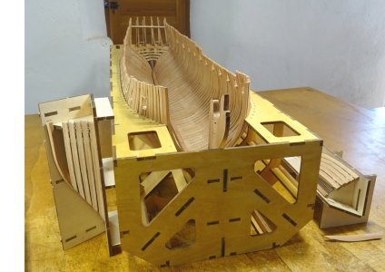
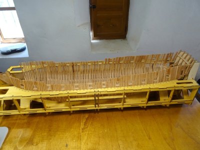
It has been a while since I last posted. That's because there is not really much to see. I have added the keelson, which fitted perfectly and also trimmed the frames to their correct heights, a time consuming task with little visual effect but I think it has cleaned up the shape of the hull rather well. I got the heights by measuring the depth of the jig in relation to the bottom of the keel and transferring this position onto the 1:1 drawing. Then it was a matter of taking the height of each frame. The amount of trimming needed varied from around 4 to 6 mm at the bow and stern to only up to 2 mm above the mid ship gun ports


Last edited:
- Joined
- Apr 20, 2020
- Messages
- 6,242
- Points
- 738

that going to be a beautiful hull of the ship, well done KeefIt has been a while since I last posted. That's because there is not really much to see. I have added the keelson, which fitted perfectly and also trimmed the frames to their correct heights, a time consuming task with little visual effect but I think it has cleaned up the shape of the hull rather well
View attachment 550207
View attachment 550208
View attachment 550209
View attachment 550210
View attachment 550211
View attachment 550212
View attachment 550213
View attachment 550214
View attachment 550215
View attachment 550216
That’s looking very nice, Keith. Although it looks a small step, for sure it’s time consuming.It has been a while since I last posted. That's because there is not really much to see. I have added the keelson, which fitted perfectly and also trimmed the frames to their correct heights, a time consuming task with little visual effect but I think it has cleaned up the shape of the hull rather well. I got the heights by measuring the depth of the jig in relation to the bottom of the keel and transferring this position onto the 1:1 drawing. Then it was a matter of taking the height of each frame. The amount of trimming needed varied from around 4 to 6 mm at the bow and stern to only up to 2 mm above the mid ship gun ports
View attachment 550207
View attachment 550208
View attachment 550209
View attachment 550210
View attachment 550211
View attachment 550212
View attachment 550213
View attachment 550214
View attachment 550215
View attachment 550216
Regards, Peter
- Joined
- Jan 10, 2022
- Messages
- 860
- Points
- 403

Thank you. I very much appreciate your interest and commentthat going to be a beautiful hull of the ship, well done Keef
- Joined
- Jan 10, 2022
- Messages
- 860
- Points
- 403

It surely was, but I'm pleased with the result. Needs some small adjustments in placesThat’s looking very nice, Keith. Although it looks a small step, for sure it’s time consuming.
Regards, Peter
Everything is looking really good. The fairing is extremely smooth.
Hard to tell how much taper on the knee of the head that you did from the photos but thought the following from the contract might be of interest.
Allan
The knee of the head to extend to the upper side of the upper cheek, to be 11¾ ins thick at the stem and 6 ins at the fore end
Hard to tell how much taper on the knee of the head that you did from the photos but thought the following from the contract might be of interest.
Allan
The knee of the head to extend to the upper side of the upper cheek, to be 11¾ ins thick at the stem and 6 ins at the fore end
Good morning Keith. You definitely know what you are doing. As always beautiful work. Cheers GrantIt has been a while since I last posted. That's because there is not really much to see. I have added the keelson, which fitted perfectly and also trimmed the frames to their correct heights, a time consuming task with little visual effect but I think it has cleaned up the shape of the hull rather well. I got the heights by measuring the depth of the jig in relation to the bottom of the keel and transferring this position onto the 1:1 drawing. Then it was a matter of taking the height of each frame. The amount of trimming needed varied from around 4 to 6 mm at the bow and stern to only up to 2 mm above the mid ship gun ports
View attachment 550207
View attachment 550208
View attachment 550209
View attachment 550210
View attachment 550211
View attachment 550212
View attachment 550213
View attachment 550214
View attachment 550215
View attachment 550216
She is looking great !!It has been a while since I last posted. That's because there is not really much to see. I have added the keelson, which fitted perfectly and also trimmed the frames to their correct heights, a time consuming task with little visual effect but I think it has cleaned up the shape of the hull rather well. I got the heights by measuring the depth of the jig in relation to the bottom of the keel and transferring this position onto the 1:1 drawing. Then it was a matter of taking the height of each frame. The amount of trimming needed varied from around 4 to 6 mm at the bow and stern to only up to 2 mm above the mid ship gun ports
View attachment 550207
View attachment 550208
View attachment 550209
View attachment 550210
View attachment 550211
View attachment 550212
View attachment 550213
View attachment 550214
View attachment 550215
View attachment 550216
- Joined
- Jan 10, 2022
- Messages
- 860
- Points
- 403

THANKS JeffShe is looking great !!

- Joined
- Jul 24, 2016
- Messages
- 540
- Points
- 188

Where do we get the height of the Cross Member on the stern pleaseJig parts B17a, b and c have been added to the cradle to support the counter timbers. The outer timbers, port and stbd are made up of 2 parts and sanded to form the fashion pieces, I think they're called. A cross frame, which took a very small amount of adjustment has also been fitted which I hope will give a little more support to what could be a very easily knocked and broken assembly
View attachment 536770
View attachment 536771
View attachment 536772
View attachment 536773
View attachment 536774
View attachment 536775
View attachment 536776
View attachment 536777
View attachment 536778
View attachment 536779
View attachment 536780
View attachment 536781
View attachment 536782
View attachment 536783
- Joined
- Jul 24, 2016
- Messages
- 540
- Points
- 188

if you thought the Caldercraft Victory was Good And it isKeef, you’re creating a beautiful piece of work. What craftsmanship you’re showing here. I certainly won’t forget your build log when I start on this kit myself sometime in the future. The same goes for the comments from the other builders who are adding to your report — it’s a wonderful complement to the construction manual. You can be proud of this.
For now, I’ll first focus on finishing my Victory.
This ENterprize is amazing
But really needs a lot of looking at as the instructions are not good
- Joined
- Jul 24, 2016
- Messages
- 540
- Points
- 188

i find a little touch of glue at top and bottom of the two smaller frames help align itShaping the frames of the hawse pieces. Only dry fit at the moment
View attachment 533732
View attachment 533733
View attachment 533734
OK, a question for you.Thank you. I very much appreciate your interest and comment
I'm guessing from your pics you used the supplied cross piece for the transom ? One area I am conflicted about as the kit is not entirely historically accurate although I've done nothing but dry fit.
My question is thus...if you look at historical images, right below transom windows there is molding that stands proud of the flat sheet with windows that extends to edges and continues under doors until it ties into hull.....i.e.3 pieces.
I have actually made a curved piece that would be tight to bottom of transom and represent that moulding once I scrape the edges with a molding scraper.
Plan B, I suppose might be to consider molding after the fact, guessing this was how it was done much the same as above the Wales.
I think this will work....dry fit presents well, but still scratching my head.
Appreciate any thoughts.......trying to plan a few steps ahead.
Tim
Are you talking about part G7-3B? It is shown in step 114 for the stern.OK, a question for you.
I'm guessing from your pics you used the supplied cross piece for the transom ? One area I am conflicted about as the kit is not entirely historically accurate although I've done nothing but dry fit.
My question is thus...if you look at historical images, right below transom windows there is molding that stands proud of the flat sheet with windows that extends to edges and continues under doors until it ties into hull.....i.e.3 pieces.
I have actually made a curved piece that would be tight to bottom of transom and represent that moulding once I scrape the edges with a molding scraper.
Plan B, I suppose might be to consider molding after the fact, guessing this was how it was done much the same as above the Wales.
I think this will work....dry fit presents well, but still scratching my head.
Appreciate any thoughts.......trying to plan a few steps ahead.
Tim
- Joined
- Jan 10, 2022
- Messages
- 860
- Points
- 403

Hi Tim. I have not been able to get into my workshop, or concentrate on the build for a few weeks and maybe for some yet, due to health issues. Really looking forward to getting back and continuing as normal ASAPOK, a question for you.
I'm guessing from your pics you used the supplied cross piece for the transom ? One area I am conflicted about as the kit is not entirely historically accurate although I've done nothing but dry fit.
My question is thus...if you look at historical images, right below transom windows there is molding that stands proud of the flat sheet with windows that extends to edges and continues under doors until it ties into hull.....i.e.3 pieces.
I have actually made a curved piece that would be tight to bottom of transom and represent that moulding once I scrape the edges with a molding scraper.
Plan B, I suppose might be to consider molding after the fact, guessing this was how it was done much the same as above the Wales.
I think this will work....dry fit presents well, but still scratching my head.
Appreciate any thoughts.......trying to plan a few steps ahead.
Tim
Very sorry to hear that Keith ! I hope what ever it is passes quickly and you can get back to that wonderful ship you're building !Hi Tim. I have not been able to get into my workshop, or concentrate on the build for a few weeks and maybe for some yet, due to health issues. Really looking forward to getting back and continuing as normal ASAP


 It's great to see you working on your beautiful Enterprise again! I look forward to seeing more progress and pictures from you.

