- Joined
- Dec 31, 2017
- Messages
- 292
- Points
- 158

How are the instructions? Are they in English and are they clear?
 |
As a way to introduce our brass coins to the community, we will raffle off a free coin during the month of August. Follow link ABOVE for instructions for entering. |
 |
 |
The beloved Ships in Scale Magazine is back and charting a new course for 2026! Discover new skills, new techniques, and new inspirations in every issue. NOTE THAT OUR FIRST ISSUE WILL BE JAN/FEB 2026 |
 |

The information in the construction instructions is very brief. The instructions can be downloaded from the homepage https://drydockmodelsandparts.com/c...-pearwood-boxwood-cnc-decorations-coming-soon. In conjunction with the YouTube videos it becomes easy to understand, without the videos it would be very difficultHow are the instructions? Are they in English and are they clear?
Hallo Mario alias @empeHello everyone,
On Tuesday I received the beautiful kit of the HMS Enterprize 1774 1:96 from Dry-Dock Models & Parts.
It has very cleanly lasered parts and very detailed CNC milled parts made of boxwood such as the figurehead and the transom, which are also included as a 3D printed version.
There are also 3D prints of the cooking area, the steering wheel, tiny columns, lanterns and much more. There is also a large etching board with some very tiny parts. 2 plans in original size, one with 3 side views and one with the deck details in plan view, there are also countless plans for the construction of the frames. You can download the construction plan from Dry-Dock Models.
The slipway and some templates are laser cut from plywood.
Now there is a small selection of pictures
Greetings Mario
View attachment 420802
View attachment 420803
View attachment 420804
View attachment 420805
View attachment 420806
View attachment 420807
View attachment 420808
View attachment 420809
View attachment 420810
View attachment 420811

I enjoy sanding too. The beautiful lines of the hull become apparent after the hours spent sanding inside and out.I love to sanding
I hope, i can Show a little more at Augsburg
Thank youSchleifen macht mir auch Spaß. Die schönen Linien des Rumpfes werden nach stundenlangem Schleifen innen und außen deutlich.
Sie kommt gut zurecht. Viel Spaß beim Bauen.
Grüße
Rick
Good morning. One frame at a time....."slowly slowly you will catch this monkey". All looking awesome . Cheers grantHello everyone,
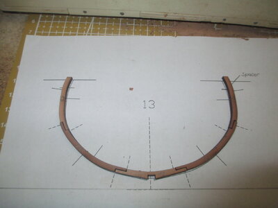
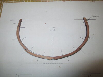
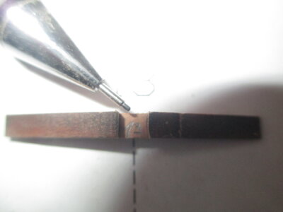
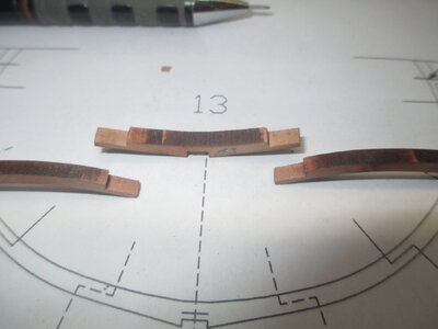
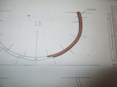
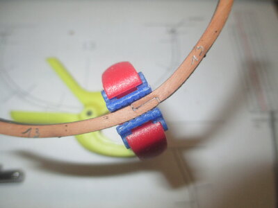
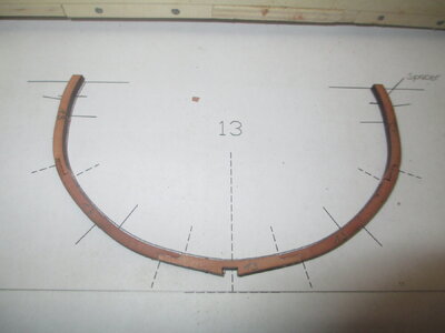
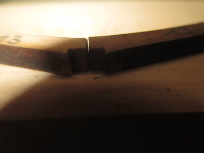
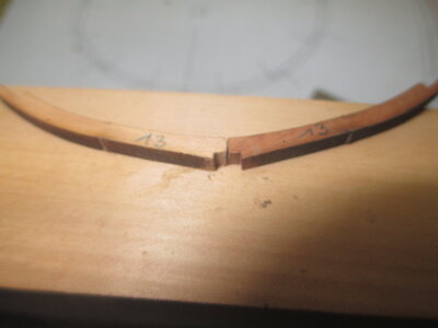
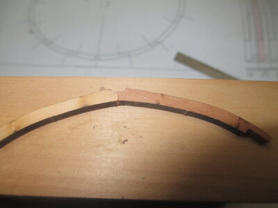
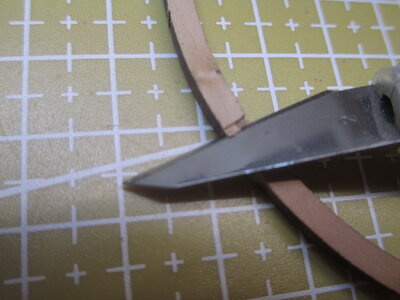
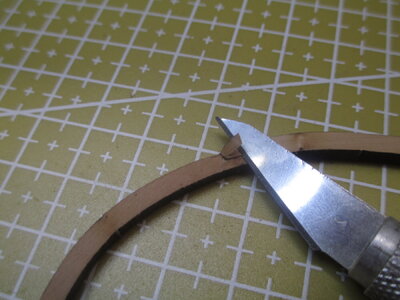
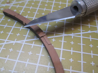
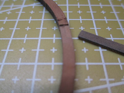
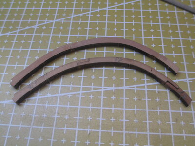
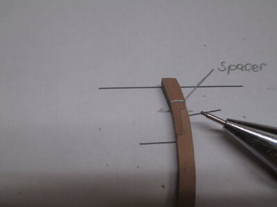
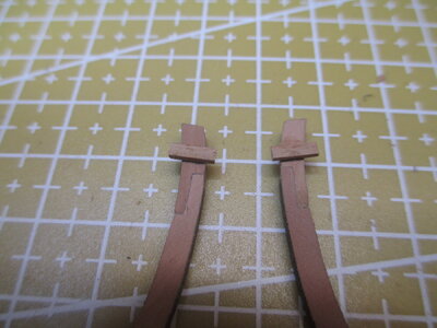
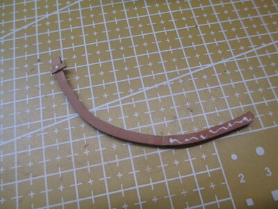
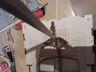
It's probably time for a little update, I'm making slow progress due to work. The "curved" frames are particularly interesting; they require good concentration.
Here are some cell phone pictures.
Kind regards Mario
View attachment 445005
View attachment 445006
View attachment 445007
View attachment 445008
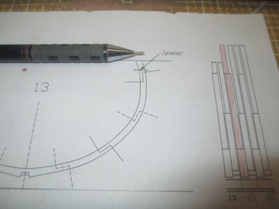
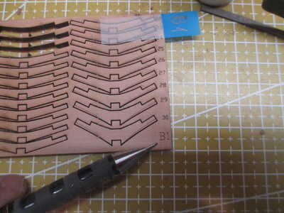
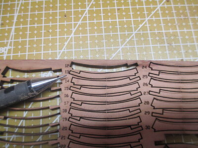
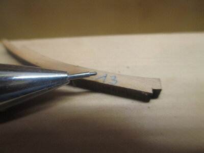
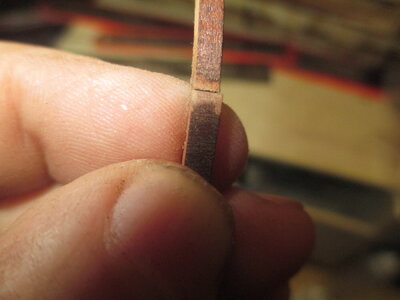
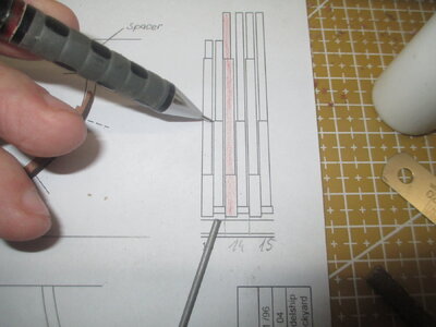
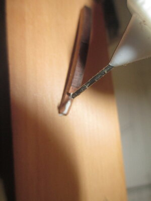
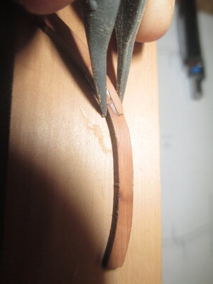
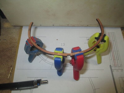
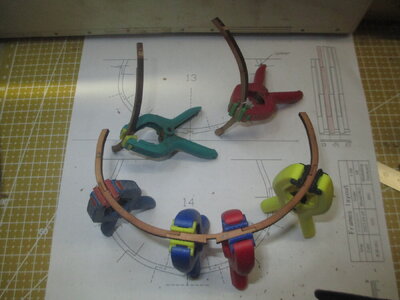
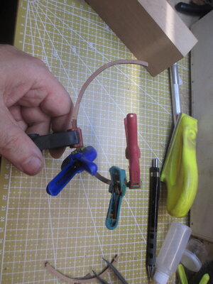
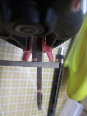
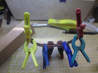
There is a great ship modelling club in Denver, Colorado that meets monthly that is quite active. I would strongly suggest you look them up if you don't mind the drive. There are also some pretty large regional/national events here in the US as well.Great step by step guidance. It is always handy to have lots of small clamps around when building POF kits.
I wish that someone in USA might set up such a meet as you have in Europe for meeting and seeing work done by those you only chat online with.
In my other hobby of Model Railroads, we have regional and national meetings and shows to see what is new and visit with old friends.
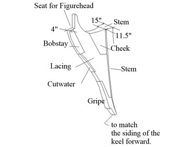

You're right. I did it on my own hoy as some tapering was strictly required by the jig pattern itself. Nevertheless, hardly any planset available in the market shows or explane that. I saw some museum models and the Leda class frigates by Seppings shoving even rounded cutwater's edges possibly in some streamlining attempt.Is there a reason you did not taper the stem or knee of the head? For a 28 gun ship, vertically the stem should go from 15 inches wide and reduce so it matches the width of the keel at the bow. The knee of the head should reduce from 11.5" at the stem down to 4 inches at the foremost edge. I suspect many are unaware of this basic design feature and some may consider this a minor thing. In the end, as normal, its inclusion is up to the builder and the amount of accuracy they want to reach. It is a shame such a basic item is ignored or glossed over by all but one kit manufacturer.
View attachment 447385
It is my understanding that models from kit maker Vanguard mention this as an option for model builder in the instructions. Sadly, Syren is the only kit manufacturer of which I am aware that addresses important design characteristic in some detail.Nevertheless, hardly any planset available in the market shows or explane that.
Not that bad as leaving out all the hanging and lodging knees along with the notches for deck framing ,some manufacturer does that ,in this case is Syren .Those are major flaws in a otherwise very nice Pof kit, all the Chinese Pof kits I seen so far have these fratures ,tapering the bow is up to the builder not a feature or parts that should be include in a very expensive kit!Is there a reason you did not taper the stem or knee of the head? For a 28 gun ship, vertically the stem should go from 15 inches wide and reduce so it matches the width of the keel at the bow. The knee of the head should reduce from 11.5" at the stem down to 4 inches at the foremost edge. I suspect many are unaware of this basic design feature and some may consider this a minor thing. In the end, as normal, its inclusion is up to the builder and the amount of accuracy they want to reach. It is a shame such a basic item is ignored or glossed over by all but one kit manufacturer.
View attachment 447385
