-

Win a Free Custom Engraved Brass Coin!!!
As a way to introduce our brass coins to the community, we will raffle off a free coin during the month of August. Follow link ABOVE for instructions for entering.
-

PRE-ORDER SHIPS IN SCALE TODAY!
The beloved Ships in Scale Magazine is back and charting a new course for 2026!
Discover new skills, new techniques, and new inspirations in every issue.
NOTE THAT OUR FIRST ISSUE WILL BE JAN/FEB 2026
You are using an out of date browser. It may not display this or other websites correctly.
You should upgrade or use an alternative browser.
You should upgrade or use an alternative browser.
HMS GRANADO - full hull - POF kit by CAF in 1:48 - by Uwe
- Joined
- Oct 23, 2018
- Messages
- 886
- Points
- 403

Hello Uwe,
Be careful with your pictures in post 16. You're mixing English and French frameing. The last pictures are showing the French framing for the end of the 18th century. For the limer strakes you should use Goodwin. I did not find any information for limberhols for an English ship of this period (mid 18th century).
I would not show the holes.
Hallo Christian,Hello Uwe,
Be careful with your pictures in post 16. You're mixing English and French frameing. The last pictures are showing the French framing for the end of the 18th century. For the limer strakes you should use Goodwin. I did not find any information for limberhols for an English shipof this period (mid 18th century).
I would not sho the holes.
many thanks for your comment
but I am not mixing french and english! I wrote in the text what is english and what is french.
The last two photos in #16 are taken from the Antomy book of Goodwin showing the Granado pumps.
The third and fourth last photos are from the french 74-gun ship book Vol.1
- Joined
- Oct 23, 2018
- Messages
- 886
- Points
- 403

Hi Uwe,
for this details it is in my opinion not possible to use French shipbuilding details as a reference for en English ship. At minimum at the end of the 18th century the English used "filling frames" between the single and double frames for smaller vessels (David Antscherl describes this for the Swan class sloops), so the timber holes doesn't make sence. I don't know if there is a change to the midcentury way.
for this details it is in my opinion not possible to use French shipbuilding details as a reference for en English ship. At minimum at the end of the 18th century the English used "filling frames" between the single and double frames for smaller vessels (David Antscherl describes this for the Swan class sloops), so the timber holes doesn't make sence. I don't know if there is a change to the midcentury way.
- Joined
- Oct 17, 2020
- Messages
- 1,691
- Points
- 488

Hi Uwek,Hallo Christian,
many thanks for your comment
but I am not mixing french and english! I wrote in the text what is english and what is french.
The last two photos in #16 are taken from the Antomy book of Goodwin showing the Granado pumps.
The third and fourth last photos are from the french 74-gun ship book Vol.1
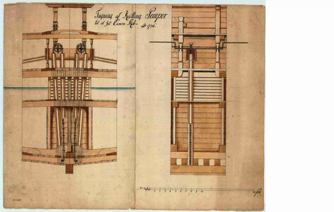
H M S Victory Longridge, page 36, description of the holes "scuppers in the hold". I do not have the book quoted in English
Kurt Konrath
Kurt Konrath
Uwek, at the rate you are building frames the ship will be done in a few weeks. 

Hope I can stay still while standing behind Doc K that long.
Hope I can stay still while standing behind Doc K that long.
I used the french vessel designs to show how these limber holes were looking like. Off course it is necessary to check the first and secondary publications about english ships first.Hi Uwe,
for this details it is in my opinion not possible to use French shipbuilding details as a reference for en English ship. At minimum at the end of the 18th century the English used "filling frames" between the single and double frames for smaller vessels (David Antscherl describes this for the Swan class sloops), so the timber holes doesn't make sence. I don't know if there is a change to the midcentury way.
I also checked the well known books from Peter Goodwin "Construction and Fitting"
Book review - The Construction and Fitting of the Sailing Man-of-War, 1650-1850" by Peter Goodwin
From the early beginning of this review: This book is very recommended and is a invaluable reference for ship modeling. In my opinion a "Must Have" The Construction and Fitting of the Sailing Man-of-War, 1650-1850 (Conway's History of Sail) (Hardcover) by Peter Goodwin (Author) Hardcover: 288...
shipsofscale.com
Here he is describing over pages in chapter the changes of the different framing systems along the time. So wedges to fill between the main and filling frames were used usually later on, so there were some spaces between the frames floor timbers where bilge water stands - and produced some rot
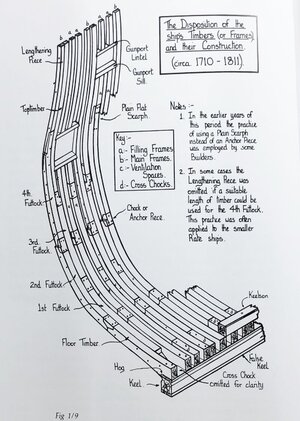
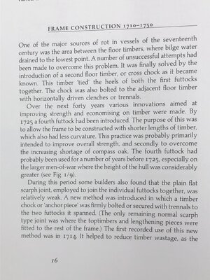
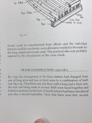
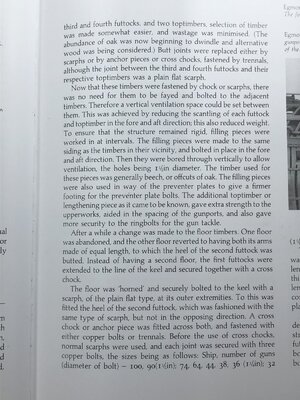
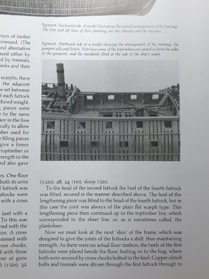
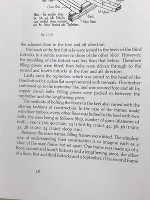
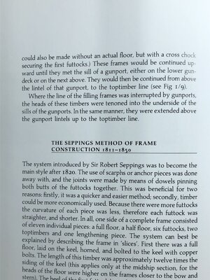
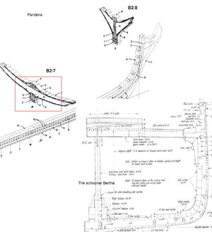
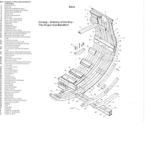
BTW: Goodwin is not showing these holes in his Anatomy books about the Granado and also not in his Blandford ......
Than I checked Brian Lavery "Armin and Fitting ....."
Book review - Book Review / Look Inside: "The Arming and Fitting of English Ships of War, 1600-1815" by Brian Lavery
Arming and Fitting of English Ships of War 1600-1815 by Brian Lavery Hardcover: 319 pages Publisher: Naval Inst Pr; 1st Edition edition (March 1, 1988) Language: English ISBN-10: 0870210092 ISBN-13: 978-0870210099 Product Dimensions: 10.2 x 1 x 12 inches Shipping Weight: 3.9 pounds...
shipsofscale.com
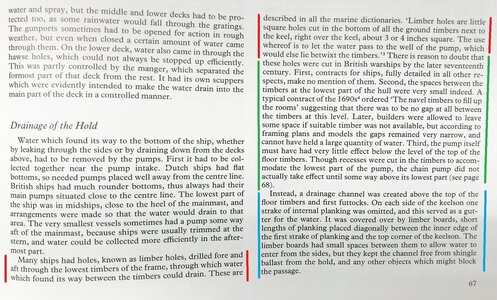
On page 67 he is describing it
Yes, there were limber holes in many ships (red marked area)
I have my doubts, that they were really used by the later 17th century (green marked area)
instead there was a drainage channel left and right to the keelson and the "space" between the frames was filled with wedges (blue marked area)
So ....... ??? .... our ship was launched 1742 .......
nobody knows and I could not find any clear definitive answer in moment ...... so ......
I will make no limber holes, but the limber channel in my model
and will follow Goodwin like showed in his Anatomy book and confirmed somehow by Lavery
Many Thanks btw for all you requests of places and chairs in my workshop - Ok - you convinced me, that I will need some two or three chairs more.
There is no need for you to dig tunnels, using drones or standing around necessary .......
Another short info:
I started the works on the frames a little bit earlier than starting with the log, so I am not soooo fast, working only 1 or 2 hours per day ...... so this build, I assume 500 to 700 hours will take 1,5 to 2 years ....... let us see
This post is not a try to empty my workshop from interested friends, but I thought one additional post with some theory should be necessary and important to show also the difference between the section model and the full hull model
The Framing is completely different !!!!
Here is the framing of the section model - all frame elements were 2D or 3D cnc milled elements
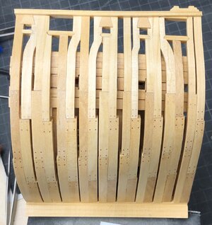
in the photo my own model is shown
Which was following the framing by Goodwin in his anatomy book
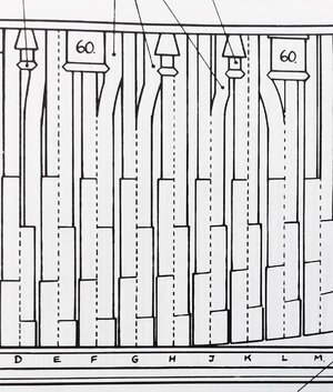
scroll up and down and you will see that
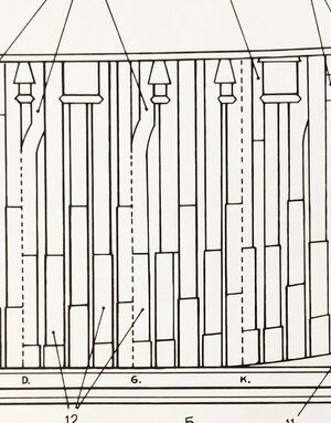
Goodwin was also shown a different alternative for a possible framing structure (double main frames with 2 or three filling frames)
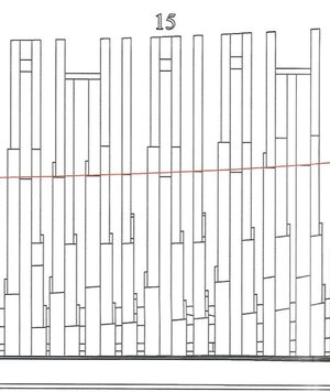
and here you can find the excerpt of the CAF drawing showing the framing of the kit - all elements are laser cut parts
I think it is interesting to know how the framing of the full hull model works
I promise, that with my next post of the building log I will once more show some sawdust and wood
The Framing is completely different !!!!
Here is the framing of the section model - all frame elements were 2D or 3D cnc milled elements

in the photo my own model is shown
Which was following the framing by Goodwin in his anatomy book

scroll up and down and you will see that
Goodwin was also shown a different alternative for a possible framing structure (double main frames with 2 or three filling frames)

and here you can find the excerpt of the CAF drawing showing the framing of the kit - all elements are laser cut parts

I think it is interesting to know how the framing of the full hull model works
I promise, that with my next post of the building log I will once more show some sawdust and wood
Excuse me for breaking in here (you probably didn't see me back here in the shadows, lurking  ). I am trying to understand the principles of POF modeling as commonly used on this forum and others.
When it comes to framing the source material seems to say this:
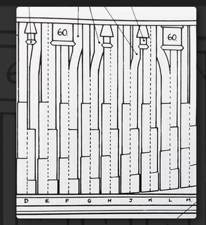
But the kit manufacturer has provided this:
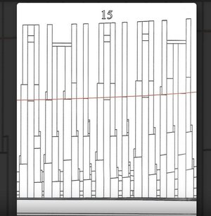
In view of this discrepancy, other than historical or academic interest, isn't the placement of limber holes pretty much up to the whim of the builder?
Fair winds.. Ed
When it comes to framing the source material seems to say this:

But the kit manufacturer has provided this:

In view of this discrepancy, other than historical or academic interest, isn't the placement of limber holes pretty much up to the whim of the builder?
Fair winds.. Ed
Kurt Konrath
Kurt Konrath
We won't hold your feet to the fire on the 1.5 years build time as we don't want you to get burnt out.
I know you also have other things to do, besides keep us all happy and feed while sitting in the shop watching your work.
You say you get 1-2 a day working the kit, and I hope to get 2 hours a week to work on model ships, along with my other hobbies.
I have been doing work in shop to clean up (yes it's spring time in Oklahoma) and get things more easy to work on, and bring in tools from storage to work on projects. Hopefully I will get back to posting on my build logs soon. Oh wait, is that a train whistle I hear calling me to my other hobby.
Keep up the fine work and I am willing to wait 2 years to see her fully completed.
Hi Uwe
I will tag along if I may.The framing on the full hull is obviously that way to keep production costs down.It couldn't really be done with laser and would require a multi axis mill.
If the upper works are fully planked,I would not be concerned.If I were leaving onside unplanked I may be tempted to replace the tops of these frames with scratch built ones.
Kind Regards
Nigel
So it would seem then that in most cases historical accuracy lies solely within the purview of the scratch modeler. That certainly makes a case for their esteem should they choose to follow that path.
Fair winds.. Ed
Fair winds.. Ed
The Granado mid section kit has the correct curved frames like your diagram, but the full hull kit has a slightly simplified arrangement.
Hallo Ed,Excuse me for breaking in here (you probably didn't see me back here in the shadows, lurking). I am trying to understand the principles of POF modeling as commonly used on this forum and others.
When it comes to framing the source material seems to say this:
But the kit manufacturer has provided this:
In view of this discrepancy, other than historical or academic interest, isn't the placement of limber holes pretty much up to the whim of the builder?
Fair winds.. Ed
Many Thanks for your interest in the log, but also in the discussion, and also in your interest in POF-modeling.
Much appreciated
Usually the frame construction of POF-kits are much more simplified, either to make it slightly easier for the modeler, but also to reduce the costs for such kits.
But they follow mainly the way like usually used and executed also in contemporary models, which are available in museum.
These models are showing very simplified framing, usually double frames with the same thickness from the floor timber at the keel up to the top timbers
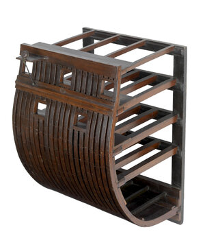
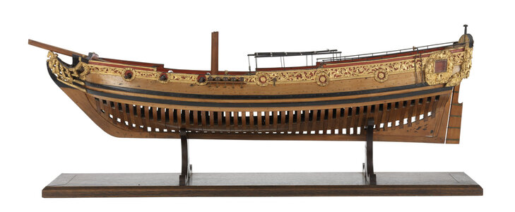
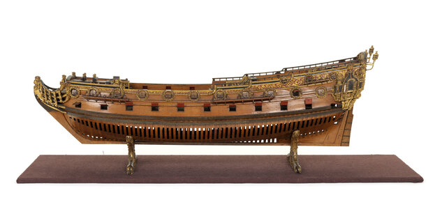
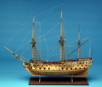
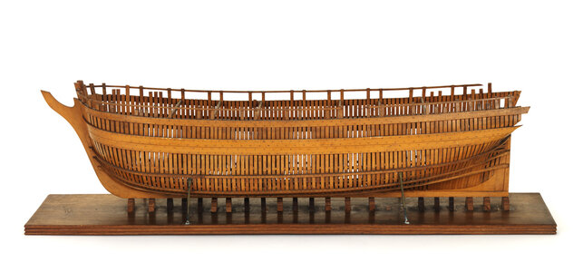
These models, and most of these models in the museum are like this, shall show the hull form, but have no focus on the framing structure
The well known Granado model has double and single frames, but the frames are not reduced in width or other complex framing, just double and single frames of the same width from floor to top
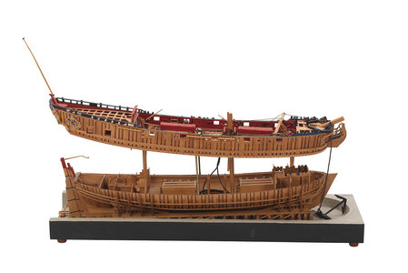
The following are already some models showing partly the reduction of the width in every frame
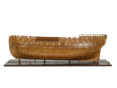
and a very small number also the distortion of the top timbers next or caused by gunports (like here the model of the HMS Intrepit (1770)
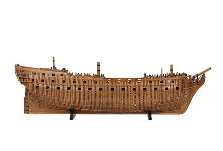
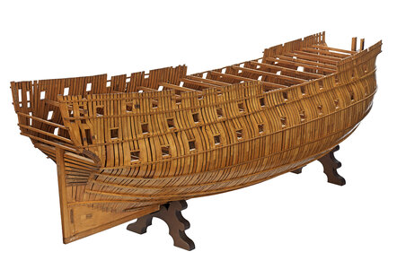

But you can see, that these last models are pure structural models, so the focus of the modeler was to show really the framing and the structure of the model - so they were educational models
Intrepid (1770); Warship; Third rate; 64 guns
Scale: 1:48. A contemporary full hull skeleton model of the Intrepid (1770), a third rate 64 gun two-decker ship of the line. Numerous hand written labels attached to inner and outer surfaces of frame identifying specific parts.The ‘Intrepid’ model was almost certainly the one referred to in the following letter from King George III to Lord Sandwich in September 1773: ‘I shall be very curious to receive the model you mean to send tomorrow, and doubt not from the ingenuity of Mr Williams that it will thoroughly explain the construction of a ship, which the more I reflect on it the more it shows the perfection to which mechanics has arrived.’
Coming now to available POF-kits on the market.
most of all POF-kits have a very simplified framing, single or double frames with the same width from floor to top (like the first group of contemporary models I showed.
The HMS Granado section model I showed is according my knowledge the only one available on the market with the try to make a 100% accurate and technically correct framing - with the disadvantage for the modeler, that the design and also the production of such kit elements takes a lot of developing time and also costs
The full hull Granado model (shown in this topic) is already one of the very rare kits, which are showing the reduction in the width of the frames. So not completely historical correct, especially in the area of the top timbers, but already much much better from the technical view, than most of all other POF-kits
So you can see, that it is a compromise, because hostorical correctness will rise the costs for a kit, and also not every modeler wants to have very complex frames to build. Also you will need much more working hours on the model for complex frames, compared to simplified frames
To summarize my point of view:
The Granado framing is some of the best you can get on the market, a compromise Yes, but very good.
And the frmaing of the kit is already more correct, than the famous Granado model in the museum.....
In view of this discrepancy, other than historical or academic interest, isn't the placement of limber holes pretty much up to the whim of the builder?
Everybody can decide, how he will build his model
Such discussions about some details are pure fun and because I am interested in these details.
Modelers often like to pimp their kit models to make them more detailed or more historical correct.
The kit manufacturer can not make all details (also a question of costs) so every individual modeler can add more details.
In the last section model, I made bolts and treenails, I added eyebolts, showed some joints of the planking, made some additional clamps and also the fishdavit
And the research for correct and detailed information, and also the discussion here with friends are the salt in the modeling soup.
At the end everybody is the lonely owner of his model, and can do what he likes or is able to do. With or without the limber holes.
Sorry for this very long post ...... hope nobody is bored ......
Hallo Nigel,Hi Uwe
I will tag along if I may.The framing on the full hull is obviously that way to keep production costs down.It couldn't really be done with laser and would require a multi axis mill.
If the upper works are fully planked,I would not be concerned.If I were leaving onside unplanked I may be tempted to replace the tops of these frames with scratch built ones.
Kind Regards
Nigel
I think, that I will plank both sides fully, so the top timbers will be not visible.
But refering your idea to change only the top timbers when unplanked: this will not so easily work, because then you have also to move or adjust the futtocks and the floor timbers (the vertical axis of the frames will be moved slightly fore or aft) ....... so means partly you have to change complete frames -> It is no so easy
Hallo Ed,
Many Thanks for your interest in the log, but also in the discussion, and also in your interest in POF-modeling.
Much appreciated
Usually the frame construction of POF-kits are much more simplified, either to make it slightly easier for the modeler, but also to reduce the costs for such kits.
But they follow mainly the way like usually used and executed also in contemporary models, which are available in museum.
These models are showing very simplified framing, usually double frames with the same thickness from the floor timber at the keel up to the top timbers
View attachment 299470 View attachment 299469
View attachment 299467
View attachment 299465 View attachment 299468
These models, and most of these models in the museum are like this, shall show the hull form, but have no focus on the framing structure
The well known Granado model has double and single frames, but the frames are not reduced in width or other complex framing, just double and single frames of the same width from floor to top
View attachment 299472
The following are already some models showing partly the reduction of the width in every frame
View attachment 299466
and a very small number also the distortion of the top timbers next or caused by gunports (like here the model of the HMS Intrepit (1770)
View attachment 299471 View attachment 299473
View attachment 299473
But you can see, that these last models are pure structural models, so the focus of the modeler was to show really the framing and the structure of the model - so they were educational models
Intrepid (1770); Warship; Third rate; 64 guns
Scale: 1:48. A contemporary full hull skeleton model of the Intrepid (1770), a third rate 64 gun two-decker ship of the line. Numerous hand written labels attached to inner and outer surfaces of frame identifying specific parts.
The ‘Intrepid’ model was almost certainly the one referred to in the following letter from King George III to Lord Sandwich in September 1773: ‘I shall be very curious to receive the model you mean to send tomorrow, and doubt not from the ingenuity of Mr Williams that it will thoroughly explain the construction of a ship, which the more I reflect on it the more it shows the perfection to which mechanics has arrived.’
Coming now to available POF-kits on the market.
most of all POF-kits have a very simplified framing, single or double frames with the same width from floor to top (like the first group of contemporary models I showed.
The HMS Granado section model I showed is according my knowledge the only one available on the market with the try to make a 100% accurate and technically correct framing - with the disadvantage for the modeler, that the design and also the production of such kit elements takes a lot of developing time and also costs
The full hull Granado model (shown in this topic) is already one of the very rare kits, which are showing the reduction in the width of the frames. So not completely historical correct, especially in the area of the top timbers, but already much much better from the technical view, than most of all other POF-kits
So you can see, that it is a compromise, because hostorical correctness will rise the costs for a kit, and also not every modeler wants to have very complex frames to build. Also you will need much more working hours on the model for complex frames, compared to simplified frames
To summarize my point of view:
The Granado framing is some of the best you can get on the market, a compromise Yes, but very good.
And the frmaing of the kit is already more correct, than the famous Granado model in the museum.....
Everybody can decide, how he will build his model
Such discussions about some details are pure fun and because I am interested in these details.
Modelers often like to pimp their kit models to make them more detailed or more historical correct.
The kit manufacturer can not make all details (also a question of costs) so every individual modeler can add more details.
In the last section model, I made bolts and treenails, I added eyebolts, showed some joints of the planking, made some additional clamps and also the fishdavit
And the research for correct and detailed information, and also the discussion here with friends are the salt in the modeling soup.
At the end everybody is the lonely owner of his model, and can do what he likes or is able to do. With or without the limber holes.
Sorry for this very long post ...... hope nobody is bored ......
A very nice exposition Uwe!
Granado's framing, although slightly simplified, is one of the details that attracted me to the kit.
I'd really like to get my hands on the cross section kit as well, but Tom doesn't appear to have it available at present - I would imagine all his time and effort is going in to the production of part three of Granado.
Anyone have the cross-section kit for sale?
Ted


