-

Win a Free Custom Engraved Brass Coin!!!
As a way to introduce our brass coins to the community, we will raffle off a free coin during the month of August. Follow link ABOVE for instructions for entering.
-

PRE-ORDER SHIPS IN SCALE TODAY!
The beloved Ships in Scale Magazine is back and charting a new course for 2026!
Discover new skills, new techniques, and new inspirations in every issue.
NOTE THAT OUR FIRST ISSUE WILL BE JAN/FEB 2026
You are using an out of date browser. It may not display this or other websites correctly.
You should upgrade or use an alternative browser.
You should upgrade or use an alternative browser.
HMS GRANADO - full hull - POF kit by CAF in 1:48 - by Uwe
slow and steady
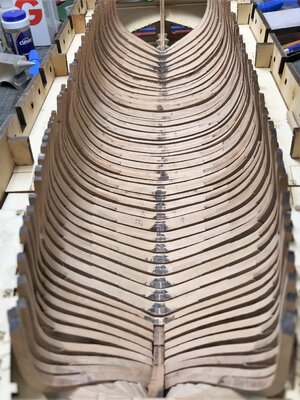
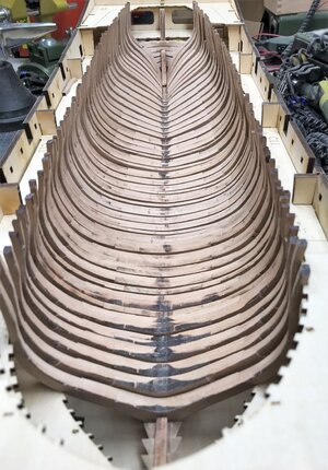
I decided to prepare further the frames, before I finaly prepare and fix the cant frames and transoms.....
So in moment I am making a lot of sanding-dust
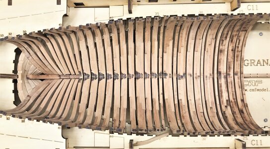
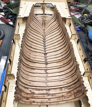
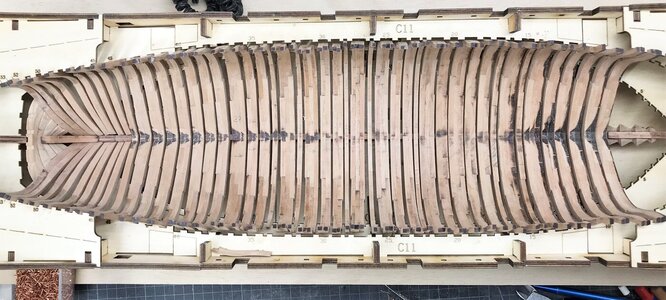
up to frame #37 they are already "handsanded", frames #23 to #36 are only sanded with the JET
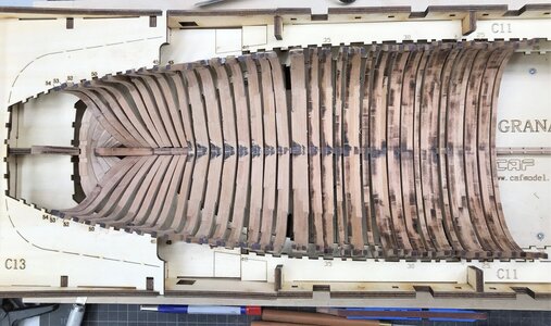
view direction to the stern
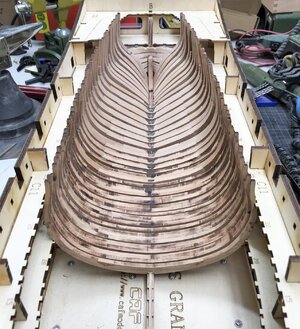
and towards the bow
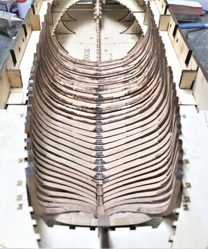
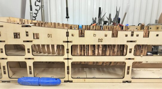
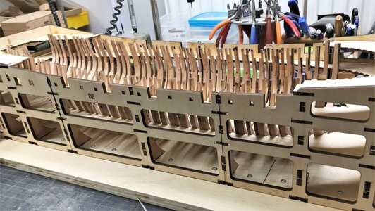
also the accurate location of each frame on the height has still to be fine-tuned
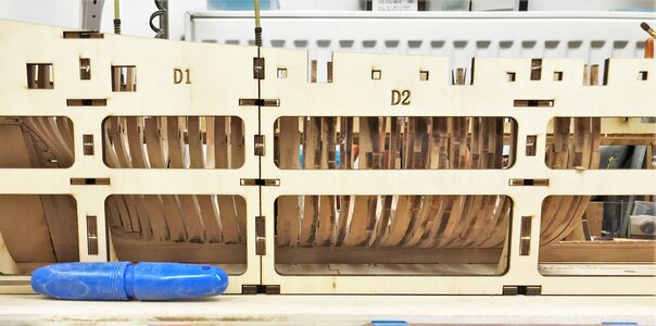
still a lot to do with the frames, but it is a good feeling to see step by step and frame by frame the growing of a ships hull
Many Thanks for your interest ..... to be continued
- Joined
- Dec 9, 2019
- Messages
- 961
- Points
- 403

Witaj
Bądź szczęśliwie zrobiłeś dużo dużoj pracy ,nie spiesz się.
Pozdrawiam Mirek
Hello
Be happy you did a lot of work, do not rush.
Greetings Mirek
Hallo Uwe, yes this sanding job is quite involved and lengthy. But your slowly growing frame collection looks really great and promises to be another one of your top works. Einfach saugut der Mann.
Who said it will be easy, and fast?It is still a lot of frames missing
Oh Ja - POF are never fast and often not easy -> these kits are the salt in the soupWho said it will be easy, and fast?
and I like it "salty"
To have a break during the partly boring pre-sanding, I decided to make also parallel the bolting of the frames.
I made the bolts in the for me usual method with copper nails - just thought about the new method introduced by Oliver, but I have not the patience in moment, so let us make the bolts "conventional" ..... with 50 nails per frame so in total also more than 2.000 "bolts"
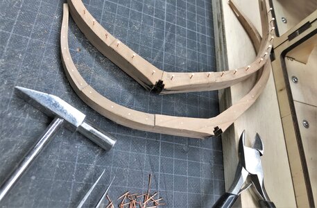
also the single frames the chocks have to be fixed with bolts
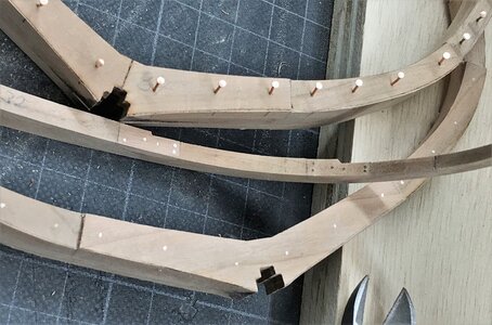
Due to the fact, that I still do not know which parts I will plank on outside or inside, I decided to make the bolting of the frames everywhere
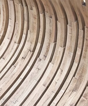
not really much is visible, but if you take a closer look - I know, that they are there - and we are building the models for ourself (and some interested modeling friends, like you all......
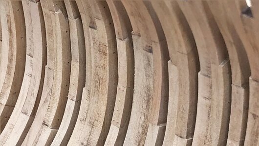
many Thanks for your interest .... to be continued .....
I made the bolts in the for me usual method with copper nails - just thought about the new method introduced by Oliver, but I have not the patience in moment, so let us make the bolts "conventional" ..... with 50 nails per frame so in total also more than 2.000 "bolts"

also the single frames the chocks have to be fixed with bolts

Due to the fact, that I still do not know which parts I will plank on outside or inside, I decided to make the bolting of the frames everywhere

not really much is visible, but if you take a closer look - I know, that they are there - and we are building the models for ourself (and some interested modeling friends, like you all......

many Thanks for your interest .... to be continued .....
To have a break during the partly boring pre-sanding, I decided to make also parallel the bolting of the frames.
I made the bolts in the for me usual method with copper nails - just thought about the new method introduced by Oliver, but I have not the patience in moment, so let us make the bolts "conventional" ..... with 50 nails per frame so in total also more than 2.000 "bolts"
View attachment 302678
also the single frames the chocks have to be fixed with bolts
View attachment 302679
Due to the fact, that I still do not know which parts I will plank on outside or inside, I decided to make the bolting of the frames everywhere
View attachment 302680
not really much is visible, but if you take a closer look - I know, that they are there - and we are building the models for ourself (and some interested modeling friends, like you all......
View attachment 302681
many Thanks for your interest .... to be continued .....
Nice work Uwe!
I decided early on that I would not pin the frames fore and aft, but that I would pin the joints outside and in - this will be done when out of the jig.
As you rightly say - it is up to each modeller to decide how much detail to show. I did fully pin 'King's Fisher', but now she's finished, you can barely make out the pinning anyway!
Ted
Great start Uwe, looking very good! 
Hallo Ted,Nice work Uwe!
I decided early on that I would not pin the frames fore and aft, but that I would pin the joints outside and in - this will be done when out of the jig.
As you rightly say - it is up to each modeller to decide how much detail to show. I did fully pin 'King's Fisher', but now she's finished, you can barely make out the pinning anyway!
Ted
a very good point.
I just checked your (btw amazing) Kingfisher model -
I hope, that due to the fact that the space between the frames is getting bigger to the top, these aft and fore bolting is visible at ther upper half of the frames. and especially in the area at the bow and stern and not midships.
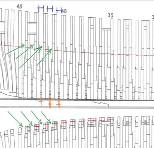
You are coming along very nicely, looks great, Uwe, fast and furious.
Knight head and hawse pieces are next to be prepared. and afterwards the cant frames.
Only when these are fixed the square frames can be installed.
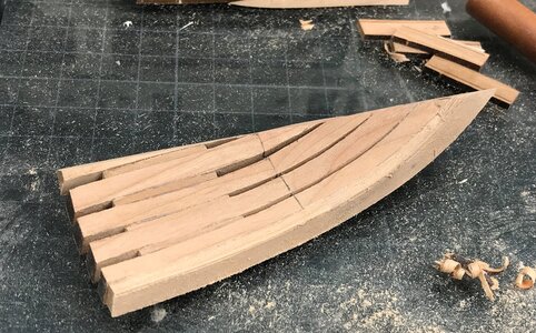
The elements for both sides are prepared - at the top you can see the temporary jigs (plywood) for the haswe pieces segment
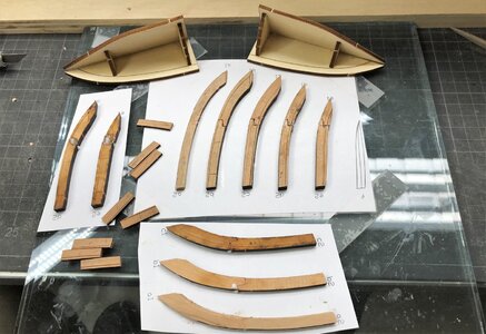
The elements "a" and "f" are cnc milled, all the others laser cut
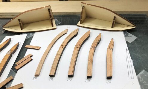
the pieces are pre sanded with my JET
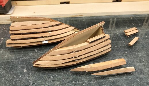
the right segment is already fixed with glue, the thickness of the distance elements between the hawse pieces have to be sanded in order to get the correct angles
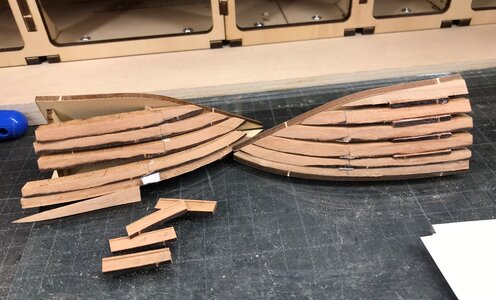
hand sanded in the jig
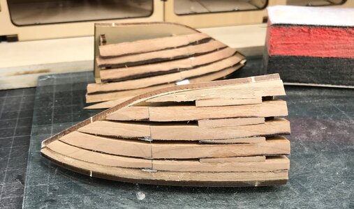
for removing out of the jig I had to destroy the plywood
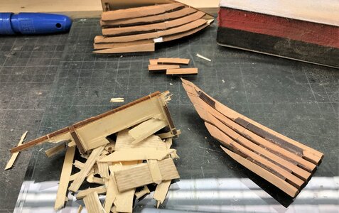
coming close to the final form - when the complete hull is finished and out of the main jig the final form will be prepared
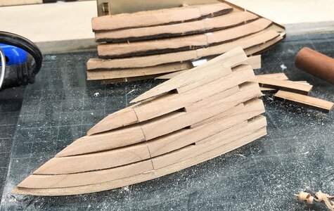
and the same from inside
now the other side has to be prepared .... so to be continued
Many Thanks for your interest - see you soon
Only when these are fixed the square frames can be installed.

The elements for both sides are prepared - at the top you can see the temporary jigs (plywood) for the haswe pieces segment

The elements "a" and "f" are cnc milled, all the others laser cut

the pieces are pre sanded with my JET

the right segment is already fixed with glue, the thickness of the distance elements between the hawse pieces have to be sanded in order to get the correct angles

hand sanded in the jig

for removing out of the jig I had to destroy the plywood

coming close to the final form - when the complete hull is finished and out of the main jig the final form will be prepared

and the same from inside

now the other side has to be prepared .... so to be continued
Many Thanks for your interest - see you soon
- Joined
- Sep 3, 2021
- Messages
- 5,190
- Points
- 738

And here I thought I had it bad with my Bluenose bow pieces... Nice job!Knight head and hawse pieces are next to be prepared. and afterwards the cant frames.
Only when these are fixed the square frames can be installed.
View attachment 304140
The elements for both sides are prepared - at the top you can see the temporary jigs (plywood) for the haswe pieces segment
View attachment 304129
The elements "a" and "f" are cnc milled, all the others laser cut
View attachment 304130
the pieces are pre sanded with my JET
View attachment 304131
the right segment is already fixed with glue, the thickness of the distance elements between the hawse pieces have to be sanded in order to get the correct angles
View attachment 304132
hand sanded in the jig
View attachment 304133
for removing out of the jig I had to destroy the plywood
View attachment 304134
coming close to the final form - when the complete hull is finished and out of the main jig the final form will be prepared
View attachment 304135
and the same from inside
View attachment 304136
now the other side has to be prepared .... so to be continued
Many Thanks for your interest - see you soon
Very good work and beautifully and extremely clearly and understandably presented. Bravo.
Many Thanks for your kind words and also all the likes received - much appreciated
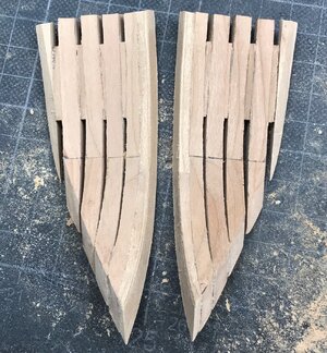
The other side was also done in the same way
On the left still in the jig
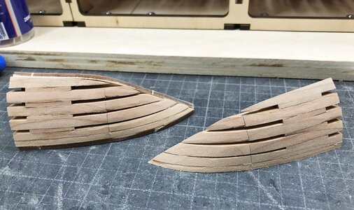
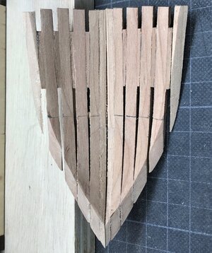
now we have the time to see the whole truth - are the two sides symetrical ?!? - they have to be
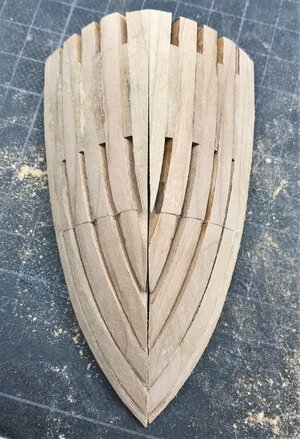
only the keel is missing in between, but this would be the view to the bow
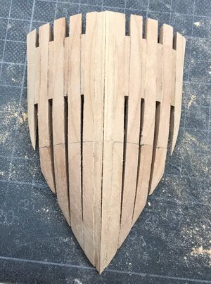
and inside?
first check in the jig
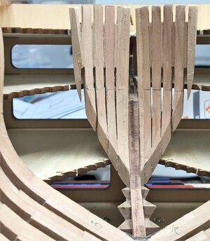
Many Thanks for your interest in my work and building log of my HMS Granado ..... to be continued with the cant frames #1 to #7
The other side was also done in the same way
On the left still in the jig

now we have the time to see the whole truth - are the two sides symetrical ?!? - they have to be

only the keel is missing in between, but this would be the view to the bow

and inside?


first check in the jig

Many Thanks for your interest in my work and building log of my HMS Granado ..... to be continued with the cant frames #1 to #7
- Joined
- Apr 20, 2020
- Messages
- 6,241
- Points
- 738

it's looks great workMany Thanks for your kind words and also all the likes received - much appreciated
The other side was also done in the same way
On the left still in the jig
View attachment 304245
now we have the time to see the whole truth - are the two sides symetrical ?!? - they have to be
View attachment 304246
only the keel is missing in between, but this would be the view to the bow
View attachment 304247
and inside?
View attachment 304248
View attachment 304250
first check in the jig
View attachment 304249
Many Thanks for your interest in my work and building log of my HMS Granado ..... to be continued with the cant frames #1 to #7
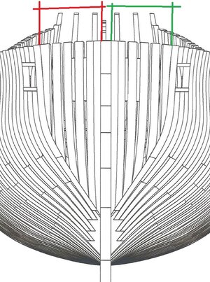
The next and last missing frames are the cant frames at the bow
the laser lines for the sanding are fitting very well - also in principle the frames by themself into the jig
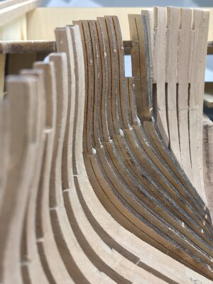
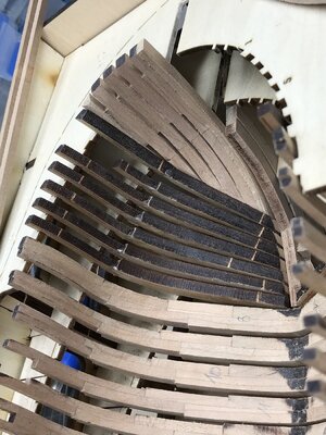
step by step I am getting ready, so I can start to fix the elements permanently on the keel
Many Thanks for your interest .... to be continued ....
the laser lines for the sanding are fitting very well - also in principle the frames by themself into the jig


step by step I am getting ready, so I can start to fix the elements permanently on the keel
Many Thanks for your interest .... to be continued ....


