HMS GRANADO - full hull - POF kit by CAF in 1:48 - by Uwe

Hi Uwe,
I think you have previously drilled bolt holes by hand. Is that what you did this time as well (and with amazing speed I might add)? Do your bolts go 'through and through' or are they added on each side individually? (Have started to think through for myself what it would be like to build a POF kit.) Thank you.
Hallo Paul,
you remember correctly, that in the past I killed the drills very often and used usually the hand drill.
On the frames of this model I tried once more a lighter Proxxon drill with a 0,5mm drill and it worked. Ok - all holes were drilled vertically down, so no real challenge.
I was happy about this, due to the fact, that I have 52 bolts per frame, with each side 26 - all together appr. 2.000 nails (and holes) on single, double, triple frames

So to answer your question also complete
the bolts are no going trough, I am pretty sure, that this would not work correctly, minimum the pattern on the side were the drill would come out, would be not accurate enough.

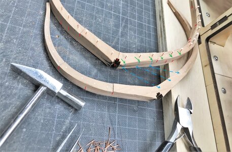
IMG_0118b.jpg


Taking a look at the frame in the photo:
The red lines are marking the butt joints of the individual parts of the frame, like floor timber, futtocks and top timber. (a bolt would be never installed through a butt joint)
So I marked on one side of the frame the more or less correct bolting pattern like on a real ship frame (shown in books of Lavery, Goodwin etc.)
I drill ed on this side the holes, installed the nails and sanded them down.
Having the location of the bolt, I transfered (by eye) the location rectangle to the outside of the frame (green arrows are showing the points and made a small mark with a pencil
Than I turned the frame 180° and by eye I marked appr. the location of the bolts (blue dashed arrows)
with this I have appr. the same location and definitely the same number of bolts

When the model is finished you will be never able to see both sides of the same frame, so it is not important looking at one frame, but if you look later at the hull alongside you will see the sides of the frames.
So it is important to make the bolts on all the frames with the same pattern

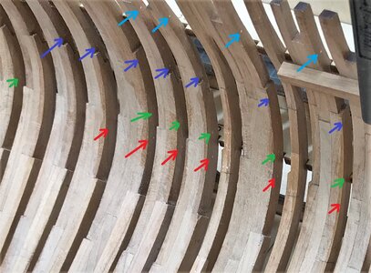
I tried to show this here, where I marked the bolts (visible in the photo) with different colours - if the pattern would be irregular it would be easily visible.

IMG_0253a.jpg

btw: the single frames have no bolts at the sides of the frames, only the chocks are bolted with 6 bolts per chock

It is not a must to do it like I did it - it was at the time I made the bolts important for me personally - at the end I will know, if this additional work was really necessary
f.e. you can see that I made also bolts at the floor timbers - these will be never visible later on -> but I (and you also) know, that they are there

Many Thanks for your kind interest
 
It is not a must to do it like I did it - it was at the time I made the bolts important for me personally - at the end I will know, if this additional work was really necessary
f.e. you can see that I made also bolts at the floor timbers - these will be never visible later on -> but I (and you also) know, that they are there
I've seen various methods and materials being applied to simulate bolts or treenails or whatever you might want to call them.
After some trials, I opted for hand-drilled holes and toothpicks for bolts. The result is that the bolts are visible, but just so, you have to know what to look for.
If I ever consider to build another model, I most definitely will revisit the topic "frame bolts".
I am looking forward how your bolts will look, once you've applied finish to your frames. Right now they're looking great. Thumbsup
 
Last edited:
Hallo Paul,
you remember correctly, that in the past I killed the drills very often and used usually the hand drill.
On the frames of this model I tried once more a lighter Proxxon drill with a 0,5mm drill and it worked. Ok - all holes were drilled vertically down, so no real challenge.
I was happy about this, due to the fact, that I have 52 bolts per frame, with each side 26 - all together appr. 2.000 nails (and holes) on single, double, triple frames

So to answer your question also complete
the bolts are no going trough, I am pretty sure, that this would not work correctly, minimum the pattern on the side were the drill would come out, would be not accurate enough.

View attachment 308197


Taking a look at the frame in the photo:
The red lines are marking the butt joints of the individual parts of the frame, like floor timber, futtocks and top timber. (a bolt would be never installed through a butt joint)
So I marked on one side of the frame the more or less correct bolting pattern like on a real ship frame (shown in books of Lavery, Goodwin etc.)
I drill ed on this side the holes, installed the nails and sanded them down.
Having the location of the bolt, I transfered (by eye) the location rectangle to the outside of the frame (green arrows are showing the points and made a small mark with a pencil
Than I turned the frame 180° and by eye I marked appr. the location of the bolts (blue dashed arrows)
with this I have appr. the same location and definitely the same number of bolts

When the model is finished you will be never able to see both sides of the same frame, so it is not important looking at one frame, but if you look later at the hull alongside you will see the sides of the frames.
So it is important to make the bolts on all the frames with the same pattern

I tried to show this here, where I marked the bolts (visible in the photo) with different colours - if the pattern would be irregular it would be easily visible.

View attachment 308209

btw: the single frames have no bolts at the sides of the frames, only the chocks are bolted with 6 bolts per chock

It is not a must to do it like I did it - it was at the time I made the bolts important for me personally - at the end I will know, if this additional work was really necessary
f.e. you can see that I made also bolts at the floor timbers - these will be never visible later on -> but I (and you also) know, that they are there

Many Thanks for your kind interest
Bookmarked with my humble thanks.
 
Question - how much tolerance is built into the frames to remove the char ? Thanks Uwe !
Do you refer to the frames........ I think you should not be affraid too much about to remove too much

Especially for the frames the char will be removed on most of the frames due to the fact, that you bevell / fair already the frame to get the correct shape / cross section of the frame timbers

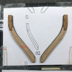
IMG_0180.jpg

red is the final cross section after fairing,
green is the removed sanded area
and blue is the area where you find the char of the laser cut

So you can see, that with fairing the green parts away, also the char is removed

IMG_0145a.jpg

Only midship frames have no or minimal fairing necessary, but here you can wait with most char removal actions until you finally sand the complete hull - and than it is most important, that you get a smooth surface and a correct shape of all frames together.
Final sanding I do everytime after all frames are fixed and you can sand the complete hull , so that you sanding block is touching several frames in the same move.

and to be honest - if there is some micrometer mistake and the frames are no following the "official" lines of the ships hull - nobody can see this
important in my opinion is, that you not feel it, if your fingers are moving over the frames to check the correct shape of the hull (and not single frames)
 
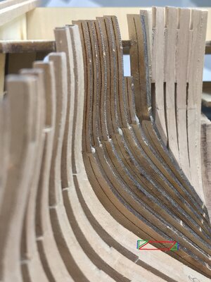
Just remembered a nice photo of my last build, which is showing very well the most important thing in my opinion.

The unplanked frames should show the continuous lines of the ship - the smooth surface of the hull

IMG-9204.jpg

 
Going further - after fixing the cant frames at the stern also the cant frames at the bow are finaly adjusted and fixed permanently to the keel

IMG_0245.jpg

IMG_0246.jpg

IMG_0247.jpg

Afterwards it will be time to fix all the "normal" frames in between - when all frames are fixed, the inner hul has to be finetuned and sanded

Many Thanks for your interest
 
Many Thanks for your kind commenst and the interest in my project.
also for all the likes received ........

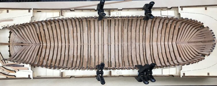
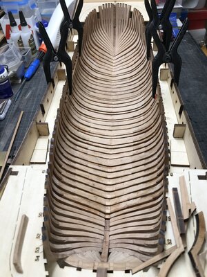
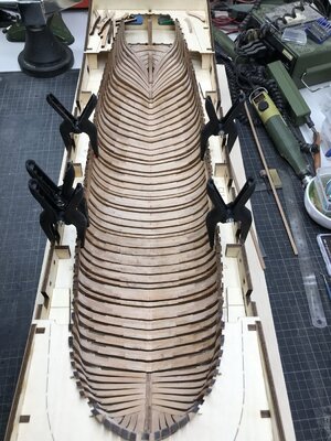
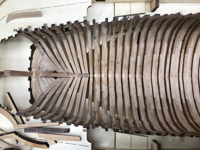
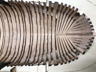
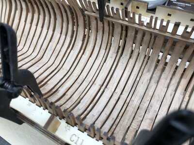
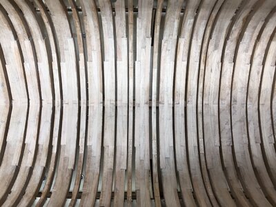
In the meantime all the frames are finally fixed on the keel, so it is time for the inner sanding.
But before making a lot of wooden dust I made some photos of the status

IMG_0248.jpg

IMG_0249.jpg

IMG_0250.jpg

IMG_0252.jpg

IMG_0251.jpg

IMG_0253.jpg

IMG_0254.jpg

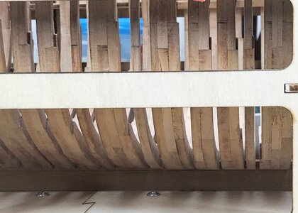
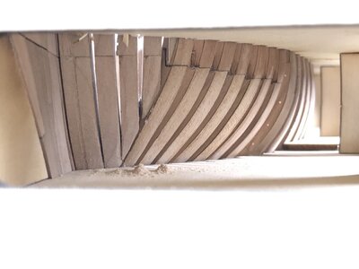
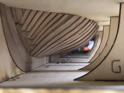
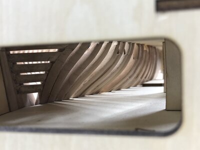
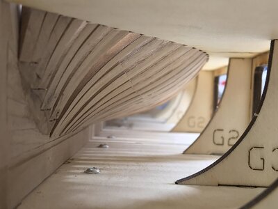
and some nice views through the windows of the jig

IMG_0255.jpg

The bow

IMG_0261.jpg

IMG_0263.jpg

and also the stern

IMG_0256.jpg

IMG_0258.jpg


If there is enough place in my car, I am thinking about bringing the Granado also to Augsburg......
 
Many Thanks for your kind commenst and the interest in my project.
also for all the likes received ........

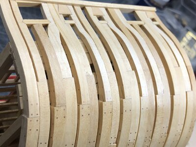
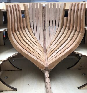
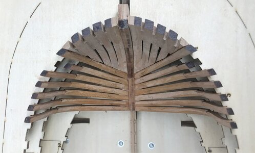
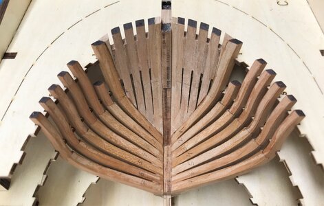
In the meantime all the frames are finally fixed on the keel, so it is time for the inner sanding.
But before making a lot of wooden dust I made some photos of the status

View attachment 309909

View attachment 309910

View attachment 309911

View attachment 309913

View attachment 309912

View attachment 309914

View attachment 309915

and some nice views through the windows of the jig

View attachment 309916

The bow

View attachment 309919

View attachment 309920

and also the stern

View attachment 309921

View attachment 309917


If there is enough place in my car, I am thinking about bringing the Granado also to Augsburg......
That’s a impressive amount of frames, Uwe. With a beautiful fit. I have my mask on, let the dust flow around! :) Or use the vacuum cleaner ……. ;)
Rergards, Peter
 
Many Thanks for your kind commenst and the interest in my project.
also for all the likes received ........

In the meantime all the frames are finally fixed on the keel, so it is time for the inner sanding.
But before making a lot of wooden dust I made some photos of the status

View attachment 309909

View attachment 309910

View attachment 309911

View attachment 309913

View attachment 309912

View attachment 309914

View attachment 309915

and some nice views through the windows of the jig

View attachment 309916

The bow

View attachment 309919

View attachment 309920

and also the stern

View attachment 309921

View attachment 309917


If there is enough place in my car, I am thinking about bringing the Granado also to Augsburg......
Nice going, Uwe!
I found the frame tops wandered around a bit, so glued a sacrificial strip to the outside of the hull at the top of the frames. This pulled the frames in to a lovely alignment, and after all, it's the outside that has to line up perfectly - you can easily sand the inner face of the frames to suit.

Ted

Ted
 
Many Thanks for your kind commenst and the interest in my project.
also for all the likes received ........

In the meantime all the frames are finally fixed on the keel, so it is time for the inner sanding.
But before making a lot of wooden dust I made some photos of the status

View attachment 309909

View attachment 309910

View attachment 309911

View attachment 309913

View attachment 309912

View attachment 309914

View attachment 309915

and some nice views through the windows of the jig

View attachment 309916

The bow

View attachment 309919

View attachment 309920

and also the stern

View attachment 309921

View attachment 309917


If there is enough place in my car, I am thinking about bringing the Granado also to Augsburg......
I get dizzy looking at so many frames at once. Great work Uwe, I especially like the 'underwater level' photography Thumbsup
 
Many Thanks for all your nice comments due to the fact, that it is making fun working with this kit, I am making good progress working regular every day one or two hours on the model - in the meantime already some 150 hours ...... and I am enjoying them

Nice going, Uwe!
I found the frame tops wandered around a bit, so glued a sacrificial strip to the outside of the hull at the top of the frames. This pulled the frames in to a lovely alignment, and after all, it's the outside that has to line up perfectly - you can easily sand the inner face of the frames to suit.

Ted

Ted

Good point Ted,
yes the temporary strip at the outside of the top timbers is already shown in the beginning of stage / part 2 of the kit.
I have to say that most of the tops of the frames are really in line where they should be, only a handfull especially midships are 1 or 2mm narrower / more narrow than they should be
So for the final final inner sanding before fixing f.e. the keelson elements I have to fix temporary such stripes like you mentioned in your comment.
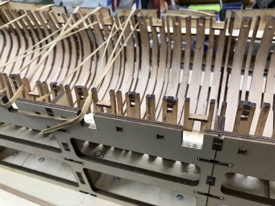
In the meantime I started to fix the top elements of the oars sweep prts and also the sills of the gunports, and here I made before a temporary "rubber-band fixing" which you will se in one of the next photos.

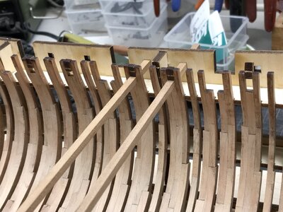
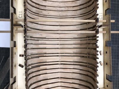
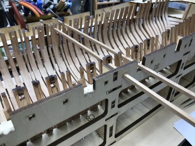
In order to get the sweep ports in the correct level there are some rectangular holes in the jig-walls - with using such wooden strips (included in kit) the correct height can be realised.

IMG_0264.jpg


IMG_0265.jpg

Such strips are also used for leveling the lower points of the gunport sills - herefore you see also the bigger square notches in the jig walls

IMG_0266.jpg

a very clever idea to secure the correct height either of all sweep ports and the gunports

Now here you can see my temporary "holding back the frame tops rubber bands" during the installation of the horizontal sills of the gunports, which are connecting two partner frames

IMG_0267.jpg

Many Thanks for your interest in my building log - to be continued .....

BTW: When there is enough space in the trunk of my car, I am maybe taking also the Granado with me to the Augsburg meeting on next Saturday ..... so everybody participating can inspect the frames -I hope to get constructive critcism and tipps

See you here or in Augsburg
 
Back
Top