-

Win a Free Custom Engraved Brass Coin!!!
As a way to introduce our brass coins to the community, we will raffle off a free coin during the month of August. Follow link ABOVE for instructions for entering.
-

PRE-ORDER SHIPS IN SCALE TODAY!
The beloved Ships in Scale Magazine is back and charting a new course for 2026!
Discover new skills, new techniques, and new inspirations in every issue.
NOTE THAT OUR FIRST ISSUE WILL BE JAN/FEB 2026
You are using an out of date browser. It may not display this or other websites correctly.
You should upgrade or use an alternative browser.
You should upgrade or use an alternative browser.
HMS GRANADO - full hull - POF kit by CAF in 1:48 - by Uwe
Looks absolutely great, Uwe.
Great looking work Uwek.
Bill
Bill
- Joined
- Dec 9, 2019
- Messages
- 970
- Points
- 403

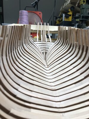
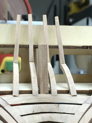
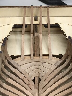
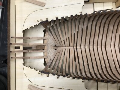
Pięknie pięknie i tyle Pozdrawiam Mireki ostatnie belki konstrukcji rufy
View attachment 312668
View attachment 312669
naprawdę bardzo pomocne jest posiadanie takiego przyrządu - więc wszystkie belki są przymocowane we właściwym miejscu i pod odpowiednim kątem
View attachment 312670
View attachment 312671
View attachment 312672
View attachment 312673
Wielkie dzięki za zainteresowanie, otrzymane komentarze i uwagi oraz wszystkie otrzymane polubienia - bardzo cenne
ciąg dalszy nastąpi.....
Beautifully beautiful and that's it. Regards Mirek
Last edited by a moderator:
First of all many thanks to all for the kind words and comments
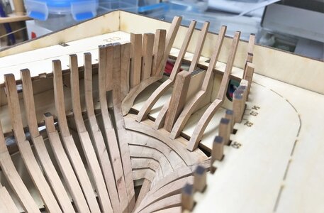
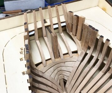
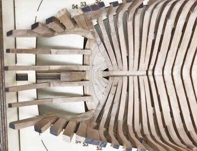
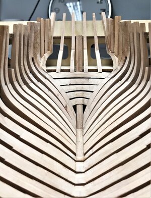
I was in the beginning of preparing the frames checking the / my possibilities to use the way the kit is prepared. But I came to the conclusion for me, that the result will be not satisfying myself. Therefore I decided to prepare all the frames in the conventional way and cut / split the hull later on, I guess directly under the wales.
Somehow in the way it was done by @Maarten on his model. But to make here a final decision I have to wait to get also part III of the kit, so I am able to complete the complete deck structure in order to get it riggid / stiff as possible with all knees, carlings and beams.
The execution of the interior, walls and the structure of the mortars has to wait until the deck is cut away...... this is the actual plan...... let us see
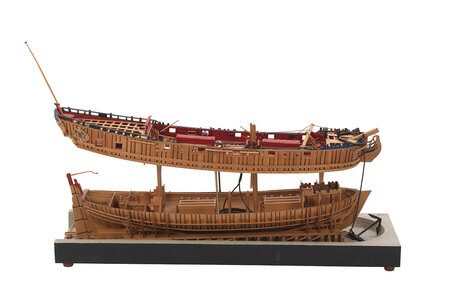
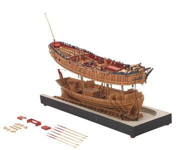
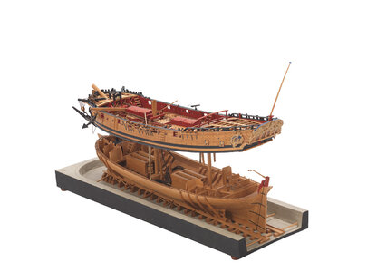
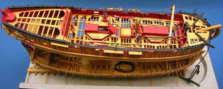
but definitely in moment I plan to make my model similar to the NMM-model
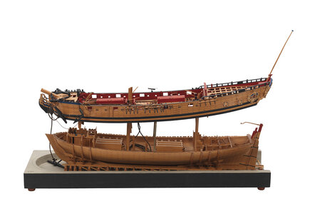
Hallo Daniel,Hi Uwek, will you split the ship using Tom's design, or cut it straight or just do nothing at all.
Daniel
I was in the beginning of preparing the frames checking the / my possibilities to use the way the kit is prepared. But I came to the conclusion for me, that the result will be not satisfying myself. Therefore I decided to prepare all the frames in the conventional way and cut / split the hull later on, I guess directly under the wales.
Somehow in the way it was done by @Maarten on his model. But to make here a final decision I have to wait to get also part III of the kit, so I am able to complete the complete deck structure in order to get it riggid / stiff as possible with all knees, carlings and beams.
The execution of the interior, walls and the structure of the mortars has to wait until the deck is cut away...... this is the actual plan...... let us see
but definitely in moment I plan to make my model similar to the NMM-model


Good evening Uwe. Spent some time catching up here. I didn’t want to send a hundred likes. Totally out of my league- I echo all the compliments you have deserved. Brilliant. Cheers GrantFirst of all many thanks to all for the kind words and comments
Hallo Daniel,
I was in the beginning of preparing the frames checking the / my possibilities to use the way the kit is prepared. But I came to the conclusion for me, that the result will be not satisfying myself. Therefore I decided to prepare all the frames in the conventional way and cut / split the hull later on, I guess directly under the wales.
Somehow in the way it was done by @Maarten on his model. But to make here a final decision I have to wait to get also part III of the kit, so I am able to complete the complete deck structure in order to get it riggid / stiff as possible with all knees, carlings and beams.
The execution of the interior, walls and the structure of the mortars has to wait until the deck is cut away...... this is the actual plan...... let us see
but definitely in moment I plan to make my model similar to the NMM-model
View attachment 312799 View attachment 312800
View attachment 312801 View attachment 312802
View attachment 312798
Hi Uwek,
Closely following your log - cant wait to start after the Bismarck is completed. I will plank fully one side and have exposed frames on the other - no split hull although its tempting. I will have to substitute the lamintated keel parts which shouldnt be to much work. Look forward to seeing your progress continue.
Closely following your log - cant wait to start after the Bismarck is completed. I will plank fully one side and have exposed frames on the other - no split hull although its tempting. I will have to substitute the lamintated keel parts which shouldnt be to much work. Look forward to seeing your progress continue.
Starting with section II of the kit
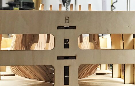
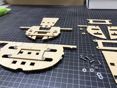
One of the first working steps are preparing of the temporary templates which are necessary / hepful also for the correct levels of the deck clamps, which have to be installed in one of the next steps
All together four of these templates have to be prepared - here template 1 and 2 finished and parts of 3 on the right side
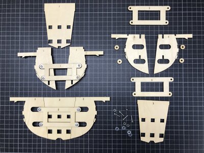
all four templates prepared
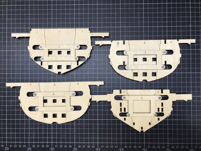
on each side you can see the notches for the correct height of the deck clamps
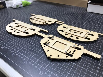
the six square holes in the center part will be used later on for the correct height of the mortar structure beams
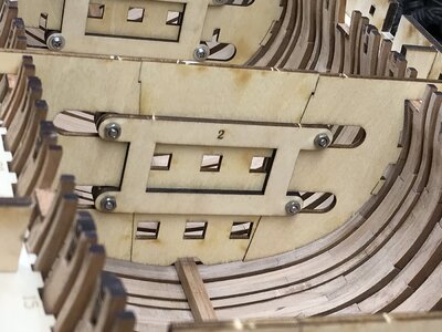
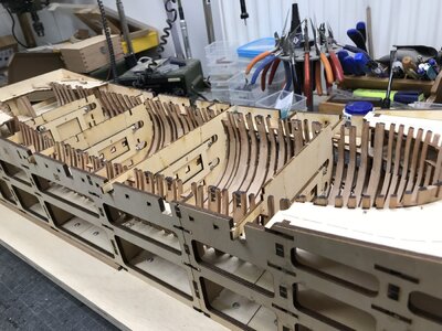
A very clever idea - so this time no need to use the laser to mark the heights ......
Many Thanks for your interest ..... to be continued .....
One of the first working steps are preparing of the temporary templates which are necessary / hepful also for the correct levels of the deck clamps, which have to be installed in one of the next steps
All together four of these templates have to be prepared - here template 1 and 2 finished and parts of 3 on the right side


all four templates prepared

on each side you can see the notches for the correct height of the deck clamps

the six square holes in the center part will be used later on for the correct height of the mortar structure beams


A very clever idea - so this time no need to use the laser to mark the heights ......
Many Thanks for your interest ..... to be continued .....
Very interesting construction, the center piece with the long holes can be adjusted and if so, for what purpose.Starting with section II of the kit
One of the first working steps are preparing of the temporary templates which are necessary / hepful also for the correct levels of the deck clamps, which have to be installed in one of the next steps
All together four of these templates have to be prepared - here template 1 and 2 finished and parts of 3 on the right side
View attachment 313016
View attachment 313017
all four templates prepared
View attachment 313018
on each side you can see the notches for the correct height of the deck clamps
View attachment 313019
the six square holes in the center part will be used later on for the correct height of the mortar structure beams
View attachment 313021
View attachment 313020
A very clever idea - so this time no need to use the laser to mark the heights ......
Many Thanks for your interest ..... to be continued .....
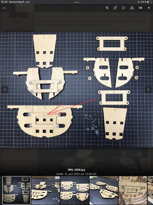
Without this movable center part it would be hard to install the templates inside the hull without damaging the templateVery interesting construction, the center piece with the long holes can be adjusted and if so, for what purpose.
These templates are to be installed at the gunports
The upper width if the hull is smaller than on the height of the waterline
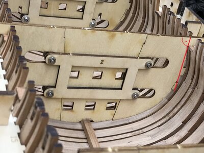
red markings are the width at the gunports - orange the width where the beam clamps have to be installed
at template 1 I marked the movements with arrows
1) bringing the template inside the hull without the middle part, until it is laying on top of the sills of the gunports - with a reduced width of the template
2) when it is at the correct height inside the hull move both sideparts until they have contact with the frame (green arrows)
3) the last will be pushing down the center part so you have rigged and stiff template fitting well inside the frame
4) to remove the template you have to remove first the center part - otherwise it is not possible
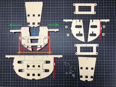
Without this movable center part it would be hard to install the templates inside the hull without damaging the template
These templates are to be installed at the gunports
The upper width if the hull is smaller than on the height of the waterline
View attachment 313026
red markings are the width at the gunports - orange the width where the beam clamps have to be installed
at template 1 I marked the movements with arrows
1) bringing the template inside the hull without the middle part, until it is laying on top of the sills of the gunports - with a reduced width of the template
2) when it is at the correct height inside the hull move both sideparts until they have contact with the frame (green arrows)
3) the last will be pushing down the center part so you have rigged and stiff template fitting well inside the frame
4) to remove the template you have to remove first the center part - otherwise it is not possible
View attachment 313027
Uwek, you are really making our life easier when the time will come to assemble this kit. All these details .... Thank you !!!
Daniel
Thanks Uwe, extremely helpful and very descriptive. Avery thoughtful auxiliary design.
- Joined
- Oct 15, 2017
- Messages
- 1,191
- Points
- 443

Wow, a very interesting design and approach to achieving consistent results for modelers. Thanks for sharing Uwe.Starting with section II of the kit
One of the first working steps are preparing of the temporary templates which are necessary / hepful also for the correct levels of the deck clamps, which have to be installed in one of the next steps
All together four of these templates have to be prepared - here template 1 and 2 finished and parts of 3 on the right side
View attachment 313016
View attachment 313017
all four templates prepared
View attachment 313018
on each side you can see the notches for the correct height of the deck clamps
View attachment 313019
the six square holes in the center part will be used later on for the correct height of the mortar structure beams
View attachment 313021
View attachment 313020
A very clever idea - so this time no need to use the laser to mark the heights ......
Many Thanks for your interest ..... to be continued .....
In order to make the next working steps, it was time to fianly fix the keelson on the frames.
Some small adjustments at the hook scarf joints, but al together the elements of the keeson fitted very good
- I used the standard copper bolts to "fix" the keelson with the frames, and tried to follow the technically correct bolting pattern shown in deverse books like Goodwin and Lavery
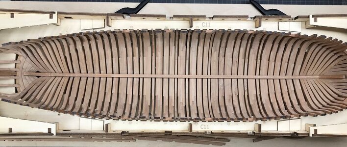
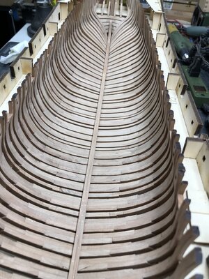
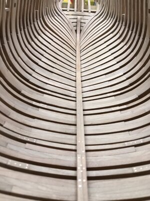
Many Thanks for you kind interest in my building log - happy to get comments (also critics, negative and positive)
to be continued .....
Some small adjustments at the hook scarf joints, but al together the elements of the keeson fitted very good
- I used the standard copper bolts to "fix" the keelson with the frames, and tried to follow the technically correct bolting pattern shown in deverse books like Goodwin and Lavery


Many Thanks for you kind interest in my building log - happy to get comments (also critics, negative and positive)
to be continued .....


