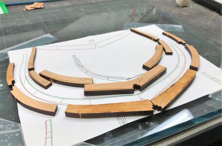
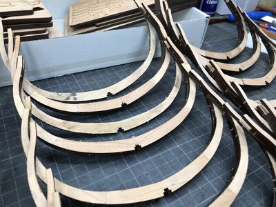
HMS GRANADO - full hull - POF kit by CAF in 1:48 - by Uwe

Uwek

Administrator
Staff member
Administrator
Forum Moderator
Joined
Dec 25, 2017
Messages
33,166
Points
1,238

Location
Vienna, Austria
Hallo friends......

how to start the building log ?

1) starting with the section model which I finalized short time ago?
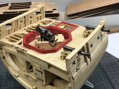
IMG_0031.jpg


This I will show also later on when I compare the framing etc. of the section with the full hull model - also the wood material, the jig etc.......
And you can not really compare the two kits, which have so much differences


or .....

2)
to start with the expected result?

I hope once the model will have the quality like the model built in 1971 by Lightley, Robert A. and owned now by the NMM
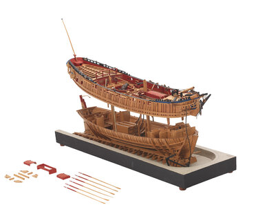
l5780_003.jpg


OK - I will not be able to reach this quality, but I try everything to get close from a certain distance ;)


or

3)
I start with the Kit Review(s), which I made before, showing the content of the kit(s) very much in detail


or

4)
The Granado History with all contemporary drawings and models known


or

5)
the available and intesively used Anatomy of Ships book about the bomb vessel HMS Granado (1742) by Peter Goodwin


or

6) in medias res -
making a first frame ...... Let us make some saw dust


you see, that we have already so much information here in our forum about the ship, the kit and the results of some research, which should be not repeated

I will choose possibility 6 !!!
 
The available five chairs in my workshop are taken, so everybody else coming later has to stand, but I guess it will be not so crowded. Or use also a drone

And like you know my person, I am often try to show slightly more, so that somebody else building the same model can follow, get some hints and tipps, but also maybe not to make the same mistakes like myself - I hope it will not get boring.......

Before starting really with the wood, we have to take a look at the "types" of frames we have here in the full hull model.
I think it will be interesting to know also the differences between the full hull and the section model

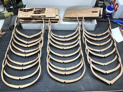
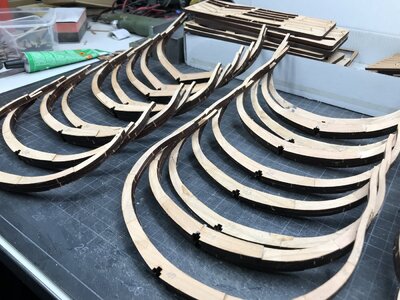
In the beginning I am producing the complete frames (no half frames) from axis 8 to axis 45

longitudinal - frames.JPG

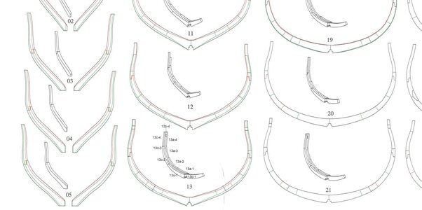
every single frame is shown in scale and details on a drawing - the parts of each frame can be identified in the manual, so no problem to find the correct element of the frame and the correct location - the modeler should be only organized and remove only the parts of the individual frame needed just in moment, because the wooden parts are not numbered - identification only via the manual -> so do not mix it up

this is an excerpt of the frame drawing sheet

frames drawing.JPG

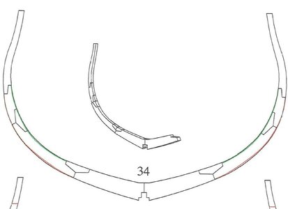
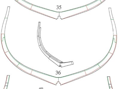
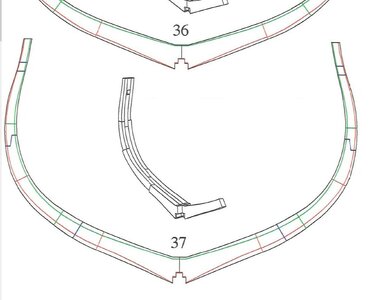
In principle we have three different types of frames

single frame with chocks

frame 34.JPG

double frame

frame 36.JPG

and triple frames (usually at the sweep ports for the oars)

frame 37.JPG

Many Thanks for your interest already at the beginning .... to be continued
 
Many Thanks for all your positive comment and feedbacks - and also all the lieks recieved

Now let us make the first / one frame
and do not be afraid -> I will not show all 57 frames ....... only some of them ;)

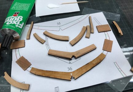
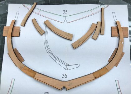
These are the typical elements of one of the double frames, here frame 36, which was also shown (drawing) in my yesterdays post
- half side is labeled with "a" and the other side with "b" - logical
you can also see, that the floor timber and the two first futtocks have the biggest thickness with 5mm, the other futtocks have 4mm and the top timbers have 3mm
- not on every frame, but on most of them
also you can see the laser marks for the later bevelling of each frame

IMG_0009.jpg

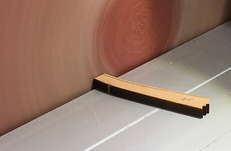
before fixing the elements together I carefully sanded the butt joint areas with my sander - with this also 90° assured

IMG_0010.jpg

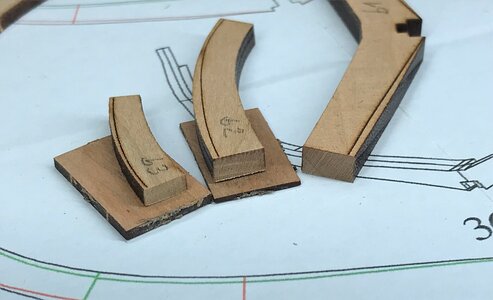
included in the kit are also 4 times 1mm and 4 times 2mm pad elements, which compensate the difference of thickness (3, 4 and 5mm) of the frame elements

IMG_0011.jpg

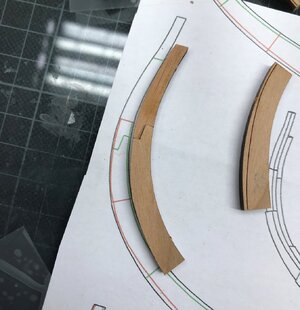
before gluing the flat scarf joint have to be prepared - only small adjustments are necessary, but definitely the laser char has to be removed

IMG_0013.jpg

all work preparation for frame 36 is done -all materials are prepared
- toothpick with white wood glue
- fixogum glue to fix the frmae elements on top of the frame drawing paper copy
- frame drawing is fixed on a glass, so I have definitely a plane and leveled base
- the four pad elements are ready
- all frame elements are pre sanded with the circular sander
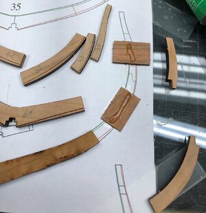
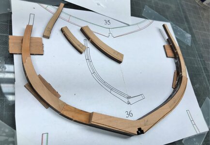
=> here the two first futtocks of "a" are already glued together and fixed with fixogum on top of the drawing

IMG_0015.jpg

the two pads are fixed on top of the paper and have already a worm of fixogum for the next frame elements (futtock and top timber of "a")

IMG_0016.jpg

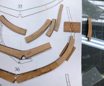
second futtock is fixed

IMG_0017.jpg

and finally the top timber

IMG_0018.jpg

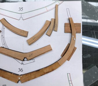
the other side of "a" is now also prepared and the floor timber of "b" is sitting on top of "a"

IMG_0019.jpg

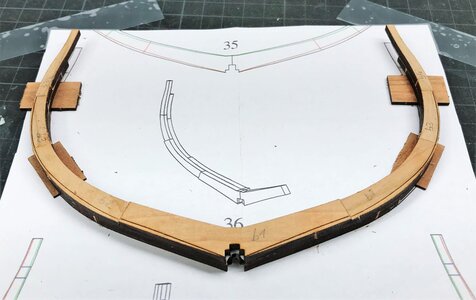
futtock and top timber of "b" is now fixed - good to see are now the different thicknesses of the elements

IMG_0020.jpg

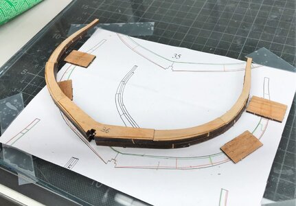
frame 36 is now complete

IMG_0021.jpg

IMG_0027.jpg
 
Last edited:
Many Thanks for all your positive comment and feedbacks - and also all the lieks recieved

Now let us make the first / one frame
and do not be afraid -> I will not show all 57 frames ....... only some of them ;)

These are the typical elements of one of the double frames, here frame 36, which was also shown (drawing) in my yesterdays post
- half side is labeled with "a" and the other side with "b" - logical
you can also see, that the floor timber and the two first futtocks have the biggest thickness with 5mm, the other futtocks have 4mm and the top timbers have 3mm
- not on every frame, but on most of them
also you can see the laser marks for the later bevelling of each frame

View attachment 298359

before fixing the elements together I carefully sanded the butt joint areas with my sander - with this also 90° assured

View attachment 298360

included in the kit are also 4 times 1mm and 4 times 2mm pad elements, which compensate the difference of thickness (3, 4 and 5mm) of the frame elements

View attachment 298361

before gluing the flat scarf joint have to be prepared - only small adjustments are necessary, but definitely the laser char has to be removed

View attachment 298362

all work preparation for frame 36 is done -all materials are prepared
- toothpick with white wood glue
- fixogum glue to fix the frmae elements on top of the frame drawing paper copy
- frame drawing is fixed on a glass, so I have definitely a plane and leveled base
- the four pad elements are ready
- all frame elements are pre sanded with the circular sander
=> here the two first futtocks of "a" are already glued together and fixed with fixogum on top of the drawing

View attachment 298363

the two pads are fixed on top of the paper and have already a worm of fixogum for the next frame elements (futtock and top timber of "a")

View attachment 298364

second futtock is fixed

View attachment 298365

and finally the top timber

View attachment 298366

the other side of "a" is now also prepared and the floor timber of "b" is sitting on top of "a"

View attachment 298367

futtock and top timber of "b" is now fixed - good to see are now the different thicknesses of the elements

View attachment 298368

frame 36 is now complete

View attachment 298369

View attachment 298374
Good evening Uwe. I ask; Are the holes for the passage of water between the frames not drawn on the canvases? Thank you "scuppers in the hold "
 
Many Thanks for your interest in my work and the building log of the HMS Granado

Do you fixogum the pads to the drawings as well as the futtocks?

Yes - when the pads are also fixed to the paper, so the small necessary adjustments / movements during positioning of the parts are going easier, when the pads are not moving. Afterwards the rubber cement and rest of paper can be removed from the wood easily by rubbing with the fingertips.
Important is, that the thickness of the glue shall not be too much , so some pressure is necessary to reduce the thickness. the pad plus the two layers of fixogum-rubber cement should be the 1mm thick

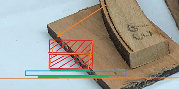
I try to show this sandwich in the small sketch (without scale)

Unbenannt100.JPG

red are the two wooden frame elements, yellow between is wood glue
under it in green fixgum layer - in blue the pad and under it in green the base layer of fixogum, orange is the drawing
so the two green fixogum layers plus the blue pad should have a thickness of 1mm or 2mm
BTW: at the frame elements I marked in orange the later beveling, which are marked with a laser mark on the farme elements

Do you weigh down the frames they are drying?

I am using a wood glue, called "Ponal Express" which is fix already after some minutes, so during the installation with fresh glue I press them with the fingers down, with this the thickness of wood glue between the two wooden parts is reduces as much as possible. and usually the glue is starting already to get adhesive.
In the beginning with the first frames I put some small iron elements / cubes on top, slightly probelematic, because you have on top of the frame also the steps by 1 or 2mm - later on with other frames I did not put any weights on top - the same result.......
So I guess it should be tried, because it will depend on the glue you use....
I can remove the finished frmaes already after 5 to 10 minutes from the drawing
 
Good evening Uwe. I ask; Are the holes for the passage of water between the frames not drawn on the canvases? Thank you "scuppers in the hold "
Hallo,
many thanks for your interest in my building log and the model / kit

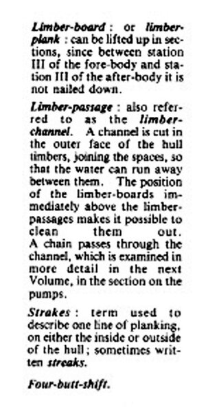
I guess you mean the so called "limber passage" or "limber channel"

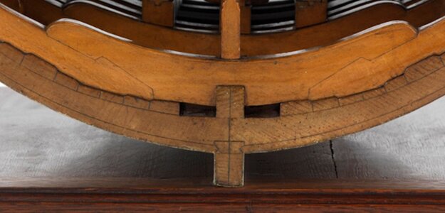
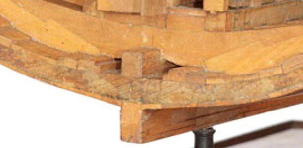
let us take first a view on the existing contemporary model available

Unbenannt25.JPG

Unbenannt26.JPG

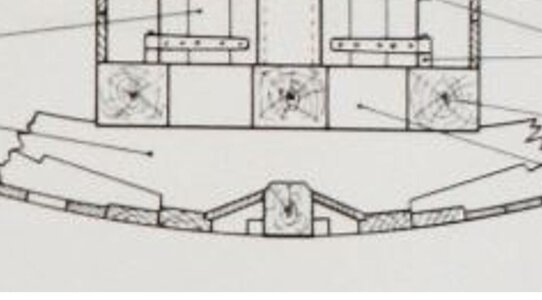
Here is shown the limber passage only on top of the frames, but no channel at the outer side of the frames between frames and the outer planking

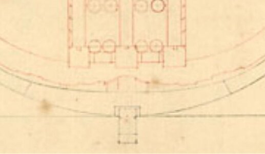
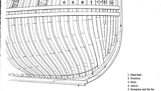
The same at the contemporary drawing of a similar english bomb vessel - the two small rectangel lines on the left and right side of the keel can not be a limber passage, because otherwise the keel would be not fixed enough. They would be not so high

Unbenannt27.JPG

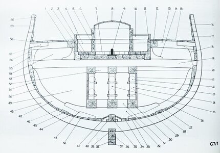
Theis the cross section drawing from the Anatomy book by Peter Goodwin - here cleary the channel is shown on top of the frames on left and right side of the keelson

IMG-8025a.jpg

Unbenannt28.JPG

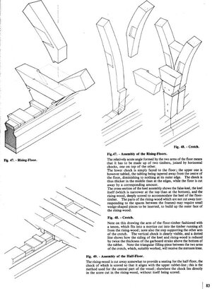
I know, that on french ships they had a real channel notched into the outer side of the frames and covered by the outer planking - here they used also a long chain along this passage in order to clean the passage - following excerpts are from the 74-gun ship by Jean Boudriot

Unbenannt30.JPG

Unbenannt29.JPG

Unbenannt31.JPG

I have to check also once more other books by Lavery and Goodwin describing the english way of the limber passage only to get a clear final knowledge

But for now:
If it is only left and right of the keelson, than there is no need to cut the frames - here only later on the riders have to get some notches
and I have the feeling in moment, that the english ships had only these and not often the lower passage

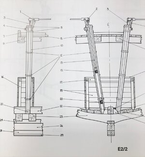
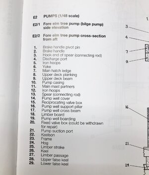
When we take a look at the pumps it is also underling this opinion, because the pump suction port is on top of the frame

IMG-8912.jpg IMG-8913.jpg

If there would be also the limber passage like shown in the sketches of the 74 gun ship, I would cut the notches at the time, when the complete framing is fixed on the keel and everything stabilised. than I will mark the location of this channel notches over the complete length of the ship - at this stage it can be done much more accurate and following a smoothe curved line like shown by Jean Boudriot on the sketch with the bow
 
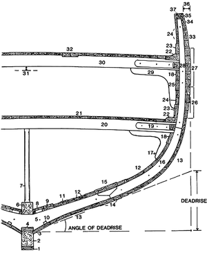
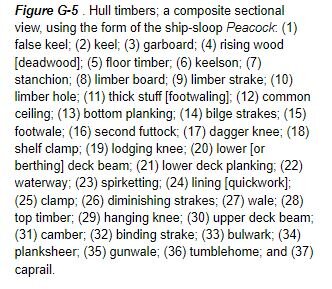
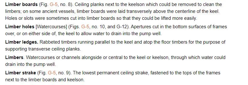
Here I found such a limber hole "10"

oxfordhb-9780199336005-graphic207-full.gif

limber hole.JPG

limber.JPG

from Illustrated Glossary of Ship and Boat Terms


but as mentioned before - I would do this earliest, when all frames are fixed
 
Here I found such a limber hole "10"

View attachment 298547

View attachment 298548

View attachment 298549

from Illustrated Glossary of Ship and Boat Terms


but as mentioned before - I would do this earliest, when all frames are fixed
Hello Uwe, Thank you for answering me, I appreciate you very much for your analysis, forgive me if I do not answer you on the matter due to translation problems, I will also do research on this particular, my observation is, how does bilge water collect where the pumps are?Well done
 
Back
Top