-

Win a Free Custom Engraved Brass Coin!!!
As a way to introduce our brass coins to the community, we will raffle off a free coin during the month of August. Follow link ABOVE for instructions for entering.
-

PRE-ORDER SHIPS IN SCALE TODAY!
The beloved Ships in Scale Magazine is back and charting a new course for 2026!
Discover new skills, new techniques, and new inspirations in every issue.
NOTE THAT OUR FIRST ISSUE WILL BE JAN/FEB 2026
You are using an out of date browser. It may not display this or other websites correctly.
You should upgrade or use an alternative browser.
You should upgrade or use an alternative browser.
HMS Ontario 1780 scale 1:32 POB full version
- Thread starter zoly99sask
- Start date
- Watchers 81
-
- Tags
- ontario sloop-brig
- Joined
- Aug 10, 2017
- Messages
- 1,706
- Points
- 538

Hi Greg,
The original drawing Admiralty Draught of 1780 does not waterlines on the lines plan. It looks like John McKay used the body and sheer plans to develop a lines plan, if so it should not make a lot of difference how the bulkheads were drawn.
Zoly received the bulkhead drawing from someone else and I don’t know how they were drawn. I agree with you, using line drawings is the best way to develop bulkheads and frames.
Hi Zoltan,
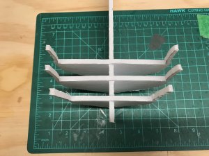
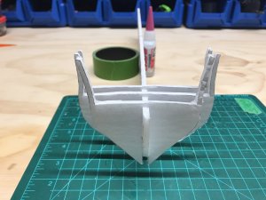
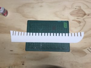
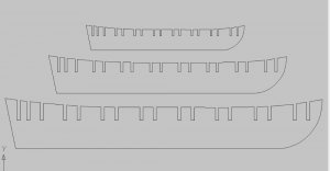
It looks like the problem is with the slots in the center board, they are too deep, assuming you will be adding a keel assembly to the bottom of the center board align the aft side of the bulkheads with the bottom of the centerboard and add shims at the top of the bulkheads. Check the inboard profile, the slots in the first three bulkheads run parallel to the top of the centerboard, if this doesn’t fix the problem we can try something else.
Try using a box cutter with a heavy-duty blade to cut the project board, I think you will find it cuts a lot faster than a hobby knife.
Mike
- Joined
- Aug 10, 2017
- Messages
- 1,706
- Points
- 538

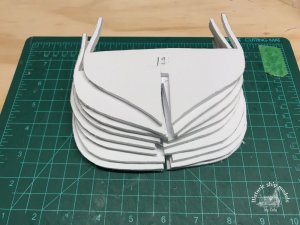
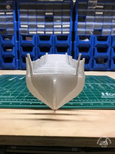
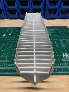
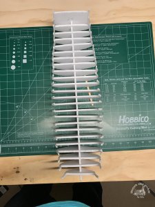
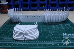
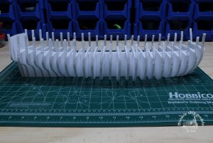
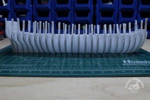
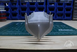
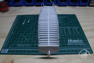
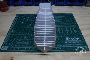
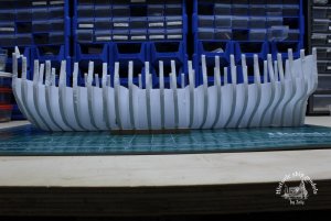
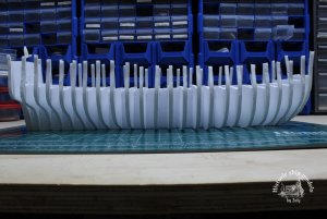
It looks like you corrected the problem with the first three frames.Hello Mike,The boxcutter did not perform well,so I am still using the x-acto blade an I am still cutting too.
It looks like you corrected the problem with the first three frames.
Not sure about that ,the first bulkhead seems too high,lets see when I have finished all of them.
- Joined
- Dec 1, 2016
- Messages
- 6,383
- Points
- 728

I do not want to high jack your topic
I thought I might inject my way of creating a set of bulkheads
first step is to trace the original plan keep in mind the original plans are not always drawn accurate and there might be distortion, that is delt with later.
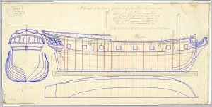
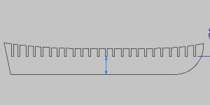
first line is to establish the bottom of the slot for the bulkheads, this can be at any height

I thought I might inject my way of creating a set of bulkheads
first step is to trace the original plan keep in mind the original plans are not always drawn accurate and there might be distortion, that is delt with later.

first line is to establish the bottom of the slot for the bulkheads, this can be at any height

- Joined
- Dec 1, 2016
- Messages
- 6,383
- Points
- 728

first step in drawing a set of bulkheads is to create a base line in this case it is the line at the bottom which happens to be to top of the rabbit or where the bottom of the bulkheads stop. I will now copy the shape from the bodyplan over and establish the height of the cap rail, deck and bottom of the slot. You can not just adjust the slot because that will throw off the deck and sheer (height of the cap rail) the slot, the deck and sheer line all are in relation to one another.
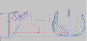
here with bulkhead number 2 I set the heights of the slot and the deck but notice I extended the caprail line (sheer line) I personally do this because I want to leave extra at the top. I will set my sheer when all the bulkheads are in place. The sheer gives a hull that flowing line and I like to do that when I have the hull shape set first.
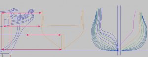
working in CAD I can use "ortho" on or off what this does is allow me to draw and move things at 90 degrees or straight. In this example I moved bulkhead straight across to the right to make sure it falls in the proper place within the bodyplan. My bulkhead is NOT a dead match to the original line that was drawn in the bodyplan. This is because when I draw a curved line in CAD I am using a "spline" what that does is it creates a smooth curve from point to point. The original line might of been drawn either by hand or the use of a set of ship curves at any rate it is the hand of man and not a computer aided drawing.
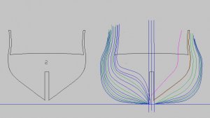
Here is a big issue with CAD for some reason when you take a drawing from say AutoCAD and export it and then import it into another drawing program or convert it to another format some of the lines and commands do not convert accurately. So when I plot out my bulkheads they are plotted directly from AutoCAD or turbocad or what ever program I drew them in.

here with bulkhead number 2 I set the heights of the slot and the deck but notice I extended the caprail line (sheer line) I personally do this because I want to leave extra at the top. I will set my sheer when all the bulkheads are in place. The sheer gives a hull that flowing line and I like to do that when I have the hull shape set first.

working in CAD I can use "ortho" on or off what this does is allow me to draw and move things at 90 degrees or straight. In this example I moved bulkhead straight across to the right to make sure it falls in the proper place within the bodyplan. My bulkhead is NOT a dead match to the original line that was drawn in the bodyplan. This is because when I draw a curved line in CAD I am using a "spline" what that does is it creates a smooth curve from point to point. The original line might of been drawn either by hand or the use of a set of ship curves at any rate it is the hand of man and not a computer aided drawing.

Here is a big issue with CAD for some reason when you take a drawing from say AutoCAD and export it and then import it into another drawing program or convert it to another format some of the lines and commands do not convert accurately. So when I plot out my bulkheads they are plotted directly from AutoCAD or turbocad or what ever program I drew them in.
Last edited:
Hi Dave,thanks for your input and help,feel free to contribute any time really appreciated.I am still not finished with the bulkheads ,I will more info and images later this week.
- Joined
- Dec 1, 2016
- Messages
- 6,383
- Points
- 728

as you can see in the original drawing the half breadth plan " the hull line plan" has no hull lines all there is the sheer line, the deck line and the floorhead "rising line"
I always work from the bodyplan
this is something that started with Harold Underhill when he described "picking " off the shape of the frames from the half breadth plan. That will work IF you have a set of hull lines but in early drawings the hull lines or shape of the hull was rarely included. I can go deep into lifting frame and or bulkhead shapes from plans but that is another topic on its own. Just like the misuse of the term "lofting" I see it used as drawing the shape of frames. Lofting is a term that refers to taking an established frame shape and from that shape creating a full scale set patterns.
so anyhow back to the Ontario topic sorry for the high jacking.
oh one more thing without the original CAD drawing there is no way to correct or reset the bulkheads. you got to know the measurements.
Last edited:
- Joined
- Dec 1, 2016
- Messages
- 6,383
- Points
- 728

ships were not built from plans the frame patterns were drawn from an offset chart. I was thinking why not do the same here so here goes
first draw a box around the bulkhead
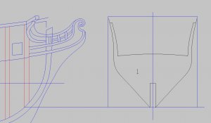
doing it by the numbers bulkhead sits in the yellow location on the profile to the left
all the measurements are taken from the cad drawing
red arrows is the size of the box 4.000 at 1/4 scale OR 6.000 at 3/8 scale
arrow color 1/4 scale 3/8 scale
green 3.901 5.851
yellow 3.764 5.646
blue 2.291 3.436
purple 1.014 1.611
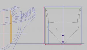
you do not have to work it down to 0.000 rounding out is fine all the above measurement work out as long as the bottom of the slots are
1.783 at 1/4 scale and 2.694 at 3/8 scale from the bottom up
I would suggest a set of calipers they are not that expensive you just dial in the measurements
first draw a box around the bulkhead

doing it by the numbers bulkhead sits in the yellow location on the profile to the left
all the measurements are taken from the cad drawing
red arrows is the size of the box 4.000 at 1/4 scale OR 6.000 at 3/8 scale
arrow color 1/4 scale 3/8 scale
green 3.901 5.851
yellow 3.764 5.646
blue 2.291 3.436
purple 1.014 1.611

you do not have to work it down to 0.000 rounding out is fine all the above measurement work out as long as the bottom of the slots are
1.783 at 1/4 scale and 2.694 at 3/8 scale from the bottom up

I would suggest a set of calipers they are not that expensive you just dial in the measurements
- Joined
- Dec 1, 2016
- Messages
- 6,383
- Points
- 728

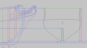
lets play around with bulkhead number 2
the bottom dark blue line is the top of the rabbit
so from that line up the little blue arrow line is 0.196 so that is where the bottom of the bulkhead sits and all the light blue lines should line up at the top of the notch, at the deck and the sheer line at the top
checking the location from the light blue line at the bottom the top of the notch is 1.592 deck is 2.635 and at the top sheer line 4.119 the light green line is 4.427 these are at 1/4 inch = 1 foot scale if you are working in 3/8 scale each number is X 1.5

Thanks Dave ,this was very informative.
Zoltan
Zoltan
G'day Zoly
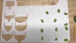
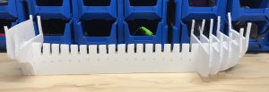
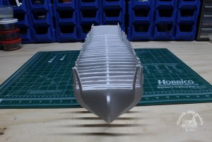
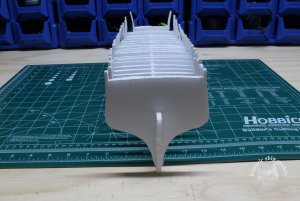
Most of the BH looks great, I have to agree with you about BH2 is too wide, I say about 10% or so. But I still think BH1 is on the big size as will, may be 15%or so.
Havagooday
Greg
Most of the BH looks great, I have to agree with you about BH2 is too wide, I say about 10% or so. But I still think BH1 is on the big size as will, may be 15%or so.
Havagooday
Greg
Very interesting. I wish I knew CAD. 
So do I Don, so do I.Very interesting. I wish I knew CAD.
Greg
Hi Zoltan,
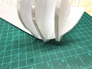
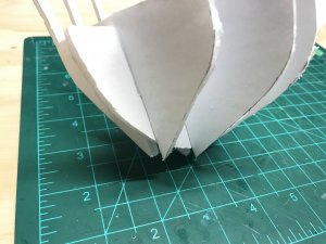
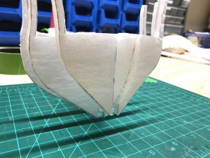
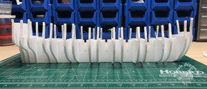
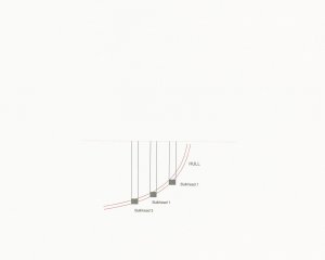
It looks like the first 4 frames are too narrow at the top and need additional material on the inboard side, see sketch.
Mike
yes Mike they need more thickness for bevelling,but some somehow they are not the right shape, maybe after beveling those bulkheads.

