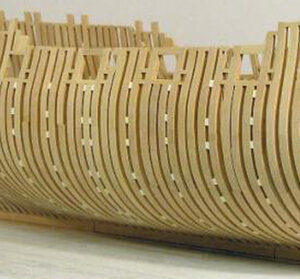
HMS Psyche drawings

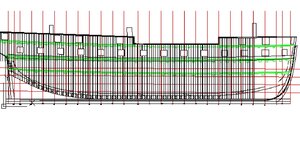
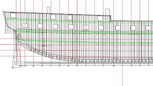
Taking a break from the inboard plan, and working on the body plan and framing plan.
The framing plan helps to show how the frames are layed out , with the room and space. I haven't quite got that figured out right now.


i was thinking about the framing plan and i figured all the frames are pre cut so you have to use extisting timbers, the easiest thing to do is pair up the frames.
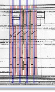
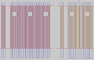
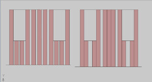
On the left is what shows up on the original single frame drawing, to the right is shifting the 2 frames under the ports out and shifting the frame between the ports to the center creating a tripple frame. There are an odd number of frames and there is no room between ports to add another frame to make 2 doubles.

it would make a very unique framing on the hull one of a kind.
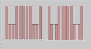
P FRAME.JPG


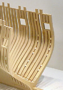
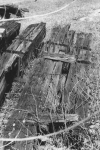
it is not that you would be making up a framing system the double frame then a tripple frame and back to a double was a systen used on the lakes as you can see by these timbers.
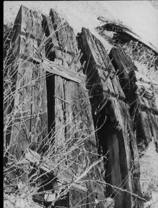
a2.jpg

a12.jpg
 
What I find of interest is, at the station line marked with an X, is the start of the dead flats. To the left the next station line is a dead flat and to the right is another station line as dead flats. For a total of over 10' of dead flats.
The right hand dead flat marked as (A) is were the triple frames are located. This I be-leave, sets up the rotation from the floors being on the right hand side of the double frame to the left hand side.
Pardon me but paint is doing a lousy job of reproducing my screenshots, I haven't figured out how yet to get a good image but can't be copied.


I would say you are correct Dave S. about the double framing using what was sent from England but there are too many frames needed for the amount sent.
I also referred to walkers and Nadine Kopps articles on the Charlotte. Using the premise that when they built the Psyche they probably didn't vary their building practices much. So both articles state that very little spacing was evident between frames. 1.5" to be exact.
The image I have is not very good but I reproduced the fore frame from the triple frames at 1.5" spacing. You will note that the gun ports do line up, not perfectly but close.
From the X deadflat to the stern way more of a challenge. 1.5' did not even come close. When I started to increase the room and space it got better. At 3" spacing it lined up to the ports better. Room and space went from 25 1/2"fore to 27" in the aft.
In the stern I extended the double frames with the spacing up to the station line 20 and then like charlottes examination I used single frames. All of this alomg the rising deadwood.
There are no cant frames at all in the stern. I am up to the cant frames however in the fore area.
frames.jpg
 
The framing above is an idea I had. It was based on the archeological survey done of the Charlotte.
Now that you mention it I never took into account the frames sent from England. But I don't know how many or how few of those frames actually arrived in Kingston.
The contract with the Bateaux captain didn't mention the exact number.
I will look at the framing style of more spacing between frames based on the port placements.
But there are more areas where triple frames are used and this was one of the problems I had originally. This is why I asked for any information about those x's. There are 4 more towards the stern and another 2 at the stem area.

I am progressing right now on the body plan. I am redrawing and completeing incomplete framesor putting in missing ones. The waterlines would be next and once those are complete I would proceed to the half breadth plan.
 
From the X deadflat to the stern way more of a challenge. 1.5' did not even come close. When I started to increase the room and space it got better. At 3" spacing it lined up to the ports better. Room and space went from 25 1/2"fore to 27" in the aft.


i see what your saying a space of 1.5" does not work. Keeping in mind the width of the frames are set you can not change them that is how they were sent. so if you double up the frames at the ports with a 2 inch space you end up with a wide gap between the ports like the drawing. You would have to increase the space between the frames by around 5 inches ( just a guess) to fill in the gap. you can add filler timber in the space but then you would have a solid wall of timber between the frames. i think the double and tripple frame might be how Bell and Strickland built the hull.

P4a FRAME.jpg
 
maybe the hull was built as designed with single frames. The more i try to reconfigure the framing to double frames the harder it is to work out. you can not add wood to the frames to make them wider nor would those guys resaw all that timber to make the frame smaller to fit more frames in. All you can do is shift the frames

it is logical to me if the hull was sent as a kit and all the framing timbers were pre cut it would be easy to just assemble the hull as designed.
 
No I can't believe like you said they would add filler frames for bigger gaps. Use what you have and speed is essential.
Also the other drawing is "as built", and there are triple frames so building as it was sent is out. But just a thought single frames between the triples. Larger gap but could work. But no evidence this is what they did. Past building practices show otherwise.
With the amount of triple frames it certainly looks like it could be solid walls or close to.
What I like about aurocad is the ability to undo or simply not save what you have done and continue a new idea.
 
In your picture if you increase the size of the gap under the ports to 3" this moves the frames so the 5" gap is smaller but also you may only have to cut the frame on ether side of the port off instead of notching it.
I like this idea better. simplier.
 
looking at the admiralty drawing it shows single frames 12 inches wide with a 5 inch space. it is marked 2 single frames make up one complete frame

P6a FRAME.jpg

on the left this is how the hull is designed

if you shift the 2 frames under the posts to make a double and shift the 2 frames between the posts to make the frames on either side of the posts you are left with one single frame with a wide space on both sides. so you can make an entire new frame and make that single a double, but the question is why bother?

i would think Bell and Strictland may very well have built the Psyche as designed with single fir frames. That would be the quickest way as apposed to trying to shift frames or add frames. Keeping in mind all these frame timbers are pre cut and shaped for their location in the hull so changing anything is a major operation.


P5a FRAME.jpg
 
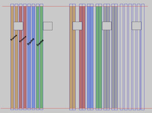
I am just wondering, On the original admiralty drawing there are 8 single frames. But Bell wrote across 2 of those frames to make a single double frame.
Look at it simply. Is he keeping the outside frame on the port there and just sliding the other frame up to it. Bolting those 2 together. Leaving a big gap under the port. Do the same for the next frame. etc. In other words, make just double frames on ether side of the ports and leave a big gap in the center .
Don't try to fill it in.
As you said use what you have, don't make any new.
I am not very good at explaining but look at your right hand picture. You drew the port with a single butting the port, space and then a double frame under, space and then a double to the next side of the port.
What I am saying is make a double next to the port, avery big space and then another double on the side of the port.
I will look into that
 
I am not very good at explaining but look at your right hand picture. You drew the port with a single butting the port, space and then a double frame under, space and then a double to the next side of the port.

actually that single is a double i just did not draw the other half in. The left post would look like the port on the right

On the original admiralty drawing there are 8 single frames. But Bell wrote across 2 of those frames to make a single double frame.

how do we know Bell wrote FRAME maybe that was on the original drawing


What I am saying is make a double next to the port, avery big space and then another double on the side of the port.
I will look into that

that is what i did here and that would leave a 10 inch gap in the hull under every port i think that is way to wide for a fir built hull.

P FRAME.JPG
 
if Bell wrote FRAME across 2 frames to make a double you will end up with uneven spacing and you can not shift the frames to even out the spacing without changing the location of the posts. so i think the word FRAME was on the original for some reason or another

P7a FRAME.jpg
 
This was the type of problem I was having doing room and space at 1.5".
Very difficult to make.
Maybe your right. They went back to original framing.
I just assumed, the the plans show changes and framing was added at same time.
 
The location is at station (A) going towards the stem. Because it was sent as an giant erector set the words framing, was just to show the direction of assembly.Floor first followed by 1st futtock. It could be that simple. it waas added at time of the original draft was made.
 
Ok, So if I go back to the original drawings, There is a 5" hog, rising wood on top of the keel. I would say if they used the original framing, the floors would be made to this 5" and so would the 1st Futtocks.
Your original question a while backis valid. What was sent from Chathum. Just the frames or keel assembly etc.
 
here is what i think the Psyche was built as sent from England with single frames. You really can not change the framing to doubles.
now the word FRAME across 2 singles was there on the original drawing and what it means is those 2 frames were bolted together to make one frame with 5 inch spacers. it was a common practice in framing to add space between frames for air so the timbers would not rot. This is also why when lumber is stacked spacers are used to seperate the boards. Being framed with fir it would rot fast

Stern.jpgblocked.jpg
 
Last edited:
i went back to check Bells report on the timbering and he says frame and plank were stacked and he had to go throught it to figure out what was what.

you can not assemble the hull in england without the keel and deadwood so i would think those parts were also sent
 
those 2 frames were bolted together to make one frame with 5 inch spacers.

Yes I have seen this on several types of model ships, different classes, I wasn't sure if it wasbecause there wasn't any planking on the model or part of the framing.

So do I forget about the triple framing. Just go with the original drafts.
Also this single frame method also raises the question of no cant frames in the stern. The body plan does not show it IF you use the modified drawings.
In the original drafts the last station was a cant but crossed off for the modified plan. This is also evident when you look at the transoms as they are curved rather than straight. I know you really can not go by that but it raises questions as to which way to go now.
 
Yes I have seen this on several types of model ships, different classes, I wasn't sure if it wasbecause there wasn't any planking on the model or part of the framing.

it was part of the framing system in my travels to Nova Scotia and Prince Edward island i saw hulls built with frames bolted together using spacer blocks.
 
Back
Top