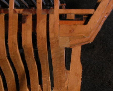
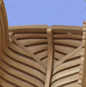
HMS Psyche drawings

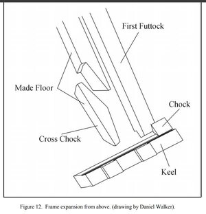
As you said, I have reviewed the other ships and noted that square frames were used.
All the ships built at Kingston wee unique and quite possibly one of a kind.
I haven't gotten to the decks yet and already I suspect there was something different there.

I watched a video on installing a square frame on a wood vessel and it has a ledge that the back of the frame sits on but the front edge buts to the deadwood. It still gives the impression it is just bolted to the deadwood. Unique.

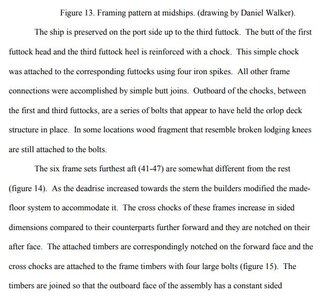
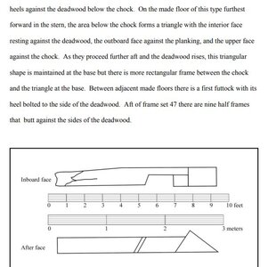
On the Princess Charlotte, walker contends by archeological data that doubling up frames was used. This was something I lookedat the startof the framing, but can't see that now.
The St.Lawrence was different because of it's size but still used square frames.
The only thing I am thinking of now is the ship was designed and manufactured in England, and cants were used but bell/Strickland used methods in Canada that were tried and tested some what already.
The plans showed cant frame ideas at the transoms, and remained because they could not "erase" what was there. Just draw over or use ///'s through something drawn that they didn't use. I saw this used repeatedly through out the drawings.

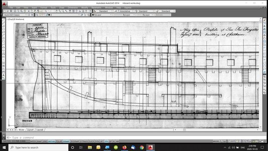
As far as the inboard works drawings there was only what I just showed above. The profile withe the body plans shows something different. Nothing.
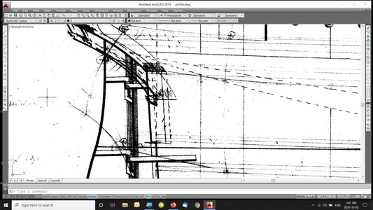
transoms b.jpg
 
after reviewing the data it is clear the English did not use cant frames in the stern of the Princess Charlotte and most likely did not use them in the Psyche.

This is the pit fall of looking at any set of Admiralty plans and assuming that is how any one ship might of been built. Without archaeological data you are guessing as to the actual construction.
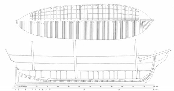
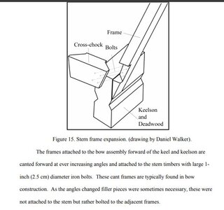
looking at the drawing based on the wreck it is clear the stern frames are square to the deadwood, no doubt about it. to the right cant frames were used at the bow.

pcf9.JPG
 
i found the inside profile on an old computer that was decommissioned so let me bring it into CAD and see what's up with those stern frames.
 
So I have been seemingly trying to decide about the use of a cant frame in the stern.
It was discussed that the British had the frames already from England so why not use them. This would include any and all cant framess.
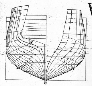
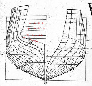
But I relooked at the body plan and noticed again that Bell/Strickland had crossed out the cant frame and then modified the 3 frames to allow for the wideth. Frames 22,23 and the one at the wing trsndom were made wider.
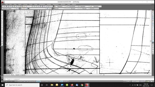
I haven't done a great job at it but you can see drawn lines around the last frame at the deadwood and see how Shipwrights draw cant frame symbols. Further up the frame you will see more circles and I am trying to show lines that were used to show discarded information. In this case the cant frame. Also he also discarded the counters and placed new ones.
If you look at frames 22 and 23 he made them wider as well.
My onlyconcern now is the frame attached to the wing Transom. Where does it go and how. Does it bolt to the top of the Transom , side, How does the planking go?
All questions I have to answer before I can continue with the framing plan.
cant frame.jpg
 
taking a look at the body plan it look to me like the wing transom was moved up and body lines 22 and 23 were adjusted

psyche3.jpg

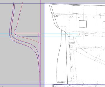
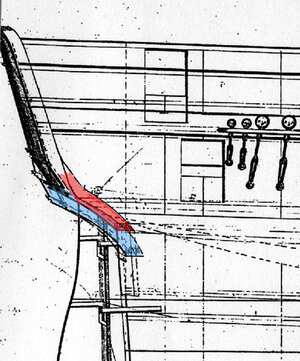
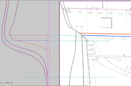
looking at the tracing the blue lines are the originals the red lines are the adjusted lines. Looks like 22 and 23 were also raised up a little and a 24 added. The light blue lines are the locations of the transom the lower one being the original and upper one the new location.

transom2.JPG

the outside profile confirms the transom was raised

stern timber.JPG
 
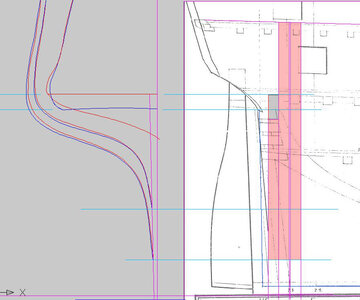
as far as the fashion timber and frames go they could either have been canted or set square. There is a blue line running along the bottom and up the stern post which is the rabbit everything inside that line is deadwood. The fashion timber (short frame) has enough room to sit against the deadwood then the next 2 frames. The gray area above the fashion timber is the new location of the wing transom.

frame23a.jpg
 
My only concern now is the frame attached to the wing Transom. Where does it go and how. Does it bolt to the top of the Transom , side, How does the planking go?
All questions I have to answer before I can continue with the framing plan.


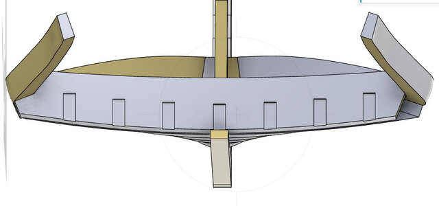
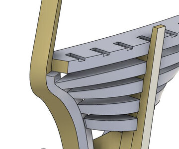
to the left the end of the wing transom notches around the last frame on the right i cut away the end of the transom so you can see the top of the fashion timber.


wt1.JPG

here you can see a cut away of the end of the transom sitting on the top of the fashion timber. at the center the transon sits on top the deadwood or inner stern post


wt2a.jpg
 
WOW There is certainly a lot to be said about 3d. I retired way to early.

Can I present a contrary argument here.

If the decks were lowered 21" as per modified plan, and you raise the transom, you effectively have to raise the deck. Steering would be an issue among other things.
According to the N.M.M.
"Scale 1:48. A plan showing the body plan, sheer lines with midship framing, longitudinal half breadth proposed (and approved) for building Psyche (1814), Prompte (1814), both 32-gun, Fifth Rate Frigates. Note the modifications dated December 1813 to lower the decks and corresponding gun ports. On March 1814, this plan was sent to Canada for building the Psyche (1814) on the Lakes, after additional modifications to add a spur deck. Annotation: top right (black) ; "The deck to be lowered, in other respects this Draft is approved for the frames of two ships for service or the Lakes in Canada. To be prepared with all possible dispatch to be constructed of fir timbers: 22 December 1813." top (red) ; "A copy sent to Chatham 23rd Dec 1813 agreeable to the alterations in red with the Head, Cathead Bowspirit & Dead Eye And Wale lowered 1ft 9in" top left (black) ; "By order from Sir Robert Hall Acting Commissioner of the Navy to Canada, dated 9th Nov 1814. The Pysche was to have a spur deck added to her capable of carrying guns fore & aft."

I have to re adjust my thinking because your argument makes sense. But I still have my doubts. As the lines you are showing me are crossed off, like I showed and of course its a modern way of erasing something you can't erase. Which would mean what you propose is opposite.

You said before that working from admiralty drawing has it's pitfalls, but I be leave you can sort through the data it is showing you and come up with as close to reasonable as you can get. I agree you need archeological data for better results.
Again these ships were very unique and now I be leave one of a kind.
 
Ok I have done some thinking( dangerous I know) and I still can't be leave they raised the Transoms.
Look at the Profile plan , in the upper center and you have the stats of the ship. Importantly they lowered the Depth of Hold from 12' to 10'3".
If they lowered it 1'9" that means the transom at the stern post would be lowered as well. Now if they have not changed the sizes of the Transoms and the spaces between, then that means they Lowered the wing Transom.
Also I be leave you are mixing up the so called 24rth frame as what was drawn after the original drawing was made. I be leave it is a cant frame and was crossed off by Bell/Strickland for the other square frame timber.
As I showed before, there are cross markings that I beleave represent lines that were not used. IE: the 24th frame. There is plenty of evidence on the profile plan of it's use. Examples: Look at the keel on the body plan. The lower parts are cross hatched off for something else.
Again on the profile plan midships, the wales (old) are cross hatched off and the new wale location is a deeper , thicker black line.
I know it's not exactly science but this thicker wider black line is used almost on every plan to show changes. Deck plans have them as well.
So back to the body plan.
The frames in question, 22 and 23 the thicker darker wider black lines are lower than the other ones. I beleave because the Transoms are lowered these are the needed shapes. Frame 24, the line that ends at the Transom is wider, thicker and darker than the line above.
Lokk at the body plan on the upper right side. The 2 cant frames T and W he has drawn in darker thicker lines that are drawn past the rail curve.
Drawings done as built etc. at the N.M.M. I have noticed are precise and drawn neatly no ink spills or over drawn lines.
I know it's not much of an argument but if you take everything together it does make sense.
 
i am still trying to figure it out
i thought maybe i have it reversed and the red line is the original and the blue line the dropped location of the transom. The blue line lines up with the side view of the transom so the question is where those transoms original or drawn in later "after" the transom was lowered?

looking at the profile the red line is the original deck line and the blue line is the deck when i was dropped.
What made me think the transom was raised is because the red line location of the transom lines up perfectly with the lowered blue deck line.

could very well be the transom was not moved at all. If it were moved i would think the revised location would be drawn on the profile

this is quite the puzzle to figure out

deck.JPG
 
are you saying the marks in the red circles are Xed out lines? that could be, i took them as measurement ticks to draw the lines. The are spaced to even and if they were to X out the line they are really not an X

i need to go back to the profile and see if these lines are carried over to the profile

bp2.jpg
 
I am saying that they represent x ed out lines. There are to many on the plans. Look at the bottom of the keel the same thing.
If you magnify your screen like I do to see, frames 22 and 23 also have them on there.

Yes it is quite the puzzle and challenge. But I find that I am thinking of this even if I wake up in middle of night.
Very stimulating for an old man.
 
i am still trying to figure it out
i thought maybe i have it reversed and the red line is the original and the blue line the dropped location of the transom. The blue line lines up with the side view of the transom so the question is where those transoms original or drawn in later "after" the transom was lowered?

looking at the profile the red line is the original deck line and the blue line is the deck when i was dropped.
What made me think the transom was raised is because the red line location of the transom lines up perfectly with the lowered blue deck line.

could very well be the transom was not moved at all. If it were moved i would think the revised location would be drawn on the profile

this is quite the puzzle to figure out

View attachment 183944
Ok a couple of important things, I think.
The drawing you are using is the inboard plan after the changes were made. The decks and Transoms lowered but for some reason cant frame against Transoms still evident.
However, Now I am going to through the BIGGEST monkey wreck into the mix. Your red line is the top of the deck but the blue is not a deck. Let me explain my reasoning here.
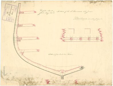
The St. Lawrence and the Princess Charlotte we know did NOT use hanging knees or possibly not even Lodging knees. Only in the Orlop deck. Anyway. What you are possibly seeing are 5" x 5' carlings like the St. Lawrence x section. The beam you are seeing is the lower part of a much bigger beam. 11" x 15" The 3 carlings are notched into the beams and bolted through the beam to the shelf and also through the frames. Also fefer to Kopp article. She explains it better.
The wrecks of St. Lawrence Regent, Charlotte did not show any evidence of knees.
Also I think the carlings are bigger on the 2 upper decks.
So looking at your drawing eliminate the blue line, and the drawing is good. Clearence between Wing Transom and the deck bracing for a tiller to pass through.
As I said I am thinking of this all the time and enjoying it. Having you and others discuss it is great. A way to unravel the past a bit.
lawrence x section.jpg
 
My only concern now is the frame attached to the wing Transom. Where does it go and how. Does it bolt to the top of the Transom , side, How does the planking go?
All questions I have to answer before I can continue with the framing plan.


to the left the end of the wing transom notches around the last frame on the right i cut away the end of the transom so you can see the top of the fashion timber.


View attachment 183804

here you can see a cut away of the end of the transom sitting on the top of the fashion timber. at the center the transon sits on top the deadwood or inner stern post


View attachment 183817
If I understand this correctly, the frame would butt against the transom, as a normal half frame and the fashion piece is butted , bolted to it.
Let me try this again. frame 222 half frame to deadwood. Frame 23 half frame to deadwood normal 4" space between.
Now frame 24 half frame and a normal 4" space between them, notched into the Transom. the fashion piece is butted next to frame 24. Correct? Then the transoms all are notched into it.

Is this something used in other ships.
I like it, just trying to understand it.
 
Besides the wing Transom area, I have continued with the Inboard works plan. The more I finish, I am questioning my idea that the gun ports for the 32 pounders are to proper size. Reasoning here is, if they built the frames in England and then shipped them, the gun ports would all be the same 36" across and approx. 36" high. That being the case the top rail would be lowered and the ports more closer to the upper decks.
I guess my problem is it would be tight to ram a 32 pounder into that port and fire it. I am probably thinking to much about what should be and what is. Strickland had to build it as per Yeo's specifications at the time and without cutting to much out of the existing frames or not at all.
The inboard plan drawn is supposedly as built with all modifications included.
I am nearing a place where I must make a decision and then I can continue with the decks, Masts.
 
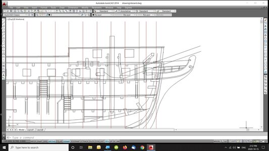
So im the next picture I added the figurehead, head, rails, cathead and Bowsprit. These were lowered the 1'9" dimension as described by the Admiralty.
Now if you notice my idea of the gun ports for the 32 pdr are wrong. As the top rail is to high. It also will have to be lowered the 1'9' dimension.
This brings me back to my earlier question about assuming what should be and what is. Strickland did not change the upper gun ports for the 32 pounder but instead left them as they were shipped from England, or 36" wide between frames. The height would be to the top rail.
I apologize to people because I ask myself a lot of questions and then look for the answers. This is how I work.
On a ship from a British yard, would probably use establishments to build her. But in Lower Canada, in 1812 and earlier, Ships were built using methods used by the yards there. The shipwrights employed were a mixture of French, English and possibly other nationalities and their methods were different than the British way. So as I have said before the ships built in Kingston were very unique and possibly one of a kind.
As dave Stevens has pointed out, you can not produce an accurate historically correct ship from the Admiralty plans, but you can produce a reasonably close copy from ships previously built at the same yard. And at Kingston, only 4 ships of the line, were built, so you can reasonably use evidence from their wreckage's to build the others.figurehead.jpg
 
If I understand this correctly, the frame would butt against the transom, as a normal half frame and the fashion piece is butted , bolted to it.
Let me try this again. frame 222 half frame to deadwood. Frame 23 half frame to deadwood normal 4" space between.
Now frame 24 half frame and a normal 4" space between them, notched into the Transom. the fashion piece is butted next to frame 24. Correct? Then the transoms all are notched into it.

Is this something used in other ships.
I like it, just trying to understand it.


There are a number of ways to build a stern and each naval yard had their own ideas. Around the time of the war of 1812 square stern were starting to be replaced with round sterns. We know William Bell had a hand in the building of the ships at Kingston, we also know Bell ran the British yard at Amherstburg and the town of Amherstburg was a French town so most all the workers in the shipyard were French carpenters. We also know the ships at Kingston were contracted out to shipwrights from Quebec. When the Americans over ran the fort Bell and his crew went to Kingston. So we can sort of suspect a heavy French influence in the way ship were built.

as5.jpg

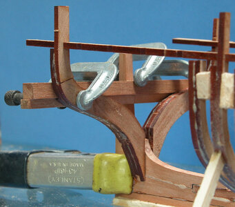
the main timber in the stern was the wing transom and you can think of it as the foundation for the stern timbers. This was a massive heavy timber and it had to be supported,

as3.jpg

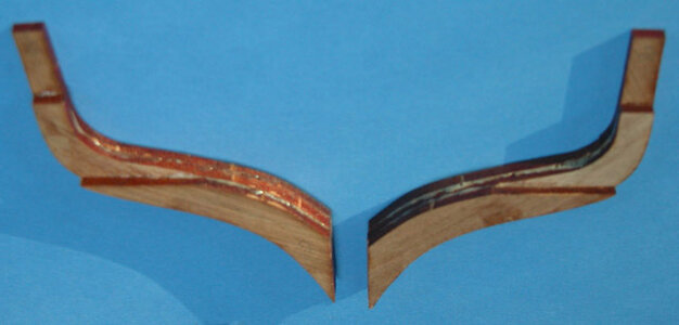
in this lake schooner the heavy transom sat on the triple fashion timber, the lower ledge is where the transom sat.

as2.jpg

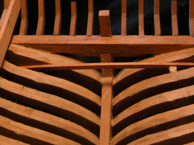
a view from the inside shows the stern timbers were square to the keel

as4.jpg

in this stern the transom sat on the fashion timber which is square to the keel

as1.jpg

a side view shows the end of the transom with the stern timbers set into the back face

tran2f.jpg

in this case on a French stern the frames are square to the keel but the fashion timber cants back so the transom can be bolted to the back side. The the hull frames are built off the fashion timber. Sometimes the wing transom sat on the fashion timber sometimes it is bolted to the back face of the fashion timber.

The actual way the Psyche stern was built is an unknown. All you can do is figure in the circumstances at the time, who built the ship and take your best guess.
 
Last edited:
Back
Top