HMS Psyche drawings

Well not to get to excited but I seem to have answered ny own question about the triple.
If you start at the station x a frame against the port and then working towards the stem, 5" then another frame,when you measure from the frame against the other port it measures 39". 3 frames together leaves 1.5" ether side.
Now this is to start, I just don't want to get to excited.
Not to put a monkey wretch into this but can it be proved that this spacer was added in Kingston?
I know what you will say, they have to use the original frames and they are designed for a specific spot on the keel, given the high rise. But would production be slowed because of the added bolting to be done.
 
i think i would frame the hull as it was intended with 12 inch sided frames with a 5 inch space. That is the olny thing that is for sure, what Bell and Strickland did is an unknown at best it is just a guess.
Why build the Psyche rather than the Princess Charlotte that does have avaliable information?

if the frames were single how were the futtocks attached to one another? I am thinking maybe chocks but that would be quite a puzzle as each chock was cut and shaped to it's location in the framing so if you had a pile of chocks it would be a major problem to find the right chock to fit the right frame joint. My thought was maybe a lap scraf was used to join the ends of the futtocks that way there is no need to find the correct chock to fit a connection.

the use of chocks was a weak connection and relied more on the planking to hold the frames together.
 
i think i would frame the hull as it was intended with 12 inch sided frames with a 5 inch space. Why build the Psyche rather than the Princess Charlotte that does have avaliable information?

I could but you have already undertaken to draft and possible model kit for it.
I would like to draft the Psyche build it because it is unique. The last warship built on the lakes for the war of 1812.

i think i would frame the hull as it was intended with 12 inch sided frames with a 5 inch space.

I have had time over night to really think about how it was framed. It would be foolish to recut any frames, when you are supposed to have then already available.So that said, you have to build it as intended, with the methods they used for construction. IE: a rising wood or hog on top of the keel to accept the notches for the floor timbers, and cross chocks used.
If you look closely at the very first frame at the keel you would see lines representing the hog, frame floor height and the limber strake thickness.
Not to argue but again look at the frames at the (A) station. you have frame, space (measured on those plans as 5") another frame another 5" space, another frame but this time the space is measured 2", The next set of spaces are all 4" measured. So you would say well that could be a difference in how I enlarge the drawing to the right 130' established measurement.
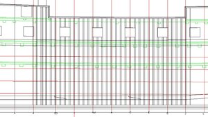
True, but now lets look at the size of the ports. They are approximately all 36" wide. The established distance centered between ports is 112', So if you subtract all the frames at 12" sided and then take that total and divide by the number of spaces you get 4" spacing through out.
This I have done and drawn out and works well. Some ports are slighly off(.5") but nothing huge.

The cross chucks would be all the same along the keel area. Just like other construction done.At the stem would be cant frames so that doesn't change. The only area I can see questionable is the stern area.


the use of chocks was a weak connection and relied more on the planking to hold the frames together.

Yes I agree but if you read Walkers article he stated that some of the chocks used between floor and futtocks were not bolted but rather the planking held then together.
 
Ok so I was curious to know the gun port spacing. The original Psyche was to be a 36 gun 5th rate frigate. She was expanded to 54 guns. The ports were only 36" wide, and if you go with Goodman's calculations on gun ports, this ship was probably designed for an 18 pounder.
So they increased the guns to 24/28 pounders on the gun deck. I have a / between the 2 gun sizes as there are conflicting reports as to what was on the gun deck. Anyway, again looking at Goodwins calculations, a 24 pounder the width should be 40". But based on the fact that the frames were pre built, the 36" width would not be cut wider. The 4" spacing would continue right across to the wing transom.
Now for the upper ports. Here I may have gone a little overboard. The original only had 4 ports per side on the Quarter deck. Commander Yeo ask for heavier guns on the quarter deck and forecastle. They also built a spur deck between the two to make both decks accessible and carry extra guns.
Yeo wanted the 32 pounder Cannonades. These guns do not need the room to operate like a regular cannon. The front base is bolted to the deck next to the waterway and the approximately 6' of carriage only swivels like an arc.The recoil is limited to the carriage frame.
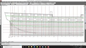
So according to Goodwin's calculations again the width should be 41"\but again the frames are preset so maybe no adjustments here as well. But the working room between the cannonades is important. Approximately 80". There are 2 ports in front of the rear mast. they are approximately 75" apart. Again this is because they were intended for smaller cannons. I used this dimension and created the other ports. As you can see in the picture the ports are in place. The next measurements would be if 4 more cannonades can be placed on the spur deck.
I deviated from what was drawn to enable the ship to carry the 32 pounders as ordered. PLEASE correct me if I crossed a line.
"'framingb.jpg
 
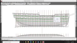
I have pretty much finished the framing. The stern I have included the bearding line and frames all the way to the end. In the front I have completed the cant frames.
Included in the framing plan is the half breadth framing. It gives you an idea how the frames are laid out. Helps to pick up any errors.
The other job was to include the heads of the frames at the floors and futtocks. Useful for locations of the framing chocks.
framing half.jpg
 
Ok I said I was pretty much finished the framing plan.
I added the second Wale that was located over the decks of the quarter deck and spur and forecastle. It is 21" wide like the other one. I could speculate what it's purpose is but not right now. To say I have a lot of ideas around this is small.
From here I reexamined the upper gun placements and sizes.

For a 32 PDR. carronade the port must be approx. 150" between centers 21" above the deck 40" wide with a height of 36.6". Davis's book Model ship Assistant gives the sizes based on the dia. of the ball. For a 32 PDR ball the dia. is 6.1" Each measurement is a mathematical equation.
So based on all of this, I re positioned the ports as per measurements. There is one less port from what I originally drew. This looks more approprate.
Once this was done I had to reposition the top rail.
I will be moving on to the body plan, profile and half breadth plans. They are all interconnected.
fframe.jpg
 
you mentioned the use of 28 pound cannons and someone said there was no such thing. In researching the Paixham shell guns i came across an article saying the British were experimenting with re-boring cannons so it is very possible a 24 pound cannon was indeed re-bored to 28.
From 1800 to the 1860 cannons were being reinvented thus the Paixham, Parrott and the Dahlgren guns were being designed and refined.
This goes to show you can not always count on the obvious stated research you have to look at the big picture and see what in totality is going on.
In your travels around the Great Lakes you mentioned that a 28 was evident and you showed a picture of that gun. ( if a read that description right) Anyway assuming they "rebored" to a 28, I assume the outside dimensions of the cannon would be the same. So changing port size then would not have to be made. Interesting.
Would the truck have to be increased to handle the larger recoil?
 
i can not say if "in fact' the Psyche had 24s re borded to 28 or there was an actual 28 design. i did come across cannons like i said that did not fit the standard dimensions to big for a 24 and to small for a 32 but not being an expert in the field of naval guns i could not ID the gun i just noted it as an "odd" size
if the Psyche carried re bored 24s the size of the gun would be the same so would the carriages same size gun just a bigger bore. Good question about the recoil i would think a 28 would pack a bigger punch and longer range and a bit more recoil.

question where did the guns come from? were they part of the kit and sent from England, did Strickland get guns from another local source, did they get them from the Americans?

at this point all we know for sure is the practice of re-bording guns to a larger size did happen.
 
so Dave i will dig a little deeper into the gun question but at a modeling scale the difference between a 24 and 28 is so slight you may want to consider using a 24
 
It is kind of you to research the gun.
That is why I asked about the size of the gun if they rebored it. The 24 size would be used therefore the gun port would stay the same.
 
There may very well been 28 pound guns on the Psyche. The British were experimenting with boring-up cannons and the 28s could have been a experiment, 24s were first bored-up to a 32 but that was a little to extreme so maybe boring-up was backed down to 28. The Psyche itself was an experiment in the "fir built frigates"
by about 1830ish bored guns were no longer used and just bigger guns were designed. By the 1830s the war ship Mississippi had 2 monster 120 pound guns on the bow.

bg1.JPG

bg2.JPG

bg3.JPG

bg4.JPG

bg5.JPG

bg6.JPG
 
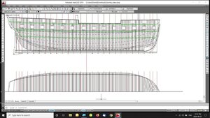
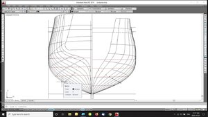
Finished up the Body plan. As the drawings I am doing are full scale, a slight defect of .078 was noted on one frame. I decided not to correct it.body.jpg
 
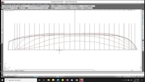
I transferred the waterlines to the half breadth plan. Here any defect with show up. And sometimes very noticeably. As it turned out the frames were faired very evenly. That done Itransferred the waterlines to the framing half breadth so when I have to construct the cant frames I have guidelines.half.jpg
 
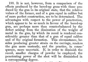
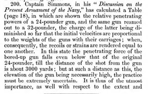
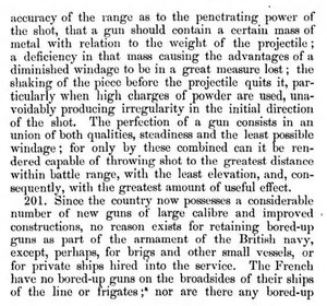
It seems to rebore is not as helpful.
From the first part, mentions the rewcoil is greater than that of the same calibre. So using less powder is the solution. Also a greater strain on the carriage as I probably thought.
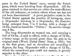
Interesting that he comments on the American rearmed long 42 as superior with a less charge of 12 pounds than the original 14 pounds.
Even though the British Navy used the rebores, from the article I believe the practice may have been stopped, as breechings occurred even after reduced powder was used.
Interesting articles. Thanks.
 
I am having a problem accepting the framing at the transoms.
if you look at the Body plan above you will see on the left side the frame 23. The frame above it is the wing transom with the counters showing the curved look.
Ok. This frame (23) butts up to the deadwood in the stern. It does NOT show that it is a cant frame. So I drew the frames square to the deadwood. The transoms are shown above as straight no curve.
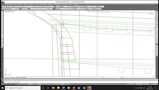
OK here's my problem. In the profile drawings by Strickland, it shows the transoms as though frame 23 is a cant they are angled not square.
If I look at canting frame 23 it does not work. The gap between frames is in the order of 14". To large.
So I will keep thinking about this for a while.transoms.jpg
 
OK here's my problem. In the profile drawings by Strickland, it shows the transoms as though frame 23 is a cant they are angled not square.

if 23 three is shown as a cant then perhaps it does cant. Review the archaeological study of the other wrecks and see how the stern frames are placed.

this is an English designed and built "kit" and the British used cant frame for and aft.


If I look at canting frame 23 it does not work. The gap between frames is in the order of 14". To large.

if you start canting the frames starting at the forward end of the deadwood you can even out the spacing between all the cant frames.

So I will keep thinking about this for a while.

thinking about it i would use the drawing as my prime source of information then look around for supporting information pro or con. so if the plan suggests the stern frames are canted but all the other ship were not i suspect the plans were not followed exactly. But if the plans suggest the frames were canted and the archeological evidence shows all the other ships built by the same shipwrights were canted it is likely so was the Psyche.
 
quickly going through the research it does indeed suggest the stern frames on the ships built at Kingston did NOT use cant frames at the stern. They were set square to the deadwood.

this is why researching is sketchy especially with secondary sources like books written in modern times. These sources suggest the English built hulls with cant frames at the stern, but yet here we have ships built in English yards both in Canada and England with square frames at the stern.

i do not have the inside profile plan to look at so i can not comment on how it is drawn.
 
Back
Top