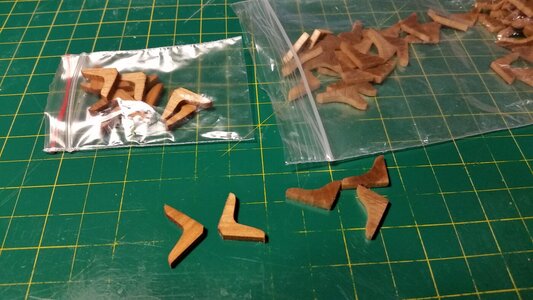
The bitts came out really nice.
-

Win a Free Custom Engraved Brass Coin!!!
As a way to introduce our brass coins to the community, we will raffle off a free coin during the month of August. Follow link ABOVE for instructions for entering.
-

PRE-ORDER SHIPS IN SCALE TODAY!
The beloved Ships in Scale Magazine is back and charting a new course for 2026!
Discover new skills, new techniques, and new inspirations in every issue.
NOTE THAT OUR FIRST ISSUE WILL BE JAN/FEB 2026
You are using an out of date browser. It may not display this or other websites correctly.
You should upgrade or use an alternative browser.
You should upgrade or use an alternative browser.
HMS Sovereign of the Seas - Bashing DeAgostini Beyond Believable Boundaries
- Thread starter DARIVS ARCHITECTVS
- Start date
- Watchers 105
I agree with Paul (PGN). Those are simple pieces but very well executed.
Kurt,
Buried your in-box with likes! really great work. I like how you scraped the decks, your adding lots of excellent details - Glad that I caught up,
Cheers,
Buried your in-box with likes! really great work. I like how you scraped the decks, your adding lots of excellent details - Glad that I caught up,
Cheers,
Thanks everyone! The Sovereign will be packed with as many small add-ons as can be made. All the added features are made with basic techniques, but the quantity of these adds up and makes the model look complex and realistic. Paul added zillions of dots to create the bolts and trenails on his Wasa, and the final result is fantastic. As a form of training, the Sovereign will have all visible decks filled with details as much as possible. It will a very long time, but it will look like a real ship if you view the insides really close. What I wish I could do is make convincing human figures for the decks. I would be willing to buy lots of painted figures from somebody if I find enough 20mm sailors.
Nice deck planking seams following the scraping. Sharp razors remove the whiskers so when I ordered more I got 100 so that I can change them often. Your work is progressing well. Rich (PT-2)I found that darkening all sides of the thin plank strips with black Sharpie marker causes the ink to bleed into the ends of the plank, and the lines to be too dark and coarse. That was noticeable on my last ship. To reduce that effect, four things were changed. The marker used was switched from black to brown, only one long edge was darkened, the ends were not darkened, and the deck was scraped smooth with a razor scraper. This deck may not be as smooth as decks to follow, because of access limitations, but it's smoother than leaving it unscraped like on my last model. The port side looks a little lighter in color, but I hope it will age and darken to match the rest of the deck.
The deck planking for the lower gun deck is finished, except for the waterway strip on the port side, which I need to get more 1.5 x 1.5 mm strip to complete. Did ships this early have a spirketting plank above the waterway?
The deck was coated with Krylon Satin spray lacquer. It adds a small amount of shine without making the wood look like it was dipped in glass, which looks terrible in my opinion.
CRAP. I forgot to do the midplank trenails again.
I'll get them later.
View attachment 250853
View attachment 250854
View attachment 250855
View attachment 250856
View attachment 250857
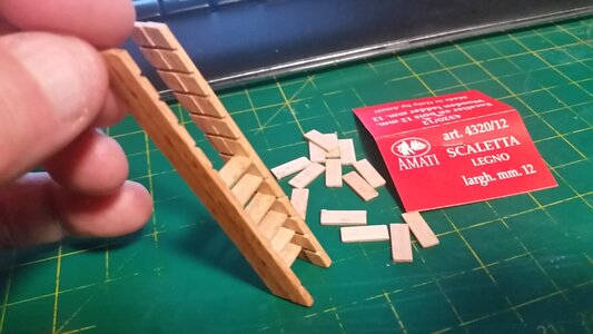
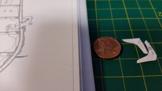
More planning for scratch-made parts. Using Amati ladder parts, experimentation was done making "S" shaped ladders. Two strings (rails) are needed to allow the treads to form a shallow "S" curve, and these would be trimmed by sanding to follow the edges of the treads. Treads (steps) would be added between the treads that the Amati ladders already have slots for, doubling the amount of steps for these 12mm wide ladders. Also, paper patterns for upper and lower deck knees were made for the lower gun deck. I have some strips of 3mm basswood that will be cut into knees and stained. Before any of these parts are made and installed, the cannons must be installed or there will be no room to work.


Here are the rough sawn upper and lower knees for the lower gun deck. They need to be sanded and stained. The upper knees were cut individually from a flat stick of basswood since there are only twelve of them. A stick of pine was routered out in the shape of the upper knee, then slices were made using the Delta 890 bandsaw, which has proven to be very precise at cutting small parts. Once sanded, the fuzzy edges will be very sharp.
PS: If anyone has a cheap spare laser cutter they to give away, I'll take it! It'll save me lots of this sort of repetition...
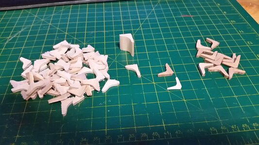
PS: If anyone has a cheap spare laser cutter they to give away, I'll take it!

- Joined
- Aug 30, 2020
- Messages
- 676
- Points
- 353

These enhancements take SO MUCH TIME - but they will add up and will result in a fine model of this ship (though I suspect these will be hard to see unless you intend to leave some decking off (?).Knees sanded and stained. The lower knees made of basswood look better than the upper pinewood ones.
View attachment 256096
Know what REALLY took time? You making all those freaking little dots on your Wasa!These enhancements take SO MUCH TIME - but they will add up and will result in a fine model of this ship (though I suspect these will be hard to see unless you intend to leave some decking off (?).
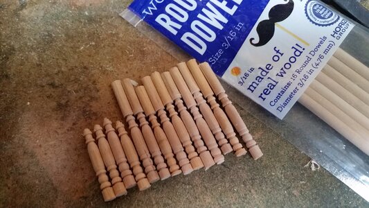
I ordered some etched 1.5mm eyebolts from Radimir at HiS (Historic Ships) in Czech Rebublic and are waiting for them so the cannons breach ropes can be made. So, in the meantime, columns or pillars were fabricated for the lower gun deck. Since shipping Caldercraft column parts from UK is so expensive, they were made from scratch. I took a trick from Shelk, who made the finest weathered Santisima Trinidad I have ever seen, and created a cutter from a razor blade in mere minutes using the cutting wheel on the Dremel tool. To keep the spinning piece firm while shaping, sections of 3/16" hardwood dowel were cut on the bandsaw and placed in the chuck of the tabletop drill press. The drill press was set to maximum speed. The razor blade cutter was clamped in a machine vise and pressed carefully into the side of the spinning dowel. Sometimes, as the part diameter approached 3mm at the top end, the piece simply broke off. But, the part is still usable. Each pillar was also spun in a hand drill while pinching a green Scotchbrite scrubbing pad around the spinning part, polishing the wood. Then they were all stained with dark walnut Danish Oil.
The whole process took only a couple hours, faster than I thought. Also, the pillars cost mere pennies. Later, each pillar will be cut to length and installed as the beams above the lower gun deck are fitted.
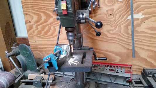
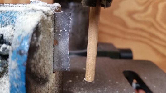
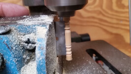
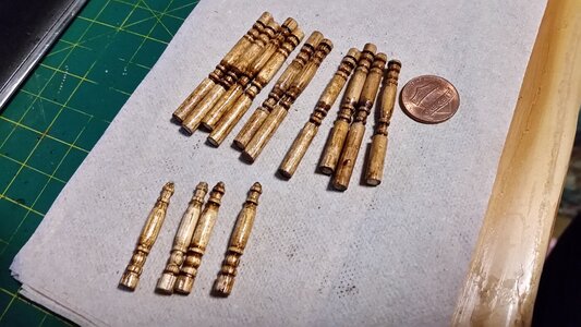
The whole process took only a couple hours, faster than I thought. Also, the pillars cost mere pennies. Later, each pillar will be cut to length and installed as the beams above the lower gun deck are fitted.


Very, very well done all due to your shaping of the razor to the cutting profile. That is a skill within itself!!! Rich (PT-2)I ordered some etched 1.5mm eyebolts from Radimir at HiS (Historic Ships) in Czech Rebublic and are waiting for them so the cannons breach ropes can be made. So, in the meantime, columns or pillars were fabricated for the lower gun deck. Since shipping Caldercraft column parts from UK is so expensive, they were made from scratch. I took a trick from Shelk, who made the finest weathered Santisima Trinidad I have ever seen, and created a cutter from a razor blade in mere minutes using the cutting wheel on the Dremel tool. To keep the spinning piece firm while shaping, sections of 3/16" hardwood dowel were cut on the bandsaw and placed in the chuck of the tabletop drill press. The drill press was set to maximum speed. The razor blade cutter was clamped in a machine vise and pressed carefully into the side of the spinning dowel. Sometimes, as the part diameter approached 3mm at the top end, the piece simply broke off. But, the part is still usable. Each pillar was also spun in a hand drill while pinching a green Scotchbrite scrubbing pad around the spinning part, polishing the wood. Then they were all stained with dark walnut Danish Oil.
The whole process took only a couple hours, faster than I thought. Also, the pillars cost mere pennies. Later, each pillar will be cut to length and installed as the beams above the lower gun deck are fitted.
View attachment 256254
View attachment 256255
View attachment 256256
View attachment 256257
View attachment 256258
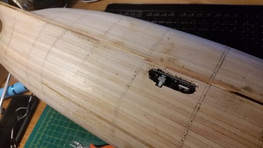
This should have been done much earlier in the build, but it's not too late. The electronic board that feeds three 3V LED circuits has to be installed. Since all the lower hold and orlop deck was sealed off, it was time for surgery! A large hole for accepting and mounting the board was crudely drilled into the bottom of the ship. It has a plug for plugging in the transformer, which coverts 60 hz AC to 3V DC. Three circuits made up of 6 wires were fed up through a hole in the lower gun deck where the capstan will be. With some careful scratch building. the capstan shaft will be made hollow, possibly using thin metal tubing painted to look like wood, and one set of wires will pass up through it and emerge just below the deck above, joining wiring that will be embedded in the beams above for overhead lanterns. The remaining four wires will continue up to the middle gun deck, where two will power overhead lanterns, and two others will pass aft and forward to power lights in the stern and fore castles. Each circuit will have six 3V LED's powered by it. a resistor still need to be placed in each of the circuits. The electronic board will be epoxied into the hull just below flush with the hull planking, and covered with the second layer of planking, leaving a hole for the plug open.
The plan is to solder one resistor to each positive wire, the solder each of the six wires to very thin, long wires. The black connectors you see, plus their resistors, will be stuffed back down the capstan hole down into orlop deck below. This leaves the sic very thin wired to be routed up and branching to all the LED's on all decks.
When you forget to build a feature into the model, and it gets covered up like this circuit did, you have to get very clever to get it installed without destroying the work you've done so far. I've always been good at Jerry rigging my way out of trouble. (Must be the German in me, or actually Austrian!) Either way, I can fix this.
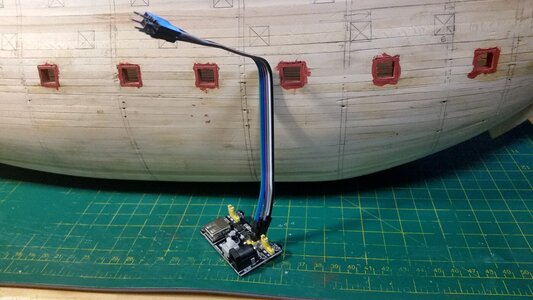
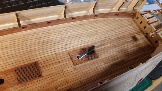
The board will be epoxied in this position. The white On/Off switch will have a metal tab attached to it that will protrude through the bottom of the hull, even though it may never be used because power to the transformer will be controlled independently.
The plan is to solder one resistor to each positive wire, the solder each of the six wires to very thin, long wires. The black connectors you see, plus their resistors, will be stuffed back down the capstan hole down into orlop deck below. This leaves the sic very thin wired to be routed up and branching to all the LED's on all decks.
When you forget to build a feature into the model, and it gets covered up like this circuit did, you have to get very clever to get it installed without destroying the work you've done so far. I've always been good at Jerry rigging my way out of trouble. (Must be the German in me, or actually Austrian!) Either way, I can fix this.


The board will be epoxied in this position. The white On/Off switch will have a metal tab attached to it that will protrude through the bottom of the hull, even though it may never be used because power to the transformer will be controlled independently.

Man the pumps!
an interesting way to turn the wood. Given that I know you have a lathe, may I ask why the drill press was chosen as apposite to a lathe? Is there any specific reason?To keep the spinning piece firm while shaping, sections of 3/16" hardwood dowel were cut on the bandsaw and placed in the chuck of the tabletop drill press. The drill press was set to maximum speed. The razor blade cutter was clamped in a machine vise and pressed carefully into the side of the spinning dowel. Sometimes, as the part diameter approached 3mm at the top end, the piece simply broke off. But, the part is still usable.
Hmm....more control? The cutter should go slightly above the centerline of the wood. If the 'tool' is not firm against the wood piece, you risk getting hurt, IMHO. Horizontally you have more control, don't you think?@Jimsky I think, because I would do the same, more control. You can drag the clamp over the table of the drill stand
Before Kurt will elaborate... Here are the few basicsYes you have to be in control and be careful. Looking out what Kurt would say.
- The Tool Should Always Contact the Tool Rest
Additionally, there should be a limited distance between the point where the tool comes into contact with the tool rest and where it contacts the wood. The greater the distance between the two points of contact, the less support that is provided to the tool.
- Hand Positioning
- Use the Bevel
- Cutters Lead and Scrapers Trail


