HMS Sovereign of the Seas - Bashing DeAgostini Beyond Believable Boundaries

an interesting way to turn the wood. Given that I know you have a lathe, may I ask why the drill press was chosen as apposite to a lathe? Is there any specific reason?
It spins faster, and it was faster to set up in the drill press. I held the cutter with by the vise with my hands and could feel how the angle of the cutter and the applied pressure. The position of the cutter was precise using the drill press and vise. The weight of the cutter/vise and the easily broken dowel ensured that the cutter could not be grabbed by the wood and flung around the shop or into my body. Like Jimsky said, good judgement with regard to the forces involved and control of the cutter are important for safety. WOOD GRABS CUTTERS if the pressure is too high and/or the angle is leading too much. This why wood lathes have a solid rest close to the work, and the hand held cutters are long to provide leverage and control. In my example using the drill press, the table provided stable platform, allowing me to position the angle and cutting pressure with great precision. The small size of the dowel (small diameter) also was a factor. Four of the parts snapped off when too much pressure was applied. The parts created no force on the cutter when caught on the cutting edge. Doing large parts with a hand held cutter, like holding a small metal vise, would be unsafe because of lack of leverage required to maintain control. As a machinist, you have to judge carefully when to use techniques like this from a safety standpoint.
 
Last edited:
You gotta know your tools, guys...

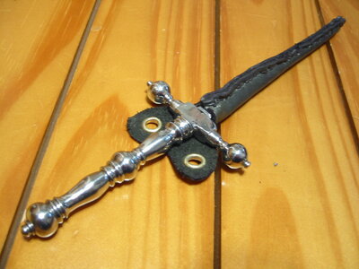
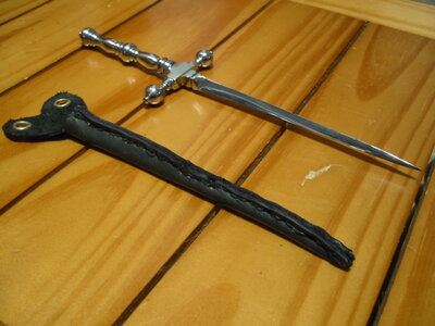
I made THIS on the very same drill press from a fan motor shaft, using the same method almost two decades ago. It's an Italian bodice stiletto. While the steel rod spins, you shape it with the edge of a disc grinder which is rotating the opposite direction. The cross guard pieces were cut separately, then gas welded to the blade. It was 7" long, and made as a gift to a very special young lady.
Stiletto Made for Renee Schmutz 12-29-03.jpg

Stiletto2.jpg
 
Last edited:
You gotta know your tools, guys...

I made THIS on the very same drill press from a fan motor shaft, using the same method almost two decades ago. It's an Italian bodice stiletto. While the steel rod spins, you shape it with the edge of a disc grinder which is rotating the opposite direction. The cross guard pieces were cut separately, then gas welded to the blade. It was 7" long, and made as a gift to a very special young lady.
View attachment 256462

View attachment 256463
Very Nice, just don't make her mad! :p
 
This should have been done much earlier in the build, but it's not too late. The electronic board that feeds three 3V LED circuits has to be installed. Since all the lower hold and orlop deck was sealed off, it was time for surgery! A large hole for accepting and mounting the board was crudely drilled into the bottom of the ship. It has a plug for plugging in the transformer, which coverts 60 hz AC to 3V DC. Three circuits made up of 6 wires were fed up through a hole in the lower gun deck where the capstan will be. With some careful scratch building. the capstan shaft will be made hollow, possibly using thin metal tubing painted to look like wood, and one set of wires will pass up through it and emerge just below the deck above, joining wiring that will be embedded in the beams above for overhead lanterns. The remaining four wires will continue up to the middle gun deck, where two will power overhead lanterns, and two others will pass aft and forward to power lights in the stern and fore castles. Each circuit will have six 3V LED's powered by it. a resistor still need to be placed in each of the circuits. The electronic board will be epoxied into the hull just below flush with the hull planking, and covered with the second layer of planking, leaving a hole for the plug open.

The plan is to solder one resistor to each positive wire, the solder each of the six wires to very thin, long wires. The black connectors you see, plus their resistors, will be stuffed back down the capstan hole down into orlop deck below. This leaves the sic very thin wired to be routed up and branching to all the LED's on all decks.

When you forget to build a feature into the model, and it gets covered up like this circuit did, you have to get very clever to get it installed without destroying the work you've done so far. I've always been good at Jerry rigging my way out of trouble. (Must be the German in me, or actually Austrian!) Either way, I can fix this.

View attachment 256334

View attachment 256335

The board will be epoxied in this position. The white On/Off switch will have a metal tab attached to it that will protrude through the bottom of the hull, even though it may never be used because power to the transformer will be controlled independently.
View attachment 256336
Maybe I missed something, what is the circuit board for?
Yikes I would be scared to cut a hole in my nice work:oops:
 
Maybe I missed something, what is the circuit board for?
Yikes I would be scared to cut a hole in my nice work:oops:
Don't worry about the hole. It will be covered up. The circuit board was bought inexpensively on Amazon and is being used to convert 12V DC to 3V DC and the many connections allow several 3V circuits to be routed for the lights. It is programable, but I am not using it to do anything fancy with the lights. Resistors are being used to set the brightness of the lights.
 
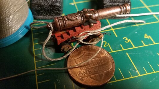
Started retraining my hands to rig tiny cannons, over a year since I did them on La Couronne. I don't remember them being this difficult. For this ship, no train tackles will be rigged, but breach ropes and gun tackles will be made. This time, the same size 2mm blocks will be used, but the addition of hooks will make the detail even better. I purchased brass etched 2mm block strops that come with built in hooks and eyes for all gun tackles, which will add detail while reducing the number of knots tied per carriage. These etched goodies come from HiS Model in Czech Republic, who is at the top of my favorite model merchants list with quick response to questions asked and wonderful service. The prices are good, and he has tiny parts for rigging no one else has, which is great for those of use who work in smaller scales like1:80, 1:84, or 1:100. Finding such tiny parts is not easy, and most kits have gun tackles that are 4-10 times their actual size, with blocks as large as the cannon trucks! Radimir at HiS Model did not ask for this promotion, but he certainly has earned it.

Here is a trial run making a gun tackle on one of the cannon of VII drakes with some of the 2mm hooks I got earlier from HiS Model.
371 Start Rigging the first Cannon Carriage.jpg

The idea is to get this tiny 35mm gun as close as possible to the proportions of this:
9-032-jpg.253809


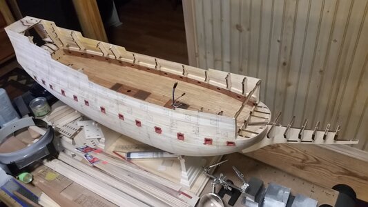
HMS Sovereign of the Seas hull
371 Progress So Far.jpg


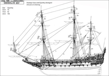
More planning... calculated the sizes and quantity of deadeyes for the shrouds and gammoning. The actual number, taken from Payne's engraving and Willem van de Velde's drawing, differs from the Sergal/Mantua model design. I just used the drawing as something to write on.
Deadeye Sizes and Quantity.jpg
 
Last edited:
Rigging sample looks excellent Kurt! I saw these photoetched parts (thanks for referring me to HiS) but didn't trust the block going into the closed strop - but obviously it does... I ended up tying knots with HiS 2.0 mm PE hooks - but your version is nice and clean and it has to be faster than what I did (not to be confused with fast - just faster). Awesome!
 
Crawling forward. The stern structure was partially assembled and test fit onto the hull frame. Before the side pieced are attached to the stern, the frames of the structure will be narrowed to a shape closer to that appearing in the Lely portrait of Peter Pett, also using measurements taken off Nigel's photos above as a guide. All of the individual magazine packs for the kit were opened and the instructions placed in binders on the bookshelf for reference. After looking at the cast metal decorations, they appear to have fine detail, mostly because they are a bit smaller than I expected. Their size indicated that few to none of the beautiful Amati cast decorations will fit on the DeAgostini model, which is disappointed because they are high quality. Since I also have the Amati plans, I wonder it I have the patience to make a second SotS model using them, when the DeAgostini model is finished? Some shortcut were noted in the rigging instructions while glancing through the magazines. The standing and running rigging are largely simplified, there are no triple parrels on the larger yardarms, only double rowed ones, and all the leech lines and bowlines are conspicuously missing, as are the nave lines for the parrels.

View attachment 195955

View attachment 195956
Are those the instructions? The Admiral said, "Are you serious?"
 
What can I say, John? I'm a glutton for information when I work on a project. I like to gather as much as I can before making the next step because it's hard to get a model ship accurate, or many times even half right. It's part of the work, and you change your mind when new information is found. How many model makers were disappointed when they learned their blue models of Wasa were supposed to red instead? We all try to get he best information we can, or we can just skip the research and make it easier by building models of ships that never existed like the Black Pearl or San Felipe. :D
Hey, I resemble that remark with the Black Pearl!
 
Rigging sample looks excellent Kurt! I saw these photoetched parts (thanks for referring me to HiS) but didn't trust the block going into the closed strop - but obviously it does... I ended up tying knots with HiS 2.0 mm PE hooks - but your version is nice and clean and it has to be faster than what I did (not to be confused with fast - just faster). Awesome!
I'm not confident about squeezing those tiny blocks into the strops without chipping or splitting the block. However, if the block does slip into the metal loop without breaking, and sits in the strop loosely, a bit of glue and some squeezing of the loop with a pliers will hold it in there. I'll let you all know how successful these block strops are so you can determine if they are worth using. At this scale, thread tends to fray or break if you work it too much, and CA glue can stiffen it to the point of breaking also. So, these strops will look cleaner and neater than thread if they work. Using just the hooks tied with thread to the blocks causes the overall tackle assembly to get longer. Each knot can add up to making the block and hook longer than the distance between the blocks at the end of each tackle. The whole tackle then looks way out of proportion. Since the hooks are part of the metal strop, the hook is close to the block, not one eye and one knots worth farther away. The tackle is more compact, and even if the blocks are oversized by scale, they tackle is not ridiculously oversized. Any way you work to rig these carriages, it's time consuming but adds more detail.
 
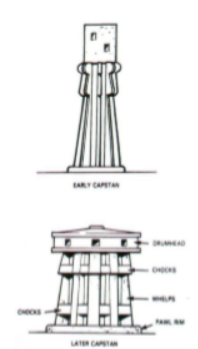
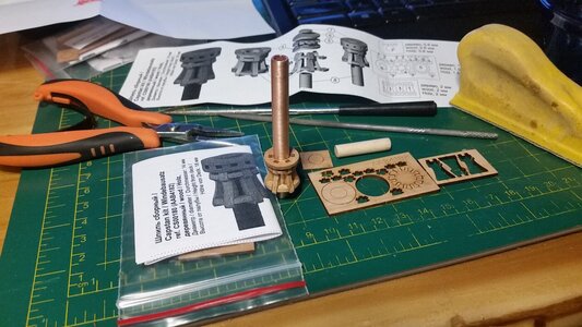
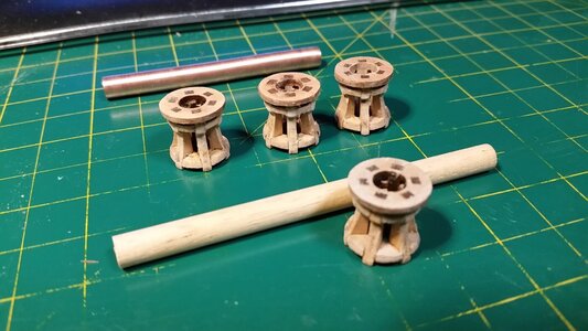
It's fun making detailed fittings from modifying kit parts, more so than scratch building them from nothing. It takes far less time. There are four capstan assemblies, three on the fore capstan and one on aft of the main mast. Four 16mm 19th century capstans kits made by Master Korabel and purchased from Craft Sailor Model Store in Canada will be modified to 17th century style capstans, known as "crabs".
1632456768741.png
On the fore capstan, the center shaft housing capstans on the lower, middle, and upper gun decks will not be wood. Instead, I found some spare 1/4" copper tubing in my plumbing supply box. It will be painted to match. Because it is hollow, it will solve the problem of how to route the electric lighting wires from the orlop deck up to the overheads of the lower and middle gun decks to power 6 LED lights on each deck, plus a third circuit that will light up the fore and stern castle LED's. These will simulated lanterns hanging from the deck beams overhead that will not be directly visible but offer indirect lighting. Holes drilled in the side of the hollow spindle will allow routing of the wires outa and along the overhead deck beams out of sight for each deck.

This crazy wiring arrangement is because I didn't run the wires through the bulwarks earlier in the build, and I'm creating a clever work-around. Below is a picture of the fore capstan spindle with the lower gun deck capstan fit to it. Wood stain and more details will be added later. The uppermost capstan on the upper gun deck will have the capstan head modified to take thee capstan bars through the head at three different elevations. This was a weaker design than the 19th century design in that the torque of the bars tends to split the head much easier.

372 Modify a 19th Century Capstan to a 17th Century One.jpg
 
It's fun making detailed fittings from modifying kit parts, more so than scratch building them from nothing. It takes far less time. There are four capstan assemblies, three on the fore capstan and one on aft of the main mast. Four 16mm 19th century capstans kits made by Master Korabel and purchased from Craft Sailor Model Store in Canada will be modified to 17th century style capstans, known as "crabs".
View attachment 257814
On the fore capstan, the center shaft housing capstans on the lower, middle, and upper gun decks will not be wood. Instead, I found some spare 1/4" copper tubing in my plumbing supply box. It will be painted to match. Because it is hollow, it will solve the problem of how to route the electric lighting wires from the orlop deck up to the overheads of the lower and middle gun decks to power 6 LED lights on each deck, plus a third circuit that will light up the fore and stern castle LED's. These will simulated lanterns hanging from the deck beams overhead that will not be directly visible but offer indirect lighting. Holes drilled in the side of the hollow spindle will allow routing of the wires outa and along the overhead deck beams out of sight for each deck.

This crazy wiring arrangement is because I didn't run the wires through the bulwarks earlier in the build, and I'm creating a clever work-around. Below is a picture of the fore capstan spindle with the lower gun deck capstan fit to it. Wood stain and more details will be added later. The uppermost capstan on the upper gun deck will have the capstan head modified to take thee capstan bars through the head at three different elevations. This was a weaker design than the 19th century design in that the torque of the bars tends to split the head much easier.

View attachment 257813
Fun can be found almost anywhere and any time . . . if you can recognize it. Getting possibly wound up in these looks like you found it. Rich
 
Are those the instructions? The Admiral said, "Are you serious?"
Yes, those binders are the instructions for the DeAgostini HMS Sovereign of the Seas. However, each binder only contains about 20 pages of heavily illustrated instructions. Much of the binder if filled with historical articles and how-to's using other models as examples. I'm convinced they spent as much money making the color magazines and binders as the laser cut plywood, wood strips, and cloth materials for the model itself.
 
Back
Top