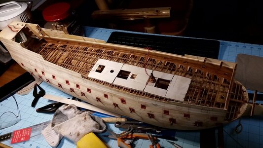
HMS Sovereign of the Seas - Bashing DeAgostini Beyond Believable Boundaries

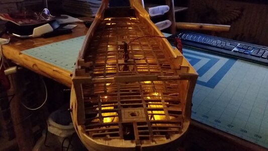
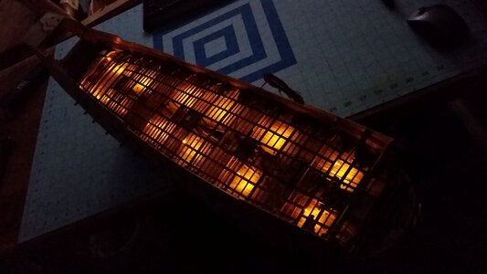
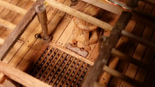
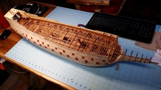
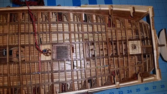
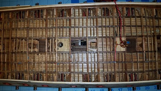
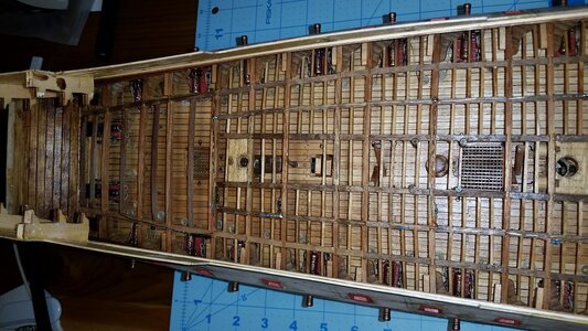
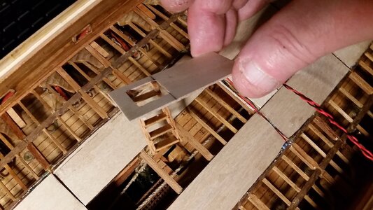
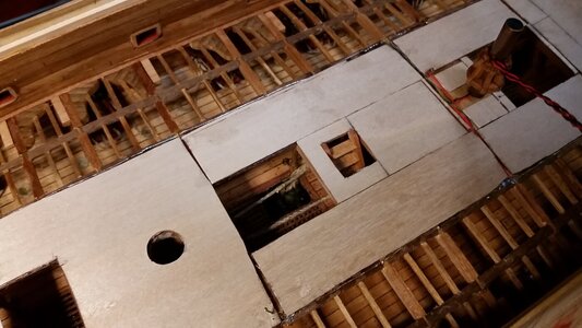
Lighting circuitry was started today. LED's are being installed to simulate lanterns hanging from the deck beams. Two lengths of 24 gage wire were stripped of insulation and laid down on top of the carlings. Small pieces of wire were bent to form staples, which were glued into holes that were drilled in the beams to hold the wires in the center of the carlings. The wires from the capstan shaft for lighting this deck were soldered to the two wires, the starboard wire connected to positive, and the port wire connected to negative. The two wires now formed a 3 volt electrical bus, and LED's are going to be connected between them. Each yellow nano LED has a resistor in its positive lead to reduce the current to a level that is safe for the LED to operate for about 11 years. Four of the LED's have been connected so far. The LED's and their wiring were soldered to the wires acting as bus-bars, and glued to the beams with PVA glue. Low temperature solder was used, so wood is not scorched while soldering.

Bending and cutting staples
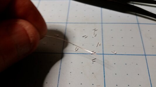
638 Making Staples for Holding Wires to Carlings.jpg

Staples are glued in drilled holes in the beams to hold the wire bus-bars.
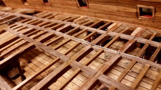
639 Strip 24g Wires and Overlay Carlings Using Staples and CA Glue.jpg

Two bus-bars installed, port is negative and starboard is positive.
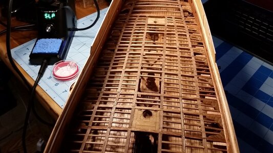
640 Negatove Wire on Left and Positive on Right.jpg

The leads of the LED's are routed over the beam, and LED resistors are positioned atop carlings or alongside beams.
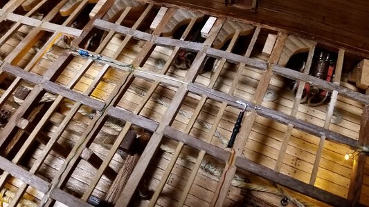
641 Solder LED's With Resistors Between Wires.jpg

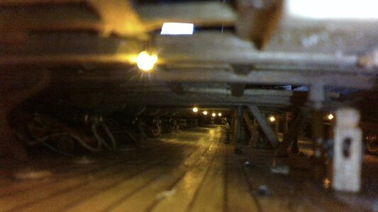
A test of the circuit is made, and surprisingly, it works! The first four LEDs illuminate the deck below.
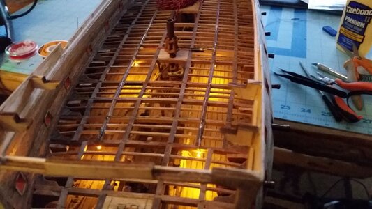
642 Test of First Four LED's.jpg
 
Hi friends!

Sorry for the re-post, but I thought my question would get more attention here. There are so many ways to display the anchors and anchor cables on model ships. I'm looking for advice from someone who knows a bit about anchors and their deployment. On my last model, I displayed all four anchors on the channels, each connected to their individual anchor cables. On my current model, I was thinking of displaying the forward bower anchor as shown below, in the process of being retrieved and hanging from the cathead hook. The anchor behind it would be stored as the one on the right, lashed to the anchor to the channel. Why there already is a forward bower anchor on the channel, I have no idea. There is no place left to store the anchor they are currently weighing! Keep reading below, I'm just getting to my question. .
1644096727457.png


As you can see, the port forward anchor line is rigged with a messenger (vyol line) as if the anchor is being lifted. The starboard forward anchor cable has a turn round the bitt and stoppers holding it to the deck, and its anchor will be stored on the channel.
552 Installed Hanging knees in Lower Deck Bow Section.jpg


Question: were the aft anchor cables often left attached to their anchors while those anchors are stored on the channels? If so, would have to run more cables on the deck and run them down the main hatch and down to the orlop deck, and those extra cables would clutter the deck up quite a bit, interfering with the anchor weighing operation in progress for the port forward bower anchor. Should I run a second cable for the after starboard anchor and leave the after port anchor with no cable attached? Looking for some opinions here guys....1644143738763.png
Please help.
 
Last edited:
Hello Kurt, The answer will be a bit longer than expected but here is what I dig, according to Brian Lavery.

Stowage of the Cables

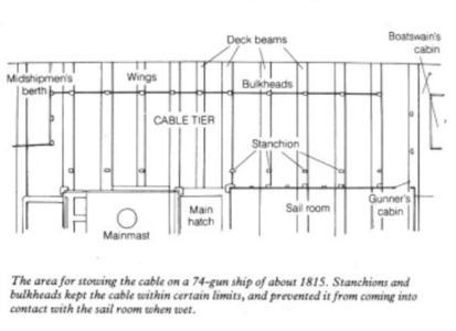
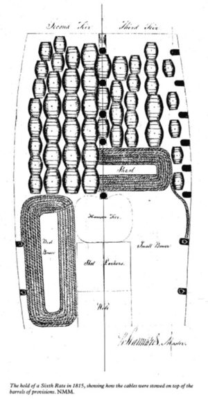
In 1670 the cables of a First-Rate weighed from 36 to 45tons, and those of a Third Rate from 15 to 18 tons. The seven 22in cables of a 74-gun ship of 1795 had a volume of more than 1300ft. Clearly, a large amount of space was needed in which to stow them, the cables were wet when brought up so it was desirable to have them low in the ship, where they could drain into the bilges. On the other hand, they had to be ready for use when necessary and could not, for example, bestowed under the barrels of provisions in the hold. On two, and three-decked ships, they were therefore stowed on the orlop deck. They were laid in enormous coils, some on each side of the row of masts, capstan steps, sail rooms, pump well, and hatchways that ran down the centerline of the ship. The area they occupied was about two-fifths, of the total length of the ship. On a 74-gun ship of about 1800, it measured 70ft long, 6ft high, and at least 12ft wide on each side.

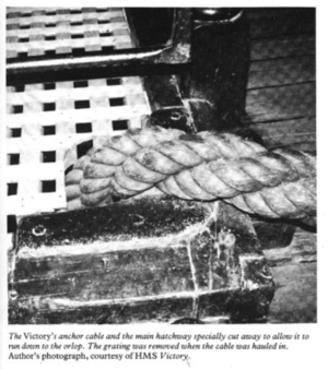
After about 1755, this part of the orlop was not planked in the usual fashion. Instead of planks that ran over the tops of the deck beams, those of the cable tier were made in short lengths, and each was fitted between two beams, into recesses cut for the purpose in the top corners of the beams. The short planks were removable, and this system allowed water from the cables to drain into the hold, and thus find its way to the well, where it could be pumped out. Stanchions and light bulkheads were erected to keep the cables in position, and in particular away from the sail rooms, where wet cables might damage the sails.

1644164120906.png 1644164142515.png

1644164760513.png

Fixing the Cable to the Anchor

The cable was removed from the anchor if the ship was not close to any hazard which might necessitate its use. This allowed the hawsehole to be plugged to prevent the of water in a heavy sea. When the anchor was likely to be needed, the cable was bent through its ring and looped over itself. The loop was then seized with several bends of twine. This form of the noose was made which tightened around the ring as the pull on the cable increased.
Naturally, the hawse holes had a tendency to let water in a heavy sea. They could be blocked by means of the hawse bag; canvas bags filled with oakum which could be stuffed in around the cable. These were not totally waterproof and had to be removed when the cable was being hauled in. To limit the spread of water, the manger was erected on the deck just aft of the hawse holes.

I can conclude that in the sea, where anchor doesn't immediately need, the cables were not attached and exposed thru the hawse holes as they were plugged. As Stephan mentioned, If you would show sails on your model (even some), that means your ship is not staying\mooring.

Hope this will help,
 
Hello Kurt, The answer will be a bit longer than expected but here is what I dig, according to Brian Lavery.

Stowage of the Cables

In 1670 the cables of a First-Rate weighed from 36 to 45tons, and those of a Third Rate from 15 to 18 tons. The seven 22in cables of a 74-gun ship of 1795 had a volume of more than 1300ft. Clearly, a large amount of space was needed in which to stow them, the cables were wet when brought up so it was desirable to have them low in the ship, where they could drain into the bilges. On the other hand, they had to be ready for use when necessary and could not, for example, bestowed under the barrels of provisions in the hold. On two, and three-decked ships, they were therefore stowed on the orlop deck. They were laid in enormous coils, some on each side of the row of masts, capstan steps, sail rooms, pump well, and hatchways that ran down the centerline of the ship. The area they occupied was about two-fifths, of the total length of the ship. On a 74-gun ship of about 1800, it measured 70ft long, 6ft high, and at least 12ft wide on each side.

After about 1755, this part of the orlop was not planked in the usual fashion. Instead of planks that ran over the tops of the deck beams, those of the cable tier were made in short lengths, and each was fitted between two beams, into recesses cut for the purpose in the top corners of the beams. The short planks were removable, and this system allowed water from the cables to drain into the hold, and thus find its way to the well, where it could be pumped out. Stanchions and light bulkheads were erected to keep the cables in position, and in particular away from the sail rooms, where wet cables might damage the sails.

View attachment 288961 View attachment 288962

View attachment 288963

Fixing the Cable to the Anchor

The cable was removed from the anchor if the ship was not close to any hazard which might necessitate its use. This allowed the hawsehole to be plugged to prevent the of water in a heavy sea. When the anchor was likely to be needed, the cable was bent through its ring and looped over itself. The loop was then seized with several bends of twine. This form of the noose was made which tightened around the ring as the pull on the cable increased.
Naturally, the hawse holes had a tendency to let water in a heavy sea. They could be blocked by means of the hawse bag; canvas bags filled with oakum which could be stuffed in around the cable. These were not totally waterproof and had to be removed when the cable was being hauled in. To limit the spread of water, the manger was erected on the deck just aft of the hawse holes.

I can conclude that in the sea, where anchor doesn't immediately need, the cables were not attached and exposed thru the hawse holes as they were plugged. As Stephan mentioned, If you would show sails on your model (even some), that means your ship is not staying\mooring.

Hope this will help,
Thanks Jimsky! I was aware of the storage of cables as you described but the key for me was knowing how often and under what conditions the other anchors would be disconnected from the anchor cables, and the cables stored below. I was also aware of the bags of oakum used to block water from entering the hawse pipes, but I understood those to be placed in the hawse pipe while a cable was passed through the hawse pipe and connected to an anchor ring. I assumed that fitted plugs would be used in an empty hawse pipe. Does this agree with what you've read?

Suffice to say, your description of the use of anchor cables means that on my model only once anchor will be attached to its cable on each side of the ship. This is mostly because anchor weighing operations simulated on the port would be hampered by having another cable on the deck. I could have a second anchor connected on the starboard side, but I will choose not to for the same reason. It would make it more difficult for the crew to use the vyol line and raise the port anchor. This helps a lot, Jimsky! Thanks! I still have no idea why Payne illustrates one anchor being raised while two others are already stored on the portside channel. Maybe the engraving was trying to show too much in the way of details, an issue I am running into making my own model! :D
 
I assumed that fitted plugs would be used in an empty hawse pipe. Does this agree with what you've read?
Yes, agree.
I still have no idea why Payne illustrates one anchor being raised while two others are already stored on the portside channel. Maybe the engraving was trying to show too much in the way of details, an issue I am running into making my own model! :D
maybe is Payne showing the ship mooring and anchor is ready to displaced in the water? Take a look at the right anchor. The cable attached to it is as twice thinner as it is on the left one... both are bowers (the largest anchors). The painting is art, it was known that oftentimes painters make their paintings without seeing the actual ship. ;) They have their own Artistic license...
 
I think this is the same story like the canons and their rigging. They show to much rope which is not in use to ship conditions.
 
I think this is the same story like the canons and their rigging. They show to much rope which is not in use to ship conditions.
Yes, it appears as if the Payne wanted to show the anchors in both storage locations on the channel and being weighed at the same time. Curiously, Doris Obručová's model of HMS Sovereign of the Seas copies the same anchor configuration as Payne's engraving. I really don't think you'd have three bowers on the same side of the ship. I have not seen any sources that show it, but I'm wondering, did the Sovereign ever had a kedge anchor stored on the main channel?
 
I still have no idea why Payne illustrates one anchor being raised while two others are already stored on the portside channel. Maybe the engraving was trying to show too much in the way of details, an issue I am running into making my own model! :D
Oh...there is something else that brought my attention to Payne's paintings. The haws holes, in this perspective of the ship, we shouldn't see the howse holes they are should be parallel to the keel(not perpendicular) as shown in the painting.

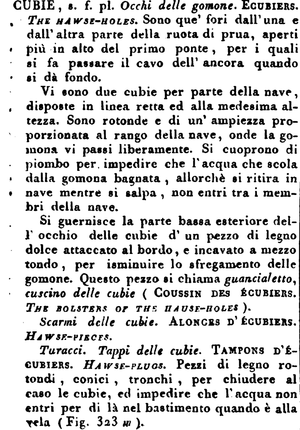
Hawse Holes
The cables entered the hull through the hawse holes. Normally there were four of these, in the foremost part of the hull, where the curve of the bows meant that they would face forward rather than to the side. The timbers in this area, known as hawse pieces, were fitted parallel to the keel rather than perpendicular to it. On most ships, there were four holes, two on each side, of which one was for the main anchor. Usually, they were all on one level, but on some seventeenth-century ships, such as those shown in Deane's Doctrine the outermost pair was higher than the inner one.

The position of the hawse holes determined that of the capstans, bitts, and other anchor gear. The hawse holes were not situated on the orlop deck where the cables were stowed as they would have been too near the waterline, where the sea could have entered the ship too easily. On full two-decker, they were situated just above the lower deck and the cable was brought in at that level. On early eighteenth century Sixth Rates, where the lower deck was only partly armed, they were nevertheless placed at lower-deck level, perilously close to the waterline. On the ‘true frigates' of the mid-eighteenth century, the lower deck was even lower, and after the first generation of these vessels, the hawse holes were positioned just above the upper deck. On the smaller ships, there was little choice, and the hawse holes were at the level of the main deck. In most cases hawse holes were positioned slightly above the level of the deck concerned, to give a suitable lead to the capstan.

Hawse holes had to be rather bigger than the cables intended to path through them. A 74-gun ship of 1795 used a cable of 22in circumference and 7in diameter, so the haws holes were 15in in diameter,

After 1811 when chain cable was first being tested, hawse holes had to be lined with iron. There is some evidence that this may have been done for many years before, using the lead.
 
Oh... c'è qualcos'altro che ha attirato la mia attenzione sui dipinti di Payne. I fori, in questa prospettiva della nave, non dovremmo vedere come sono i fori dovrebbero essere paralleli alla chiglia (non perpendicolari) come mostrato nel dipinto.

Buchi di Hawse
I cavi sono entrati nello scafo attraverso i fori di falco. Normalmente ce n'erano quattro, nella parte più avanzata dello scafo, dove la curva della prua significava che sarebbero stati rivolti in avanti piuttosto che di lato. I legni in quest'area, noti come pezzi di hawse, erano montati parallelamente alla chiglia anziché perpendicolarmente ad essa. Sulla maggior parte delle navi c'erano quattro fori, due su ciascun lato, di cui uno era per l'ancora principale. Di solito erano tutti su un livello, ma su alcune navi del diciassettesimo secolo, come quelle mostrate nella Dottrina di Deane, la coppia più esterna era più alta di quella interna.

La posizione dei fori di falco determinava quella degli argani, delle bitte e di altri attrezzi di ancoraggio. Le buche di falco non erano situate sul ponte orlop dove erano stivati i cavi in quanto sarebbero stati troppo vicini alla linea di galleggiamento, dove il mare avrebbe potuto entrare troppo facilmente nella nave. Su due piani pieni, erano situati appena sopra il ponte inferiore e il cavo veniva portato a quel livello. All'inizio del diciottesimo secolo, dove il ponte inferiore era armato solo in parte, erano comunque collocati a livello del ponte inferiore, pericolosamente vicino alla linea di galleggiamento. Sulle 'vere fregate' della metà del Settecento, il ponte inferiore era ancora più basso e, dopo la prima generazione di queste navi, le buche di falco erano posizionate appena sopra il ponte superiore. Sulle navi più piccole c'era poca scelta e le buche di falco erano a livello del ponte principale.

I fori di Hawse dovevano essere piuttosto più grandi dei cavi destinati a passarci attraverso. Una nave da 74 cannoni del 1795 utilizzava un cavo di 22 pollici di circonferenza e 7 pollici di diametro, quindi i fori di haws avevano un diametro di 15 pollici,

Dopo il 1811, quando il cavo della catena fu testato per la prima volta, i fori di Hawse dovettero essere rivestiti di ferro. Ci sono alcune prove che ciò potrebbe essere stato fatto per molti anni prima, usando il piombo.
1644181112028.png
 
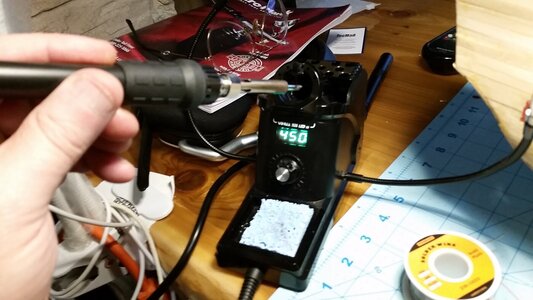
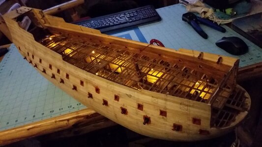
I never soldered before this project, only oxy-gas, arc, and TIG welded. Doing this really raised my confidence. The rest of the LED's were soldered in for the lower gun deck lighting today. Low temperature solder with rosin worked the best. I tried using hard tin solder with very little lead and had trouble getting it to stick, but once I changed solder, it because extremely easy to coat wires and connect them with soldering, even working inside the ship in cramped areas. The lighting was tested and it worked! I took more pictures in a dark room with the LED's on using the borescope, but need to transfer the photos later for posting, after I get a SIM card reader.

Inexpensive soldering station
643 Soldering Station.jpg

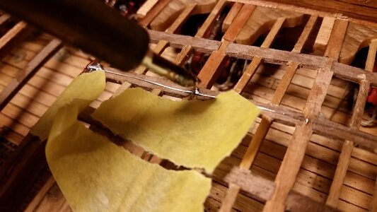
Wires held with masking tape were quickly and easily soldered to the bus-bars.
644 Soldering LED Wires to Bus-Bars.jpg

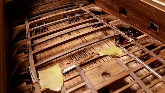
PVA glue was used to hold wires in place.
645 Last Joint Soldered.jpg

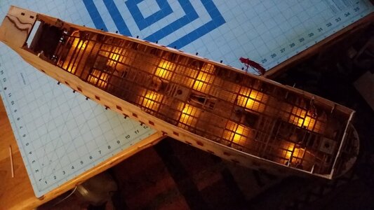
Light test!
646 Light Test.jpg

647 Light Test.jpg

648 Light Test.jpg

Great success!
649 Progress So Far.jpg
 
COOL! That looks fantastic Kurt! I created workarounds when I needed to (should have) soldered things. Perhaps on a future build. Your success is encouraging to me.
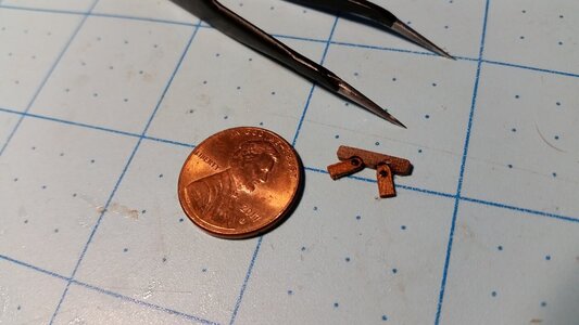
So did I. Looped brass items like rings and chain plate parts are looking less scary to solder closed. I think my guess at setting the temperature of the soldering iron is correct because the solder readily melted and flowed well and any wood underneath didn't get scorched. Soldered brass parts will blacken completely, hiding solder spots.
 
Nice job!
About the question about the anchors: Did you have look at John Harlands book: Seamanship in the Age of Sail. I could never do without it. Full of answers for questions you were not even up to asking.
 
Nice job!
About the question about the anchors: Did you have look at John Harlands book: Seamanship in the Age of Sail. I could never do without it. Full of answers for questions you were not even up to asking.
I did purchase that book on your recommendation. Thanks!

This is the only book I have that does a thorough job describing the operations of how to sail a full rigged ship, including methods for anchor handling, sail drying, boat launching and recovery, sailing in storms, and a whole lot more. The handling and use of individual sails is discussed. If you want to understand how to sail a ship, this book is a great start.
 
Back
Top