HMS Sovereign of the Seas - Bashing DeAgostini Beyond Believable Boundaries

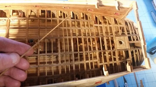
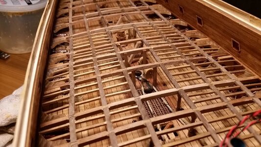
The carlings for the middle gun deck were finished, and installation of ledges made from 1.5x1.5mm sticks of wood was begun at the bow.

The edges of the beams are beveled with a diamond file. I prefer diamond files to wood mill files because they are easier to clean and don't load up with wood flour nearly as much.
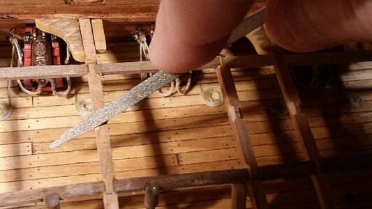
603 Filing Bevels in Beams for Carlings.jpg

All beams prepared for carlings by beveling.
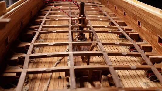
604 Beam Bevels Filed.jpg

Measure and cut 1x3mm walnut pieces and bevel the ends for each carling.
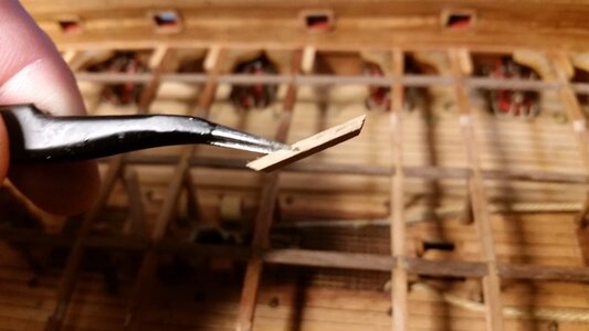
605 Measure and Shape Calrings.jpg

Carlings are glued in place with PVA glue. Tweezers are useful here.
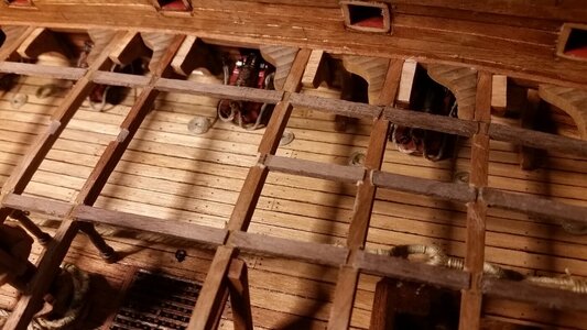
606 Install More Carlings.jpg

Once all carlings are done, it's time to prepare wood for making ledges, which are oriented in the transverse direction to the hull. Inexpensive 1.5x1.5mm basswood sticks are stained with dark walnut Danish Oil, cut to length and installed one at a time with PVA glue. The process goes faster than you think.
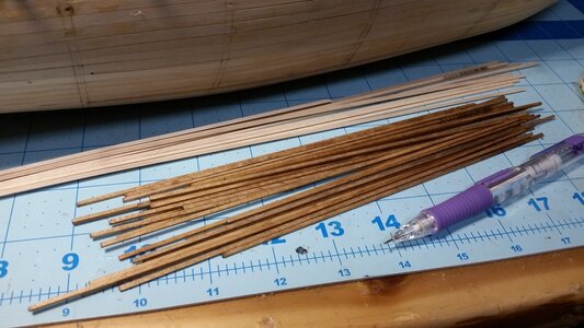
607 Stain Basswood for Ledges.jpg

Starting at the bow, basswood sticks are glued in place, using McCay's drawing of the middle gun deck supports as a guide. Several rows were installed with more to come.
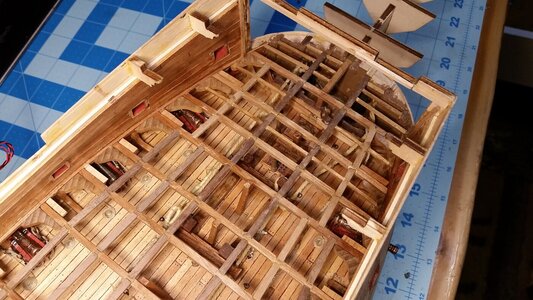
608 Begin Installing Ledges at the Bow.jpg

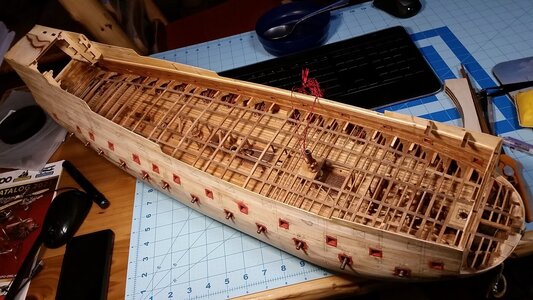
Progress so far. Some may think it's insane to cover all this work with a deck, but building all these details is a fun learning experience. It's not hard to do, since gluing little sticks together was a great pastime of mine in 3rd grade. :D Had lots of practice since then. . .
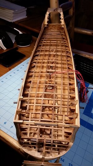
609 Progress So Far.jpg
 
Last edited:
More details. These had to be done before access to the lower gun deck was crowded out. After looking at Payne's copper engraving and Willem van deVelde's illustration closely, it was apparent that the mizzen mast needed to be move a bit farther aft, otherwise there would be too little room between it at the railing forward of it in the bridge deck later in the build. Checking build logs from Nigel and another build log of the DeAgostini model built per its original instructions, it was confirmed that the mizzen mast had to be moved. This also places the mizzen in a more proper position relative to where the channels go and relative to the gun portals for the upper gun deck. So, I went into destruction mode again and bored a new hole in the deck and plugged the old hole, which turned out not to be necessary because reinforcement timbers needed to cover that portion of the deck anyway.

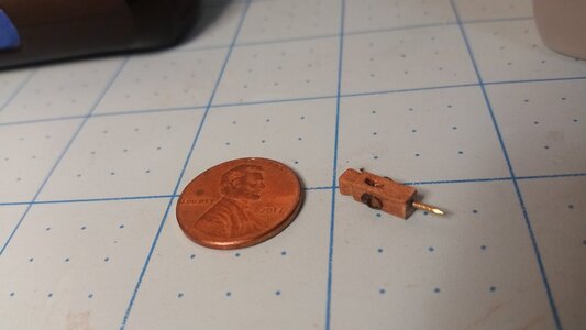
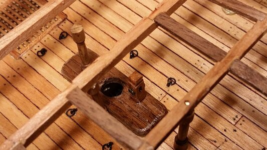
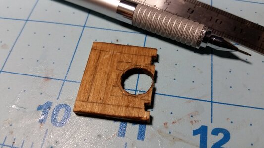
The reinforcement was made with strips of walnut, and support columns were also installed using McKay's deck diagrams as a guide. A small knight's head was fashioned from a piece of 3x3mm walnut, rings installed on it, and it was mounted on the deck with a brass pin to reinforce the joint. This is supposed to be for the tie which hauls up the lateen yardarm. I assume McKay runs the tie down three deck because there was insufficient room on the poop deck for enough sailors to haul the yardarm up. Moving the mast father aft may help this. If I decide to later move the knight's head up to the poop deck, I'll just break it off, save it, and reinstall it up there, but first I have to figure out what McKay was thinking putting it way down on the lower gun deck. It doesn't make sense to me yet. Anyone have thoughts on this? Examples from other ships perhaps?

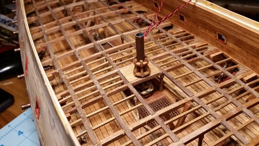
Moved mizzen mast farther aft.
612 Move Mizzen Mast Hole Farther Aft.jpg

613 Added Reinforcement Around Mizzen Mast Hole.jpg

Small knight's head
614 Make a Knight's Head.jpg

615 Install Knight's Head Forward of Mizzen Mast.jpg
 
Kurt, how do you maintain such a consistent run of the carlings in the fore/aft curve? I have seen many builds are a bit jagged, do you eyeball the line of the beam notches or measure and let the natural curve of the hull maintain it? It seems that even if a notch is .5mm off it would be noticeable- yes? Oh, awesome joinery btw….
 
Kurt, how do you maintain such a consistent run of the carlings in the fore/aft curve? I have seen many builds are a bit jagged, do you eyeball the line of the beam notches or measure and let the natural curve of the hull maintain it? It seems that even if a notch is .5mm off it would be noticeable- yes? Oh, awesome joinery btw….
Truth be told, I do all the ledges by eye. However, to line up the carlings, only three line segments for each carling strake were drawn from fore to aft on the top surfaces of the beams, a forward line segment, then a middle segment at a slight change in angle, then an aftermost line segment. I didn't even bother to make curves. The two inboard lines of carlings were first, since they are perfectly parallel to the centerline. Let' take the starboard side carlings for example. Using McKay's layout as a guide, the second carling line is drawn for the outer most carling closest to the the bulwark, adjusting the curvature to match the changing distance from this carling to the bulwark. The last carling lies directly between the first two. Mirror this arrangement on the port side of hull.

As far as keeping the line segments of each piece of wood straight, that comes with staying along the pencil lines on the beams, and taking care to do each one slowly and checking for alignment by eye before moving on. No tricks here. The small bevels filed on the edges of the beams are also done by hand, and follow the pencil lines. Up close there are small imperfections, but sizing and placement of the wood segments with PVA glue went at steady pace. It got a bit crowded at the rear to be sure, but using tweezers to set the segments of the carlings in place and then using your fingers to wipe off excess glue and feel if the segment was flat and even between two beams is all it took. Up close there are imperfections, but the overall effect is close enough. Sometimes I filed the bevel on a beam too wide. If a segment seems to create a zig-zag in the overall line of a carling, it was corrected immediately, especially if the alignment was off by a very noticeable 0.3mm. Many hours are still going into finishing the ledges before I sand the lumps and imperfections on the top surface of the entire structure, throw down pieces of plywood, arrange the wiring for the LED lights for the lower gun deck, then plank over the false deck with tanganika strips and move on the next deck up. You can't hurry the process, and listening to music or YouTube videos keeps you from losing interest while you work through the tedium. After about 7 days of solid work, the deck is finished.

I still have to figure out how to mount a mirror on the endoscope such than the wide angle lens of the camera cannot see the edges of the mirror, and drill one or possibly two vertical holes straight through the hull for the camera to move through.

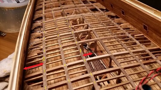
Pencil marks on the beams are highlighted in yellow. Arrow show the measuring direction for locating the positions of the carlings. Numbers indicate the order of installing the carlings.
629 Carling Layout Measurement.jpg

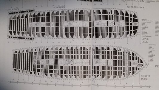
Jon McKay's deck support plans. The middle gun deck, which is in progress, is labeled by McKay as the Second Deck and is the lower diagram below.
630 John McKay's Second Deck (Middle Gun Deck) Plan.jpg
 
Last edited:
Hi Kurt, you could consider leaving off some deck planking Admiralty style.
Departing from the vision I have for this model and going full Admiralty is a drastic change in direction, especially since the Admiralty style leaves off so much rigging. Also, I can't see you that would help for a deck that is buried two decks down. You'd have to leave a section of the upper gun deck off, and that means some piece of deck equipment has to go. My aim was to make a complete model, with sails and everything and live up to the title of this thread. The camera has the virtue of being hidden. It can be fed in through a hole in the bottom, and remain unseen under the cabinet that the ship will be in. Adding internals started off with the intent of just having some details on the inside visible from the gun ports to create the illusion that the ship was complete inside and outside. Things got out of control, and now the lower gun deck looks as detailed as some weather deck on other people's models. Why? Well, it got to be too much fun, and making details from sticks of wood was not overly difficult from a skill standpoint and it looks really nice after a few days of work. It only need a few shortcuts, like making knees from wooden molding, and time and patience. Precision in sanding the sticks to the correct length is essential, which works because my personality is detail oriented. I'm still envious of Paul's painting because it parallels my delight in making the small stuff as correct as possible. So, when the ship is done, it has so many details that you can gaze at it like a crow with a shiny object for 20 minutes and still not take it all in. I know many out there love cutaway models. I just can't take a bite out of the side of the hull. It seems incomplete to me. I could continue to add details to this deck, since the ones in place currently are only the very basic features, but the camera would not be able to see them. So, it's best to leave it where it's at and move on to the next deck. What would be really cool is making the stern cabin interiors like Doris Obručová did. She did extraordinary work on the stern cabins on her model, and they have the advantage of being visible through the windows on the galleries, creating the illusion of the complete ship which I am seeking. The nice part is that the build is moving slowly, but it's a lot more fun, and a good part of that is the discussions with you, Paul, and all the others who are following the build. Heck, just picking on Paul while he builds Wasa is fun all by itself. :D

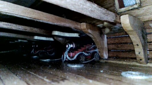
Camera test run and steak peek of how I want to view the internal decks... like a tourist walking in HMS Victory. This truly stirs my imagination. If I drill 2-3 holes up through the bottom, the camera would be capable of seeing the ship from these locations, 360 degrees around.
575 Endoscope View.jpg
 
Last edited:
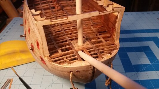
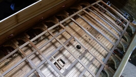
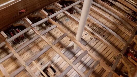
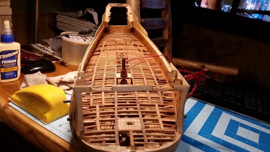
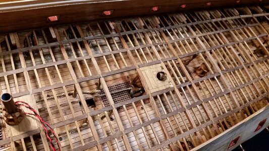
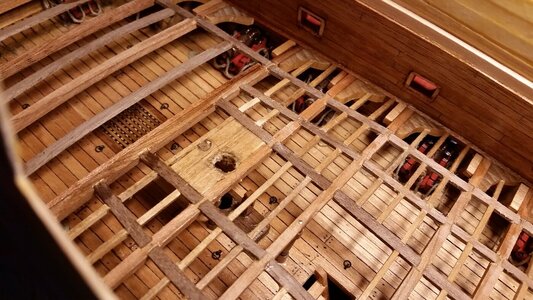
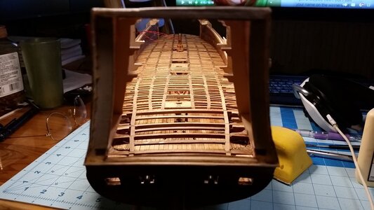
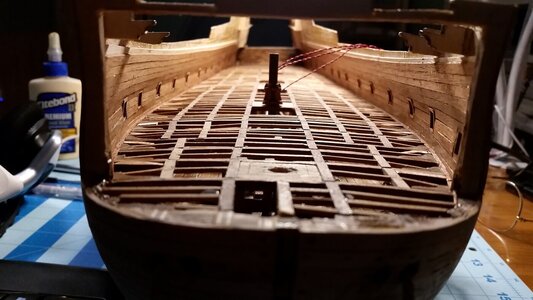
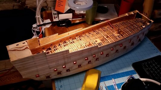
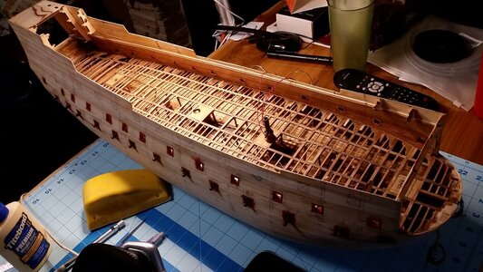
The final ledges were installed, along with the timbers that support the mizzen mast. The dowel for the mizzen mast was used to check alignment of the holes. The foundation for the middle gun deck is finished! After a light sanding to even out a few bumps, the false deck will be glued over the top of this, lighting installed, and after holes for the endoscope camera are drilled through the hull and lower gun deck. After playing with little sticks and glue, it's time for a break.

633 Finished Ledges and Mizzen Mast Reinforcement.jpg

634 View From Stern.jpg

635 View From Bow.jpg

636 FInished Middle Gun Deck Supports.jpg

637 Progress So Far.jpg
 
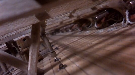
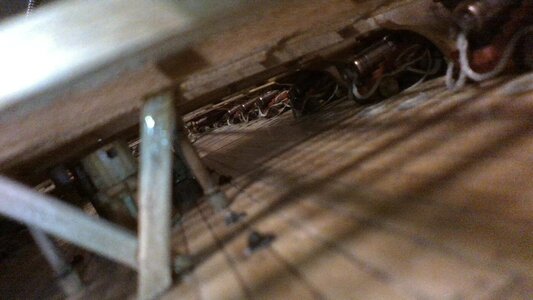
I'm still playing around with different cameras, including two borescopes and a webcam to see which will work inside the dark deck of a ship. All cameras need more light than I expected, perhaps more than can be made available using LED's. This is a photo taken with a Kano webcam, using ambient light allowed to enter through the deck structure above. Most inexpensive spy cameras available on Amazon don't have a low enough light rating in lux to do well in dark areas, and pictures come out very grainy. This is how it looks with plenty lighting. All three of the cameras I've tried have a fixed focal length, so adjusting the focus is not possible. Borescopes are great at focusing on close objects, but poorly past 8 cm. This webcam can focus near or far, having a lens that has to be moved over the camera physically. If anyone has any suggestions, let me know.

Webcam with near focus lens
WIN_20220131_20_51_59_Pro.jpg

Webcam without near focus lens
WIN_20220131_21_13_11_Pro.jpg
 
Last edited:
Back
Top