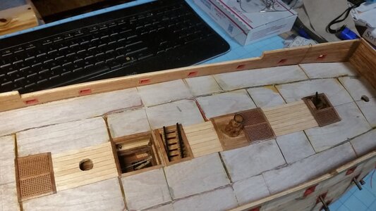
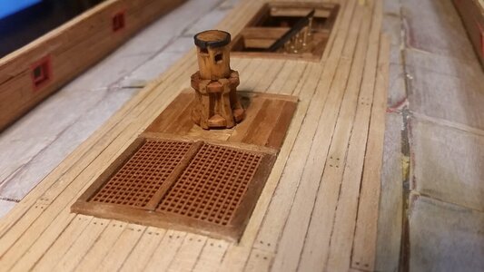
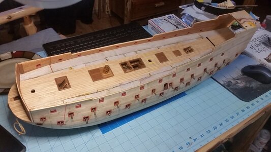
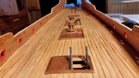
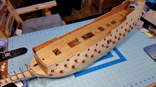
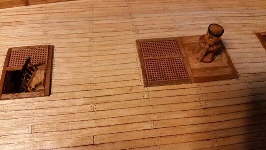
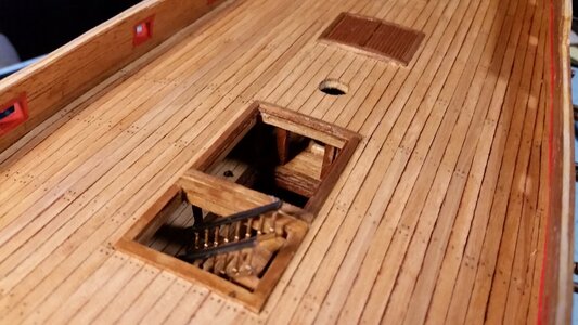
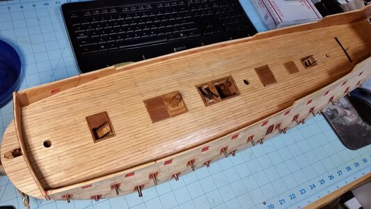
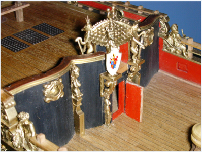
Very elegant reproduction of the stairs Kurt. Fitting for this ship. Congratulations on your clever solution.
-

Win a Free Custom Engraved Brass Coin!!!
As a way to introduce our brass coins to the community, we will raffle off a free coin during the month of August. Follow link ABOVE for instructions for entering.
-

PRE-ORDER SHIPS IN SCALE TODAY!
The beloved Ships in Scale Magazine is back and charting a new course for 2026!
Discover new skills, new techniques, and new inspirations in every issue.
NOTE THAT OUR FIRST ISSUE WILL BE JAN/FEB 2026
You are using an out of date browser. It may not display this or other websites correctly.
You should upgrade or use an alternative browser.
You should upgrade or use an alternative browser.
HMS Sovereign of the Seas - Bashing DeAgostini Beyond Believable Boundaries
- Thread starter DARIVS ARCHITECTVS
- Start date
- Watchers 105
Gratings and stairways look incredible Kurt - clever sourcing for the bannisters.
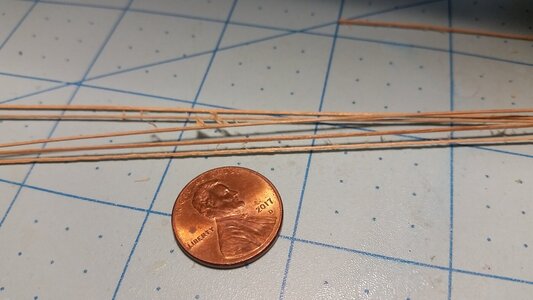
Hi Kurt, this might have been answered in other build posts but how does the Sharpie pen ink stain hold up once you use a finish for your deck planks? Is it the permanent type Sharpie? Thanks.The evening was spent mass producing 80mm tanganika deck planks. Because 4mm wide tanganika strips were not available, 5mm strips were ripped with a bandsaw to 4mm. A mechanical pencil and a jig was used to speed up the process of marking the trenails on the ends of the planks. A brown Sharpie pen was used to stain one edge of each plank, which is sufficient to create the effect of the tar sealed seams, and long as all the planks are oriented with the darkened edge in the same direction.
View attachment 318358
I’m enjoying your build and posts, lots of great information.
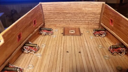
The Sharpie is a permanent marker. I use the brown one since the black offered too much contrast, and I only mark one side each plank, not both, or the lines on the deck become too prominent. If the stain of the edges were to fade a bit with time, that would actually work to your advantage by making the lines more subtle. Below is a good example of the results. The lines are not as smooth as on many models, owing to the unevenness of the wood grain, and the propensity of the marker dye to soak into the wood if you apply too much, and the effect suggests variation on the seam widths. Keep in mind these are 4mm wide planks. If you require smoother and even lines, there are other methods. This method is quick and dirty.Hi Kurt, this might have been answered in other build posts but how does the Sharpie pen ink stain hold up once you use a finish for your deck planks? Is it the permanent type Sharpie? Thanks.
I’m enjoying your build and posts, lots of great information.
Last edited:
The Sharpie is a permanent marker. I use the brown one since the black offered too much contrast, and I only mark one side each plank, not both, or the lines on the deck become too prominent. If the stain of the edges were to fade a bit with time, that would actually work to your advantage by making the lines more subtle. Below is a good example of the results. The lines are not as smooth as on many models, owing to the unevenness of the wood grain, and the propensity of the marker dye to soak into the wood if you apply too much, and the effect suggests variation on the seam widths. Keep in mind these are 4mm wide planks. If you require smoother and even lines, there are other methods. This method is quick and dirty.
View attachment 318992
Thanks Kurt, as always a helpful response based on your experience. It was the issue of the ink running into the grain of the planks I was wondering about.
I guess it’s a matter of experimenting with different methods, finishes and woods.
Yes, you have to choose what you like. I really don't do a lot of experimenting and use simple processes, so my results are not tip top, but they work.Thanks Kurt, as always a helpful response based on your experience. It was the issue of the ink running into the grain of the planks I was wondering about.
I guess it’s a matter of experimenting with different methods, finishes and woods.
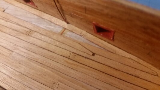
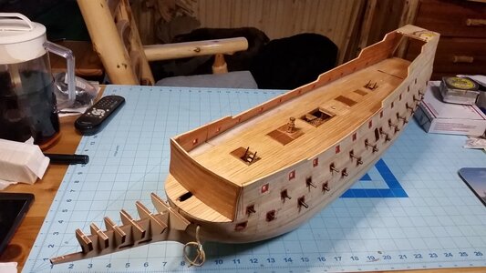
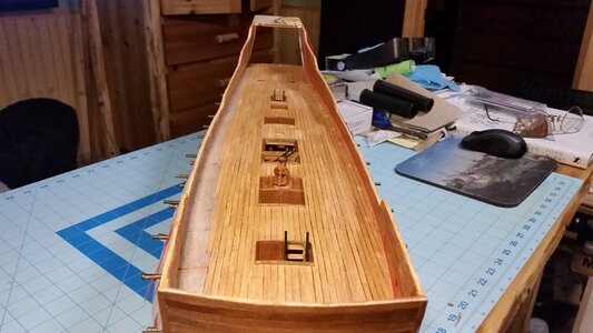
Got a lot of planking done today while watching the Horatio Hornblower series again. Not surprised that it's going faster after doing the two decks below it for practice. There are only a few more strakes left on the starboard side, including margin plank, which takes the longest. The plank sections of the deck were scraped with a hand scraper holding a razor blade to even all the plank edges out. Two stern castle frames were reduced in size also, which makes it easier to get my fingers in there when it's time to work on the stern quarters.
More DESTRUCTION!
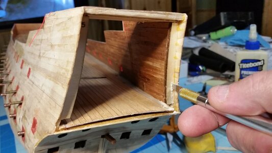
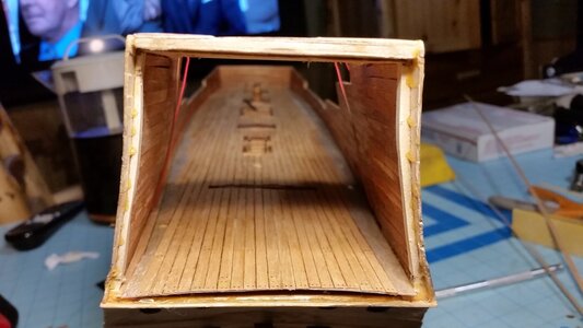
Fitting deck plank ends into the margin plank takes a lot of time. The faint pencil line on the margin plank shows where the margin plank will be cut away to acep the end of the loose deck plank.
Progress so far.
More DESTRUCTION!


Fitting deck plank ends into the margin plank takes a lot of time. The faint pencil line on the margin plank shows where the margin plank will be cut away to acep the end of the loose deck plank.

Progress so far.


Last edited:
Sometimes when you make a mistake, you need to come up with a clever repair. During deck planking, the positive wire for the lighting if the forecastle broke off under the deck. Instead of ripping up the deck and repairing the wire, the positive wire for the sterncastle would provide voltage for the forecastle LED's. To do this, a new wire was run along the edge of the deck from the stern. This wire needed to be hidden, so the waterway was placed over the top of it.
The waterways were mays from 1mm strips of tanganyika wood left over from cutting 5mm strips down to 4mm strips. I'm glad I saved these scraps, because they are perfect to make scale waterway strips. A green Scotchbrite pad and a sanding block was used to strip the dangling fibers from the strips. Then PVA glue was used to glue the waterway strips in place, and Q-tip cotton swabs were effective at cleaning out excess glue from the corner where the deck meets the bulwark. This was delicate work, but the result looks good.
The end of the waterboard strip was anchored to the deck with PVA glue before proceeding to glue the rest of the strip.
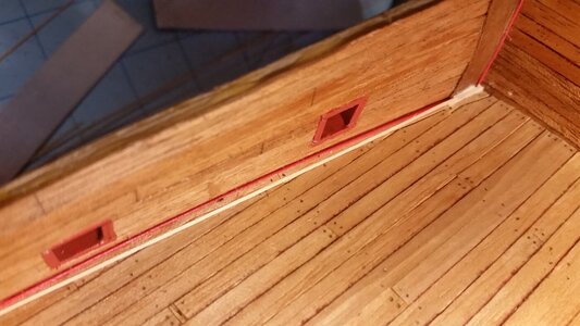
Finished waterboard on the port side.
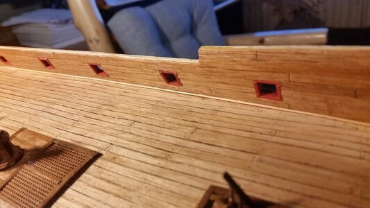
Finished waterboard on the starboard side.
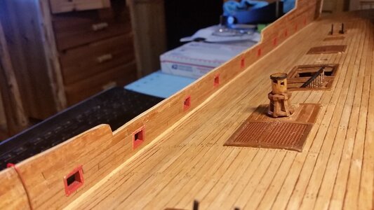
The waterways were mays from 1mm strips of tanganyika wood left over from cutting 5mm strips down to 4mm strips. I'm glad I saved these scraps, because they are perfect to make scale waterway strips. A green Scotchbrite pad and a sanding block was used to strip the dangling fibers from the strips. Then PVA glue was used to glue the waterway strips in place, and Q-tip cotton swabs were effective at cleaning out excess glue from the corner where the deck meets the bulwark. This was delicate work, but the result looks good.

The end of the waterboard strip was anchored to the deck with PVA glue before proceeding to glue the rest of the strip.

Finished waterboard on the port side.

Finished waterboard on the starboard side.

Super ! beau travail 
Nice finish carpentry...Sometimes when you make a mistake, you need to come up with a clever repair. During deck planking, the positive wire for the lighting if the forecastle broke off under the deck. Instead of ripping up the deck and repairing the wire, the positive wire for the sterncastle would provide voltage for the forecastle LED's. To do this, a new wire was run along the edge of the deck from the stern. This wire needed to be hidden, so the waterway was placed over the top of it.
The waterways were mays from 1mm strips of tanganyika wood left over from cutting 5mm strips down to 4mm strips. I'm glad I saved these scraps, because they are perfect to make scale waterway strips. A green Scotchbrite pad and a sanding block was used to strip the dangling fibers from the strips. Then PVA glue was used to glue the waterway strips in place, and Q-tip cotton swabs were effective at cleaning out excess glue from the corner where the deck meets the bulwark. This was delicate work, but the result looks good.
View attachment 319813
The end of the waterboard strip was anchored to the deck with PVA glue before proceeding to glue the rest of the strip.
View attachment 319814
Finished waterboard on the port side.
View attachment 319815
Finished waterboard on the starboard side.
View attachment 319816
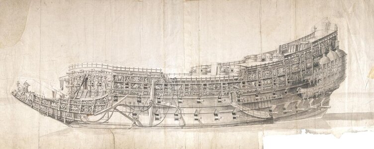
The build is at the stage now where though has to be given to the features visible on the weather deck, halfdeck, and forecastle. I'm looking for advice from members out there who have some knowledge of the typical ladder layouts of early 17th century English ships for access to the upper deck of the forecastle. Perhaps some of you know of another example of an English ship from that time period which can be used as a reference, because we know nothing about the aft bulkhead of the forecastle on HMS Sovereign of the Seas. Given this ship was unique, but I'd rather copy a known style of some feature than make a blind guess. It is very important that the feature copied be from approximately the same time period as the ship.
Later in the 17th century, ladders such as these were popular in the style used by John McKay in his interpretation of the ship. McKay solves the problem of interference with the gun carriages by bridging over them. This leave little room for those gun crews. There are known ladders similar to these from the poop down to the halfdeck on this ship. The ladder just aft of the forecastle seems out of place also, providing a problem of securing the lower decks against boarders, and is superfluous since there is at least one other ladder leading down from the waist. I do like the frequent use of cavals and kevels McKay used on the bulwarks, since belaying pins were not known to be used on ships at the time of the Sovereign with the frequency that they are in later ships. The Wasa has some belaying pins, but not many.
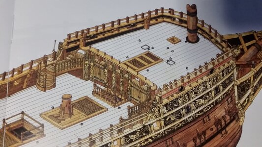
The Seppings model likewise has ladders leading up to the forecastle, similar to those I installed on La Couronne.
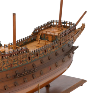
Here is ADVBiker's Sovereign build. This seems the most logical layout with regard to access to the forecastle, since this ship is meant to be a fortress against boarding. There is only one access to the upper forecastle, that being a single door, and no ladders from the weather deck. And interior ladder from the weather deck to the upper forecastle is already featured on my model. It seems counterintuitive to have access ladders right next to sakers (lighter, 6 pound guns) meant to shower the waist in shot if boarded. The upper forecastle would easily be overrun by marines.
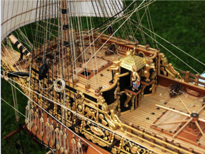
The model at US Naval Academy in Annapolis, Maryland shows no ladders to the weather deck, and even shows most of the spar deck gratings in place over the waist.
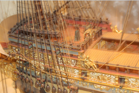
Wolfgang Rotter's famous scratch built model likewise has no ladders. It's hard to make guesses based on the results of other's research, because we don't know what their sources were, or if they had any information regarding this feature. Mistakes as well as features are often copied from one model maker to another, and we usually never know where an idea came from. All this has to be taken into consideration when deciding the features on your model if you are striving for accuracy.
So, please, if you have any examples that could serve as a guide, speak up and help a fellow builder out.
Later in the 17th century, ladders such as these were popular in the style used by John McKay in his interpretation of the ship. McKay solves the problem of interference with the gun carriages by bridging over them. This leave little room for those gun crews. There are known ladders similar to these from the poop down to the halfdeck on this ship. The ladder just aft of the forecastle seems out of place also, providing a problem of securing the lower decks against boarders, and is superfluous since there is at least one other ladder leading down from the waist. I do like the frequent use of cavals and kevels McKay used on the bulwarks, since belaying pins were not known to be used on ships at the time of the Sovereign with the frequency that they are in later ships. The Wasa has some belaying pins, but not many.

The Seppings model likewise has ladders leading up to the forecastle, similar to those I installed on La Couronne.

Here is ADVBiker's Sovereign build. This seems the most logical layout with regard to access to the forecastle, since this ship is meant to be a fortress against boarding. There is only one access to the upper forecastle, that being a single door, and no ladders from the weather deck. And interior ladder from the weather deck to the upper forecastle is already featured on my model. It seems counterintuitive to have access ladders right next to sakers (lighter, 6 pound guns) meant to shower the waist in shot if boarded. The upper forecastle would easily be overrun by marines.

The model at US Naval Academy in Annapolis, Maryland shows no ladders to the weather deck, and even shows most of the spar deck gratings in place over the waist.

Wolfgang Rotter's famous scratch built model likewise has no ladders. It's hard to make guesses based on the results of other's research, because we don't know what their sources were, or if they had any information regarding this feature. Mistakes as well as features are often copied from one model maker to another, and we usually never know where an idea came from. All this has to be taken into consideration when deciding the features on your model if you are striving for accuracy.

So, please, if you have any examples that could serve as a guide, speak up and help a fellow builder out.

Last edited:
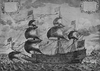
Whether or not to 1) place the spar deck gratings in place, 2) leave them all off but show ledges where they are supported on the forecastle and halfdeck bulkheads and other support points, or 3) show some of the gratings but not all of them like the Annapolis model is something I have yet to decide upon. The Annapolis model seems the most accurate with regard to the spar deck construction.The annapolis model look with the gratings is certainly one to consider as this is also the layout you see on the John Payne etsching and also on the van de velde drawing. If these gratings were present in war time then the stair would have been elsewhere.
View attachment 320034
View attachment 320035
Full spar decks on the waist and halfdeck would show the ship as it originally would have seen combat in the first years of its life before the first refit, but make it impossible to see any deck details. Something to ponder on. Perhaps using some miniature figures lifting spars and grates into place and assembling the spar decks with the help of the garnet tackles over the waist is an option.
Last edited:
Good morning Kurt- all above my Pay grade however awesome to read and learn both the intricacies of these ships and how think out a plan going forward. Cheers GrantWhether or not to 1) place the spar deck gratings in place, 2) leave them all off but show ledges where they are supported on the forecastle and quarterdeck bulkheads and other support points, or 3) show some of the gratings but not all of them like the Annapolis model is something I have yet to decide upon. The Annapolis model seems the most accurate with regard to the spar deck construction.
Full spar decks on the waist and quarterdeck would show the ship as it originally would have seen combat in the first years of its life before the first refit, but make it impossible to see any deck details. Something to ponder on. Perhaps using some miniature figures lifting spars and grates into place and assembling the spar decks with the help of the garnet tackles over the waist is an option.
Personally I have my doubts, if a ship like the Sovereign of the Seas from the first half of 17th century had gratings over the weather deck, especially not so heavy wooden gratings.
Usually they had nets to get a protection against bording and falling sails and yards during action - the small wlakway or any other cover came as I know later.
but I found this 17th-century hand-coloured engraving by John Payne of The Sovereign of the Seas, showing seamen at this area standing or walking ?????
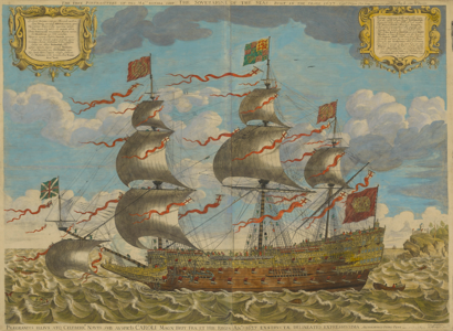
Sorry, but realized just now, that it is the same Maarten showed already in black and white

John McKay was already mentioned
In Hendrik Busmans book about the ornaments is this sketch shown
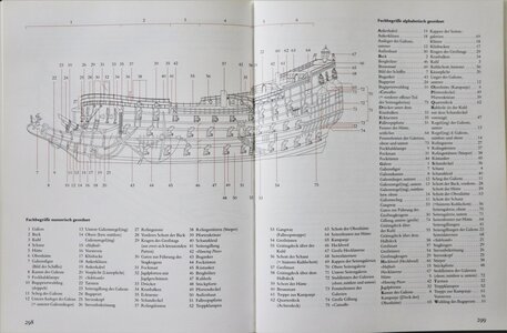
No.55 says "Grätingsdeck über der Kuhl" translated like "deck of gratings over the waist"
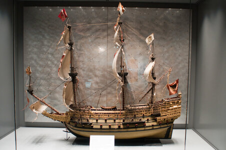
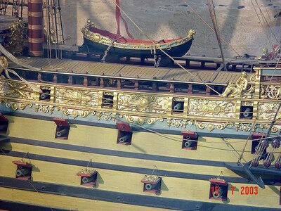
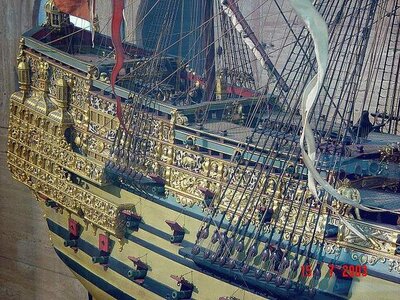
Here some photos showing the model of the Kriegstein collection - in exhibition in the USNA - United States Naval Academy Museum in Anapolis, Maryland
The model was built between 1918 and 1920, by Henry Culver and Paul Chalfin. So it is not a contemporary model.
Usually they had nets to get a protection against bording and falling sails and yards during action - the small wlakway or any other cover came as I know later.
but I found this 17th-century hand-coloured engraving by John Payne of The Sovereign of the Seas, showing seamen at this area standing or walking ?????

Sorry, but realized just now, that it is the same Maarten showed already in black and white

John McKay was already mentioned
Book review - Sovereign of the Seas 1637-John McKay
Sovereign of the Seas by John McKay 1637 Part 1 Hardcover:296 Pages Publisher:Seaforth Publishing 3rd March 2020 Language:English ISBN-10:1526766299 ISBN-13:978-1526766299 DIMENSIONS:254x295x25mm RRP:£40 SYNOPSIS Sovereign of the Seas was probably the most lavishly decorated warship ever...
shipsofscale.com
In Hendrik Busmans book about the ornaments is this sketch shown

No.55 says "Grätingsdeck über der Kuhl" translated like "deck of gratings over the waist"
Book review - Book Review: "SOVEREIGN OF THE SEAS - Die Skulpturen des britischen Königsschiffes von 1637" by Hendrik Busmann
Book Review: SOVEREIGN OF THE SEAS - Die Skulpturen des britischen Königsschiffes von 1637 by Hendrik Busmann Gebundene Ausgabe: 311 Seiten Verlag: CONVENT Hamburg (2002) Sprache: Deutsch ISBN-10: 3934613195 ISBN-13: 978-3934613195 Verpackungsabmessungen: 27,4 x 21,5 x 3 cm / 1.580...
shipsofscale.com
Here some photos showing the model of the Kriegstein collection - in exhibition in the USNA - United States Naval Academy Museum in Anapolis, Maryland
The model was built between 1918 and 1920, by Henry Culver and Paul Chalfin. So it is not a contemporary model.


