HMS Sovereign of the Seas - Bashing DeAgostini Beyond Believable Boundaries

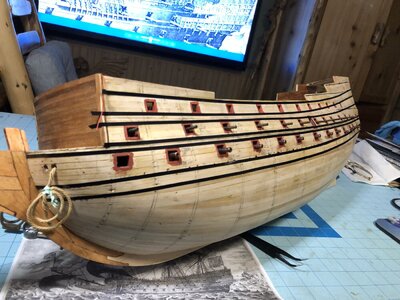
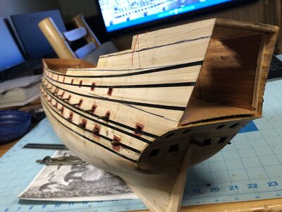
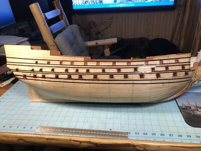
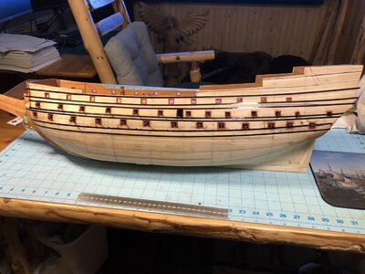
After some careful planning and measurement, the wales were marked on the hull with pinstripe tape. The wales will be in three widths, as shown in Payne's engraving, which was used as the primary source for locating the wales. The key points of reference were the gun ports. Estimates for where the wales go were made relative to those. It was difficult to reconcile the spacing of the wales on Payne's engraving with the DeAgostini hull shape because the distance in height between the lower and middle gun ports was quite narrow, almost too much to fit two wales between them.
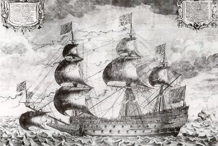
Payne's engraving cca 1640 BEST SOURCE FOR RIGGING.jpg

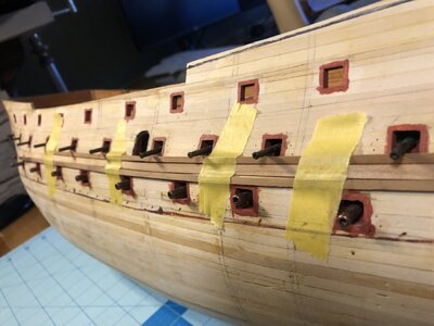
Strips of wood were test fit to see how they appeared with regard to size in relation to Payne's engraving. These wales are a little too wide. These 3.25mm wales could be used for the bottom pair, then 3mm for the pair above the lower guns, and 2.5mm used for those above that. I'm going to use cherry wood because it is obtainable in strips locally, and the color is not too dark or too light.
1083 Test Fitting Wale Strips.JPG

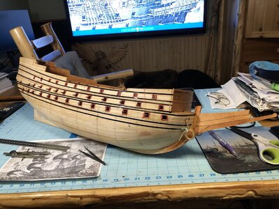
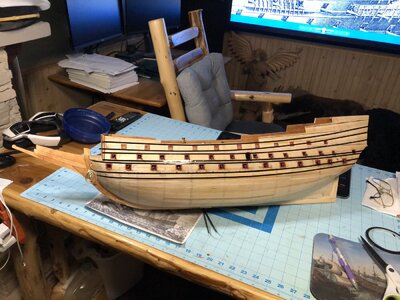
1/8" pinstripe tape was used to lay out the location of the wales. including the thinner ones above and below the upper gun deck ports, which will be gold. Careful adjustment of the tape was made using a tweezers to pull small sections of tape off the hull to reposition them in order to eliminate waves and flat spots in the overall curves of each wale. The lines of the wales overall should flow as parallel with each other in curves that diverge in width gently as you move aft. It appears that I may have to adjust the lower two wales upward near the curve of the bow a tiny bit, but that would cause them to form a shallow peak as they approach the keel when viewed at the bow. Right now they are parallel with the waterline at the bow. What do you guys think?
1084 Mark Wales With Pinstripe Tape.JPG

1085 Mark Wales With Pinstripe Tape.JPG

1086 Mark Wales With Pinstripe Tape.JPG

1087 Mark Wales With Pinstripe Tape.JPG
 
After some careful planning and measurement, the wales were marked on the hull with pinstripe tape. The wales will be in three widths, as shown in Payne's engraving, which was used as the primary source for locating the wales. The key points of reference were the gun ports. Estimates for where the wales go were made relative to those. It was difficult to reconcile the spacing of the wales on Payne's engraving with the DeAgostini hull shape because the distance in height between the lower and middle gun ports was quite narrow, almost too much to fit two wales between them.

View attachment 327240

Strips of wood were test fit to see how they appeared with regard to size in relation to Payne's engraving. These wales are a little too wide. These 3.25mm wales could be used for the bottom pair, then 3mm for the pair above the lower guns, and 2.5mm used for those above that. I'm going to use cherry wood because it is obtainable in strips locally, and the color is not too dark or too light.
View attachment 327241

1/8" pinstripe tape was used to lay out the location of the wales. including the thinner ones above and below the upper gun deck ports, which will be gold. Careful adjustment of the tape was made using a tweezers to pull small sections of tape off the hull to reposition them in order to eliminate waves and flat spots in the overall curves of each wale. The lines of the wales overall should flow as parallel with each other in curves that diverge in width gently as you move aft. It appears that I may have to adjust the lower two wales upward near the curve of the bow a tiny bit, but that would cause them to form a shallow peak as they approach the keel when viewed at the bow. Right now they are parallel with the waterline at the bow. What do you guys think?
View attachment 327242

View attachment 327243

View attachment 327244

View attachment 327245
It’s hard to keep the wales from having flat spots. Are you planning on scarfing them or will you make them one continuous piece of wood? The aft portion Loks a little wide between them. Maybe that’s just the perspective.
 
It’s hard to keep the wales from having flat spots. Are you planning on scarfing them or will you make them one continuous piece of wood? The aft portion Loks a little wide between them. Maybe that’s just the perspective.
The pinstripes are pretty well curved. I am thinking on making false scarf lines with a chisel shaped knife blade since the wales are only about 3mm in width, and such joints may create slight bend points and discontinuities of the overall curve if not carefully installed. The widening spacing at the aft is the natural extension of the lines under the side galleries, and most of that will not be visible, since the galleries cover that portion of the hull. I tried to keep the wale lines opening in an even fan as they expand in distance between each other at the stern. However, it was noted that on Payne's engraving, the wales are curved in distinct pairs at the bottom and a triple set at the top which frames the decorations.
 
Hi Kurt

I spent months pondering this.IMHO the upper Wales do not curve upwards to that extent and sweep upwards all to the same extent which flows into the gallery design.

This is not easy as the kit design has the relationship between decks all wrong.

My best advice is that you mock up the side gallery using card and try against the model before proceeding, the horizontal borders of decor on the side galleries need to sweep up with the same angle of sheer as the Wales to look correct, something that Sergal didn't quite get right.

If pictures of my model may help, just let me know and I will take some

Kind Regards

Nigel
Thanks Nigel! I will proceed as you recommend and start work on designing the gallery structure, then adjust the wales. Please send me any photos you can take of your model as a guide. I have been using your hull and Uwe's alongside the historical sources to answer most of my questions up to this point. All your help is much appreciated!
 
Thanks Nigel! I will proceed as you recommend and start work on designing the gallery structure, then adjust the wales. Please send me any photos you can take of your model as a guide. I have been using your hull and Uwe's alongside the historical sources to answer most of my questions up to this point. All your help is much appreciated!

Kurt I will get my model down from the loft this evening and take some pics and try and get some square on to the model so you can compare.Thumbsup
 
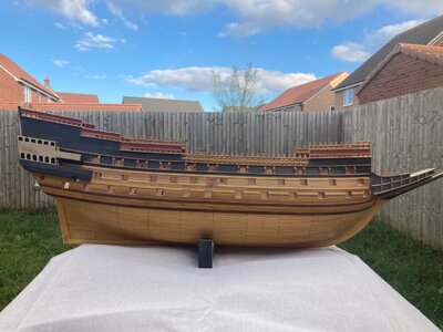
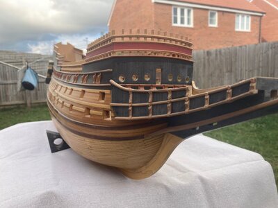
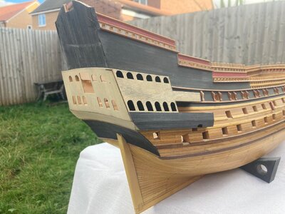
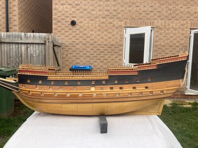
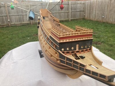
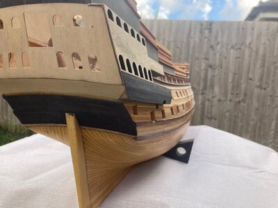
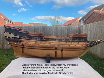
Here you go then guys, can't believe I had hundreds of pics of getting to this stage then lost them all through various reasons:rolleyes:

Sun has come out now so took these outside:)

Kurt,one side has the gallery fitted, one does not, so hope you can see what I mean about the sheer of the Wales tying in with that of the gallery.

This was the best compromise I could achieve given how close the lower and middle deck were.

IMG_0518.jpgIMG_0519.jpgIMG_0520.jpgIMG_0521.jpgIMG_0522.jpgIMG_0523.jpg
 
Here you go then guys, can't believe I had hundreds of pics of getting to this stage then lost them all through various reasons:rolleyes:

Sun has come out now so took these outside:)

Kurt,one side has the gallery fitted, one does not, so hope you can see what I mean about the sheer of the Wales tying in with that of the gallery.

This was the best compromise I could achieve given how close the lower and middle deck were.

View attachment 327293View attachment 327294View attachment 327295View attachment 327296View attachment 327297View attachment 327298
Thanks Nigel! I saved all these photos for reference in your build log folder on my hard drive along with all the others. They have been invaluable to me. I see where you placed your wales, and how they flow into the lines of the gallery. I will adjust my wales accordingly.
 
Last edited:
Sounds like a good plan. Are you doing hinges for your gun port covers? If so, will they fit with the wales' positions?
I haven't decided for using working hinges from Corel like I did on La Couronne or fixed, false hinges that do not work. I am leaning toward the latter because the hinges won't look overly large. I'm trying to focus on keeping more features in scale on this model, especially in things that weren't done that way on the last model. Things that are typically over sized on models typically include gun port hinges, gun tackle blocks, rigging line diameters, running rigging blocks, cannon barrels, trenails, and other details. This is especially true for kits. The wales as marked with the pinstripe tape are far away enough from the gun ports to allow installation of open gun port lids. Although the tape appears to run over the top edges of the ports which would interfere with the lid hinges, that will be adjusted as required when installing the wale strips. It's a construction point I am aware of, but thanks for watching out for me by mentioning it, Vic! Another thing to watch for is any interferences between the gun port lids and the channels that will be mounted on the wales.
 
I haven't decided for using working hinges from Corel like I did on La Couronne or fixed, false hinges that do not work. I am leaning toward the latter because the hinges won't look overly large. I'm trying to focus on keeping more features in scale on this model, especially in things that weren't done that way on the last model. Things that are typically over sized on models typically include gun port hinges, gun tackle blocks, rigging line diameters, running rigging blocks, cannon barrels, trenails, and other details. This is especially true for kits. The wales as marked with the pinstripe tape are far away enough from the gun ports to allow installation of open gun port lids. Although the tape appears to run over the top edges of the ports which would interfere with the lid hinges, that will be adjusted as required when installing the wale strips. It's a construction point I am aware of, but thanks for watching out for me by mentioning it, Vic! Another thing to watch for is any interferences between the gun port lids and the channels that will be mounted on the wales.
I get it. On my last ship, I only used working hinges on the ones that would show, like the aft ports that were closed. I’m enjoying your build, by the way. Learning as I go from experience and watching others work.
 
Here you go then guys, can't believe I had hundreds of pics of getting to this stage then lost them all through various reasons:rolleyes:

Sun has come out now so took these outside:)

Kurt,one side has the gallery fitted, one does not, so hope you can see what I mean about the sheer of the Wales tying in with that of the gallery.

This was the best compromise I could achieve given how close the lower and middle deck were.

View attachment 327293View attachment 327294View attachment 327295View attachment 327296View attachment 327297View attachment 327298

IMG_0518.jpg
 

Hi Frank

If you look at Payne's artwork shown in Kurt's earlier post, this shows breaks not only in the lower of the two middle rails, but also breaks in the upper of the main wales.I know my breaks are not in the same place, the forward two are not present, but the aft two are.I couldn't replicate exactly as the middle and lower ports are too close together.These breaks in the Wales in Payne's work is also shown in the artwork of the same ship by Willem Van de Velds the elder, which was my main reference.

I understand what you are saying but there has been period artwork and models that demonstrate this rule not to be consistent.

Kind Regards

Nigel
 
Hi Frank

If you look at Payne's artwork shown in Kurts earlier post, this shows breaks not only in the lower of the two middle rails, but also breaks in the upper of the main wale.I know my breaks are not in the same place, the forward two are not present, but the aft two are.I couldn't replicate exactly as the middle and lower ports are too close together.

I understand what you are saying but there has been period artwork and models that demonstrate this rule not to be consistent.

Kind Regards

Nigel
Thank you for answering me, good job
 
Back
Top