HMS Sovereign of the Seas - Bashing DeAgostini Beyond Believable Boundaries

When you study the build of Dutch ships, you will learn that not the Wales are the main part of the structure but the keel and the "zeeg" (english I think seepage) of the ship together with the hull.
Only these types of ships
Steef66, are you referring to Me?
 
Steef66, are you referring to Me?
Yes I quoted your post and question. And gave the reason why the Wales are cut for the gunports. On ships like the Victory, the wales are a important part of the structure. These types of ships, galleons like a dutch 2 decker have a different structure where the keel is the most important part of the structure.
 
Yes I quoted your post and question. And gave the reason why the Wales are cut for the gunports. On ships like the Victory, the wales are a important part of the structure. These types of ships, galleons like a dutch 2 decker have a different structure where the keel is the most important part of the structure.
I'm sorry but I don't agree with what you say, I don't look at paintings to study naval architecture but texts of the time
 
Hi Frank

If you look at Payne's artwork shown in Kurt's earlier post, this shows breaks not only in the lower of the two middle rails, but also breaks in the upper of the main wales.I know my breaks are not in the same place, the forward two are not present, but the aft two are.I couldn't replicate exactly as the middle and lower ports are too close together.These breaks in the Wales in Payne's work is also shown in the artwork of the same ship by Willem Van de Velds the elder, which was my main reference.

I understand what you are saying but there has been period artwork and models that demonstrate this rule not to be consistent.

Kind Regards

Nigel
To add to what Nigel said, the differences in where he made breaks in the wales due to the gun ports are different from Payne's engraving on his model. The reason for this is because of the hull shape and deck positions in the DeAgostini model being different from the ship depicted in Payne's engraving. It it hard to get all the features on the DeAgostini hull lined up with those in the engraving. The wales are interrupted by gun ports because the lines formed but the wales do not follow the lines of the deck where they meet the hull. The two cross, creating discontinuities in the wales. Those sections of the wales which are removed from the hull are replaced on the gun port lids to keep the appearance of uninterrupted wales. The wales help hold the frames in position while the skeleton of the hull is being constructed, but are less important for structural strength after the planking layers are added and all the frames are in place. All of the parts contribute to the strength of the hull, but having occasional breaks in the wales is not a serious weakness in the completed hull. On early great ships such as these, the keel and frames are very strong, and the wales less important than later ships, as framing became different in structure and lighter. As a general trend, this resulted in ships that could carry more load from guns and sail faster. Remember that great ships of the 1620's and 1630's are prototypes in large ocean going vessels, built larger than ever before, and were refined and simplified over the next two centuries. HMS Sovereign of the Seas was considered obsolete in the 1690's and spent most of it's later career at anchor and neglected in maintenance.
 
I'm sorry but I don't agree with what you say, I don't look at paintings to study naval architecture but texts of the time
Then you should study the old Dutch texts and archives. I can't remember in which book I read it, it may well have been a book by Ab Hoving. But the curvature of the decks on these ships, together with the specially composed keel, frames and hull plamking (inner and outside), form the supporting force in the hull. The hull timbers did not contribute to this type of ship.otherwise they would not be able to be sawn through.
It was also not a rigid structure in this type of ship. The keel could sag considerably in the middle during heavy waves.
If you read in the books of v. Ijk and Witsen how the hull was built, it also differs from the conventional construction of ships.
Only 100% sure that the SOS is built according to the Dutch construction method, but looking at the model of the hull it comes very close. That's why I don't find it strange that the wales are interrupted.
 
To add to what Nigel said, the differences in where he made breaks in the wales due to the gun ports are different from Payne's engraving on his model. The reason for this is because of the hull shape and deck positions in the DeAgostini model being different from the ship depicted in Payne's engraving. It it hard to get all the features on the DeAgostini hull lined up with those in the engraving. The wales are interrupted by gun ports because the lines formed but the wales do not follow the lines of the deck where they meet the hull. The two cross, creating discontinuities in the wales. Those sections of the wales which are removed from the hull are replaced on the gun port lids to keep the appearance of uninterrupted wales. The wales help hold the frames in position while the skeleton of the hull is being constructed, but are less important for structural strength after the planking layers are added and all the frames are in place. All of the parts contribute to the strength of the hull, but having occasional breaks in the wales is not a serious weakness in the completed hull. On early great ships such as these, the keel and frames are very strong, and the wales less important than later ships, as framing became different in structure and lighter. As a general trend, this resulted in ships that could carry more load from guns and sail faster. Remember that great ships of the 1620's and 1630's are prototypes in large ocean going vessels, built larger than ever before, and were refined and simplified over the next two centuries. HMS Sovereign of the Seas was considered obsolete in the 1690's and spent most of it's later career at anchor and neglected in maintenance.
Sorry Kurt and Steef, I asked a simple question and Nigel kindly replied, why are you making these comments to me? Maybe I bothered, if that's what I apologize and take away the trouble
 
Sorry Kurt and Steef, I asked a simple question and Nigel kindly replied, why are you making these comments to me? Maybe I bothered, if that's what I apologize and take away the trouble
Sorry Frank. It appears I replied to the wrong person, and this whole conservation was not directed only at yourself. I replied for everyone's benefit. Please don't ever be afraid to ask us questions or make comments. It is certainly no bother, and when people make comments or ask questions, I learn a lot! We are very informal and enjoy discussing these topics. Thanks!
 
Last edited:
You don't have to apologise. You ask something and Kurt and I give you an answer. Why the wales may have been interrupted. Because according to the format of your question that would not be possible. We explain that it is and why. But if you don't agree with that answer, then that's fine. Or as Kurt also says.
 
Then you should study the old Dutch texts and archives. I can't remember in which book I read it, it may well have been a book by Ab Hoving. But the curvature of the decks on these ships, together with the specially composed keel, frames and hull plamking (inner and outside), form the supporting force in the hull. The hull timbers did not contribute to this type of ship.otherwise they would not be able to be sawn through.
It was also not a rigid structure in this type of ship. The keel could sag considerably in the middle during heavy waves.
If you read in the books of v. Ijk and Witsen how the hull was built, it also differs from the conventional construction of ships.
Only 100% sure that the SOS is built according to the Dutch construction method, but looking at the model of the hull it comes very close. That's why I don't find it strange that the wales are interrupted.
is this the book you mentioned?

AEL OLDE
And
CONTEMPORARY
SHIP-BUILDING
\
AND
boss:
Waer in whitloopigh wert traded the way
van Scheeps-timmeren, by Greeks and Romey-
nen: Naval Exercises , Combat * Discipline, Punishment , Laws and Customs,
benejfens
Equal magnitudes of Ships on time, decompose
in all its parts : Verfchil of building tuffchen foreign and our landaerc : Indifch Vaertuygh : Galey-bouvv : present-day Ship-duties: Verrijckt with a reex verrijckt Zee-mans fpreeck-words and names.
Usually decorated with many Buy Plates.
Written by
NICOLAES WITSEN
 
Nicolaes Witsens scheeps-bouw-konst open gestelt

 
Last edited:
Agreed. Much better. Whenever I see wales that don't track with the planking I get a twitch (yes, I know this is a first planking but still...).
I twitch when the wales don’t follow the cannon openings and haphazardly go through them. Very odd! I suppose they are like this, on this particular ship, but it certainly is not pleasing to the eye. It’s like nailing your door frame out of line with the door! It will never look correct, even if it was historically done that way, at least from a carpentry and artistic point of view that is. That alone would make me chose a different ship. But I still appreciate the attraction people have to this ship, even if I don’t share it.
 
Wales are curved, decks much less so. Yes, it appears strange to our mechanical modern minds. It was the form of the day, and it appealed to the shipbuilders of the time.

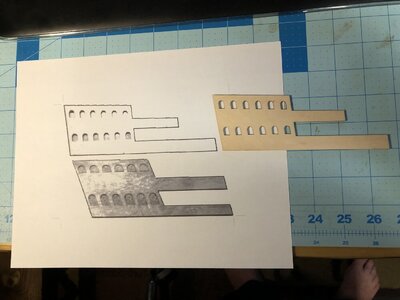
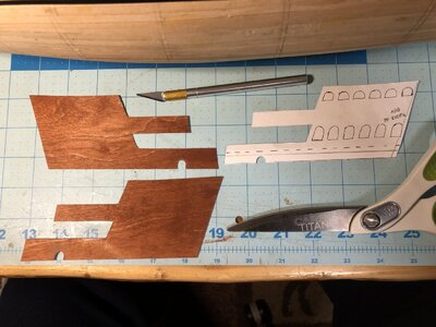
Today the outer most side of the side gallery was based on a photo provided by Nigel, who did all the homework redesigning the DeAgostini model to more closely match Payne's and Willem van deWelde's depictions of the ship. After manupulating the image in Gimp software, I was able to print a 1:1 scale image that matched the size of the DeAgostini side gallery piece, and thereby had a very close pattern which Nigel used on his ship. After a few minor adjustments of the shape to properly align and fit the hull on my model, the pattern was used to make two 0.5mm plywood gallery pieces.

After only three printings on the printer, I got the pattern size perfect.
1090 Use Nigel's Gallery Pattern (Below).JPG

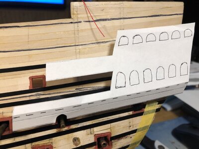
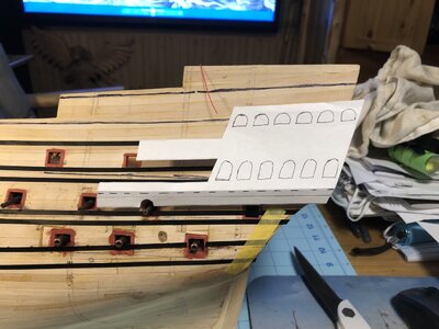
Adding the bottom strip to Nigel's pattern, and folding a seam along the dashed line, the proper shape of the gallery was formed.
1091 Test Paper Pattern.JPG


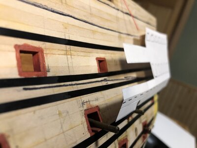
1092 Establish Angle.JPG

Looks pretty close so far.
1093 Test Fit Pattern.JPG


1094 Test Fit Pattern.JPG

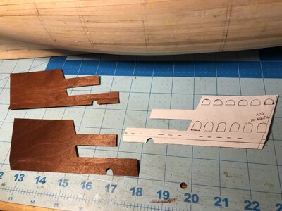
The pattern was transferred to 0.5mm three-fly birch plywood which previously stained and used for the false decks.
1095 Cut Pattern in Thin Plywood.JPG

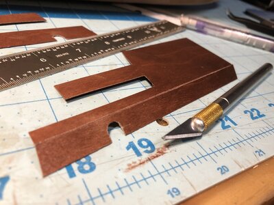
Cutting partially through the wood, the wood was folded, and the seam was reinforced by filling the cut with PVA glue.
1096 Scribe Line and Reinforce Fold Line with Glue.JPG


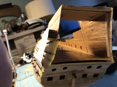
1097 Parts Adjusted to Fit.JPG

Next, the other pieces will be made from thicker sheets of wood, all scratch built to complete the side galleries. The windows will also be cut out, after checking to make sure their positions will align with the interior decks that will be installed later.
1098 Tets Fit.JPG
 
I twitch when the wales don’t follow the cannon openings and haphazardly go through them. Very odd! I suppose they are like this, on this particular ship, but it certainly is not pleasing to the eye. It’s like nailing your door frame out of line with the door! It will never look correct, even if it was historically done that way, at least from a carpentry and artistic point of view that is. That alone would make me chose a different ship. But I still appreciate the attraction people have to this ship, even if I don’t share it.
Sorry Frank. It appears I replied to the wrong person, and this whole conservation was not directed only at yourself. I replied for everyone's benefit. Please don't ever be afraid to ask us questions or make comments. It is certainly no bother, and when people make comments or ask questions, I learn a lot! We are very informal and enjoy discussing these topics. Thanks!
Good morning to you, just to be consistent with my research, Nigel's model has nothing to cite, here is a text from Duhamel du Monceau's text "
Pregnant 15.


The pregnant 15, are sometimes improperly called the "forms". They are large boards that are wider and once thicker than the others. Since they behave like belts all around the vessel at different heights, they serve to chain it, and form protrusions that give it grace.

The pieces of the pregnant women are connected to each other by means of sculls, and fixed to the ribs by means of nails, and directly to the armrests and to the porches, by means of the pins of these same pieces that are inserted inside on washers.

There are usually two pregnant women under each battery. Later we will indicate the way to trace them. It will be enough, for the moment, to say that it is necessary to avoid, as far as possible, that they are cut by the hatches, and that the second pregnant must be conducted in such a way as to pass through the last rear hatch that cuts it a little. It continues along the entire length and under the doors of the first battery up to the front, where it ends a little below the last front door. The other pregnant women, who are placed above, follow the same curvature as this one.

Now I would like to go into a little detail on the width and thickness of pregnant women, because it is necessary to know their dimensions to make a plan well.

The pregnant women of the first battery are nearly as wide as the keel, and their thickness is 5 lines, 9 points (13 mm) for every inch (27.1 mm) of their width.

The third pregnant is 1/7 less wide than the second, and its thickness is 5 lines, 9 points (13 mm) for every inch (27.1 mm) of its width.

The fourth is 1/12 less thick than the third, and its thickness is 5 lines, 8 points (12.8 mm) for each inch (27.1 mm) of its width.

The pregnant fifth has a width of 2/3 of the first, and its thickness is 5 lines 8 points (12.8 mm) for each inch (27.1 mm) of its width.

The discolati, or girdles of the gang leader, have, as a width, 2/3 of the width of the first pregnant. Their thickness is 5 lines, 8 points (12.8 / 27.1mm) for each inch (27.1mm) of their width.

The pregnant of the outline of the mainmast and the foremast have a width of 6 lines, 6 points (14.7 mm) for each inch (27.1 mm) of the width of the first pregnant, and their thickness is 5 lines, 8 points (12.8 mm) for each inch (27.1 mm) of their width.

The pregnant of the second posterior contour has a width of 5 lines, 8 points (12.8 mm) for each inch (27.1 mm) of the width of the first pregnant, and its thickness is 5 lines, 6 points (12, 4 mm) for each inch (27.1 mm) of its width.

The pregnant of the third posterior contour has a width of 5 lines, 6 points (12.4 mm) for each inch (27.1 mm) of the width of the first pregnant, and its thickness is 5 lines, 6 points (12, 4 mm) for each inch (27.1 mm) of its width.
 
Good morning to you, just to be consistent with my research, Nigel's model has nothing to cite, here is a text from Duhamel du Monceau's text "
Pregnant 15.


The pregnant 15, are sometimes improperly called the "forms". They are large boards that are wider and once thicker than the others. Since they behave like belts all around the vessel at different heights, they serve to chain it, and form protrusions that give it grace.

The pieces of the pregnant women are connected to each other by means of sculls, and fixed to the ribs by means of nails, and directly to the armrests and to the porches, by means of the pins of these same pieces that are inserted inside on washers.

There are usually two pregnant women under each battery. Later we will indicate the way to trace them. It will be enough, for the moment, to say that it is necessary to avoid, as far as possible, that they are cut by the hatches, and that the second pregnant must be conducted in such a way as to pass through the last rear hatch that cuts it a little. It continues along the entire length and under the doors of the first battery up to the front, where it ends a little below the last front door. The other pregnant women, who are placed above, follow the same curvature as this one.

Now I would like to go into a little detail on the width and thickness of pregnant women, because it is necessary to know their dimensions to make a plan well.

The pregnant women of the first battery are nearly as wide as the keel, and their thickness is 5 lines, 9 points (13 mm) for every inch (27.1 mm) of their width.

The third pregnant is 1/7 less wide than the second, and its thickness is 5 lines, 9 points (13 mm) for every inch (27.1 mm) of its width.

The fourth is 1/12 less thick than the third, and its thickness is 5 lines, 8 points (12.8 mm) for each inch (27.1 mm) of its width.

The pregnant fifth has a width of 2/3 of the first, and its thickness is 5 lines 8 points (12.8 mm) for each inch (27.1 mm) of its width.

The discolati, or girdles of the gang leader, have, as a width, 2/3 of the width of the first pregnant. Their thickness is 5 lines, 8 points (12.8 / 27.1mm) for each inch (27.1mm) of their width.

The pregnant of the outline of the mainmast and the foremast have a width of 6 lines, 6 points (14.7 mm) for each inch (27.1 mm) of the width of the first pregnant, and their thickness is 5 lines, 8 points (12.8 mm) for each inch (27.1 mm) of their width.

The pregnant of the second posterior contour has a width of 5 lines, 8 points (12.8 mm) for each inch (27.1 mm) of the width of the first pregnant, and its thickness is 5 lines, 6 points (12, 4 mm) for each inch (27.1 mm) of its width.

The pregnant of the third posterior contour has a width of 5 lines, 6 points (12.4 mm) for each inch (27.1 mm) of the width of the first pregnant, and its thickness is 5 lines, 6 points (12, 4 mm) for each inch (27.1 mm) of its width.
Thank you Frank! I will use those dimensions to determine the width and thickness of the wales. This is a lot better than just making guesses based on Payne's engraving. You can see that the pair of wales change width as you go from the keel to the gunwale. According to these calculations, the sizes of the wales will be as follows, starting at the bottom:

Width of Keel: 4.78mm
First and Second Wales, below lower battery: width 4.78mm, thickness 2.29mm (my guess was 4mm wide)
Third Wale, above the lower battery: width 4.09mm, thickness 1.96mm (my guess was 3.5mm wide)
Fourth Wale, below the middle battery: width 3.74mm, thickness 1.77mm (my guess was 3.5mm wide)
Fifth (and sixth) Wales, above the middle battery: width 3.18mm, thickness 1.50mm (my guess was 3mm wide)

The rest of your measurements did not translate well from Italian into English, so you may have to use pictures to describe what a discolati is, and what the posterior contours are. I can not understand what those parts are.

My guesses for the widths of the wales were fairly close, which isn't bad since I estimated them by comparing them to the height of an open gun port. I haven't attempted to estimate the thickness of the wales, and now I won't have to.

Thank you for the useful information on wales, Frank! That was very helpful.
the text i said from boudriot is the bible of french architecture but, the concept is of construction and that, if you are interested let me know
 
Great work Kurt, glad the pics proved useful.This is where you find you may need to increase the height of the hull at the stern,I did

One thing I did was to print the Lely portrait out and then copy it at a percentage so the width of the transom match my model.I could then use this as a point of reference.Note the distance and viewpoint of the artist is such that it is almost a true view on the sloping transom.

Regarding the Wale debate, L'Ambiteux is shown with Wales broken by the aft ports on the lower two decks in the Monograph by Ancre.
I was planning on doing the same study using Lely's portrait of Peter Pett. I already have it printed in paper. Despite the flaws in the painting regarding the location of the tiller and the round tuck, the proportions of the layout of the decorations are pretty close to the model. The width and shape of the profile of the side galleries as viewed from the stern will be determined from Lely. I did notice that the stern needs to be raised just a bit, mostly to increase the angle of the poop deck gunwale. That adjustment is getting closer.

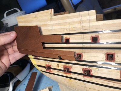
I was able to maneuver the wales to mimic most of the locations were they are broken by gun ports to match Payne's engraving. The height between the lower and middle batteries is quite compressed due to the DeAgostini hull design. It's too late to move the lower gun deck down a few millimeters. Wait.. I have a saw here . . .
 
Back
Top