Stunning Kurt. I’m with Vic. Hiking and I don’t go together too well. That looks like a really tough climb- satisfaction when you summit! Beautiful photos. Cheers Grant
-

Win a Free Custom Engraved Brass Coin!!!
As a way to introduce our brass coins to the community, we will raffle off a free coin during the month of August. Follow link ABOVE for instructions for entering.
-

PRE-ORDER SHIPS IN SCALE TODAY!
The beloved Ships in Scale Magazine is back and charting a new course for 2026!
Discover new skills, new techniques, and new inspirations in every issue.
NOTE THAT OUR FIRST ISSUE WILL BE JAN/FEB 2026
You are using an out of date browser. It may not display this or other websites correctly.
You should upgrade or use an alternative browser.
You should upgrade or use an alternative browser.
HMS Sovereign of the Seas - Bashing DeAgostini Beyond Believable Boundaries
- Thread starter DARIVS ARCHITECTVS
- Start date
- Watchers 105
Hello Kurt unique view and a great untouched nature, enjoy your vacation.
- Joined
- Sep 3, 2021
- Messages
- 5,199
- Points
- 738

Way out of my comfort zone, being afraid of heights...No work on the ship recently because it was time to take vacation, so a friend and I drove to Wyoming and hiked/climbed Medicine Bow Peak in the Snowy Mountains. It was 12,006' at the top and the last half mile was climbing over huge rocks and boulders. We parked the truck at Gap Lakes Trailhead and started hiking. The hike was the hardest we have ever done, but I didn't need any oxygen, so my recovery from Covid appears to be complete. The weather was perfect. From where we were staying in Hot Springs, South Dakota, we drove 4.5 hours, hiked up and down the peak, then drove back. Long day!
View attachment 324514
Starting point east of Sugarloaf Mountain looking west
View attachment 324513
Me at the summit
View attachment 324515
The last half mile of rocks we had to climb over to get there
View attachment 324516
The reason for going there - look at that view! That's Sugarloaf Mountain to the east.
View attachment 324517
My hiking buddy Matt resting at the top.
View attachment 324518
I'd say that's enough adventure for a while. Back to work... gotta cut hardwood for the stem and keel...
Nonetheless, breathtaking views.
Beautiful scenery! In one of your photo's someone is blocking the view!!
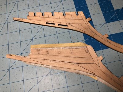
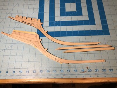
FINALLY some progress! I replicated the stem and part of the keel in maple wood today. Many of the parts in the assembly were individually cut and fit, but some of the scarf joints are just scribed with a razor knife and filled with pencil graphite, and you can't see much of a difference. I did not make the cuts for the gammoning yet, and the cuts for the beakhead supports will not be made, but were just marked for reference. There is a small step in the kee to accept the false keel. I will use vertical scarf joints for the rest of the keel, being simulated again with knife cuts to keep it strong.


- Joined
- Jan 21, 2022
- Messages
- 891
- Points
- 403

Thank you. You're my saviour. I don't have time and skill for making them as individual parts, this is just an excellent solutionsome of the scarf joints are just scribed with a razor knife and filled with pencil graphite, and you can't see much of a difference
Awesome Kurt! But does it fit the ship?
Because I wanted the timbers’ grains to go in different directions, I covered the keel, stem, and stern with strips of walnut veneer. Each had its own grain direction which would be important for strength on a real ship. I don’t know if that would make it too thick on your model, Kurt.
I'm working on that part. It's very close, but not quite seamless... YET. The trough that it fits in between the edges of the planks requires careful filing to wide it first. I started on that, but the fitting is not there yet. I want to drill many 1mm holes through the keel into the plywood false keel and insert brass wire to serve as pins for reinforcement, since the model will be places into a keel vice later, and the heavy weight of the hull with all that extra wood inside could help snap off the keel if bumped. The ends of the pins will be covered by the false keel strip later on.Awesome Kurt! But does it fit the ship?
Last edited:
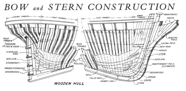
Using veneers how I did the stem on my last model, and it looks fine. At that time I didn't know all the parts of a stem, like the stempost, stemson (internal), keelson (internal), apron (internal), and gripe, which are typical parts of the stem assembly on 18th century English ships. Internal parts are not represented on my model and not visible externally anyway. (Even I have limits). I don't have any examples of early 17th century stem timber arrangements, and it is known that most of them for all ships were unique, with only a few styles common in the 18th and 19th centuries, from what I can gather from my limited sources. Basically, the stem on my ship was a near copy of another modeler's style. The basic parts are there, the stem, and gripe, and the parts of the beakhead support attached to them.Because I wanted the timbers’ grains to go in different directions, I covered the keel, stem, and stern with strips of walnut veneer. Each had its own grain direction which would be important for strength on a real ship. I don’t know if that would make it too thick on your model, Kurt.
Example from a 19th century clipper ship
Last edited:
In a vain attempt distract everyone from DocKattner's thread, more work was performed on the keel of the Sovereign. The rest of the keel parts were cut from hard maple. The false keel they will be joined to needed to be filed straight, and space between the plank edges on either side needed to be files to widen the gap, and the keel parts now fit with a press fit. Scarf joints were cut by eye using the desktop bandsaw, then parts filed and sanded to fit by hand. I'm not a CNC machine, but they fit well enough, plus the keel will be painted greyish white anyhow, so the wood grain and joints will be hidden anyway. I just wanted some scarf practice because it's fun. All the parts are test fitted but not yet secured to the hull.
Since my beloved Samsung Galaxy 5 Sport cell phone went through the wash machine last week, I have to use an iPhone to take pictures. The pictures are a tad better, but using that phone to transfer files is a pain.
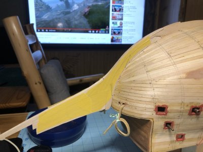
Masking tape holds the loose stem parts together.
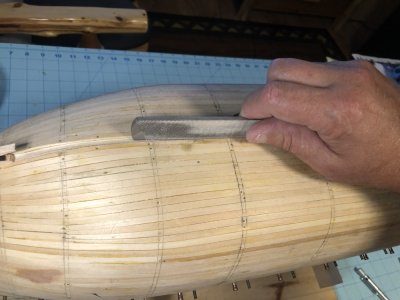
The edge of this file did a good job evening the false heel and widening the slot into which the keel will fit.
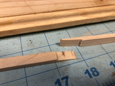
Scarf joints are rough cut by eye using a bandsaw, then filed to fit.
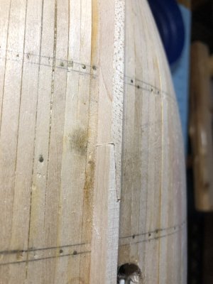
The forward keel scarf joint behind the stem assembly.
The deadwood nearest the keel needed thinning and shaping to get it close to the width of the keel.
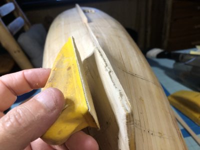
I'm glad the keel actually came out straight.
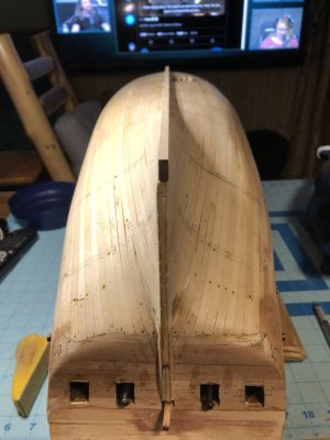
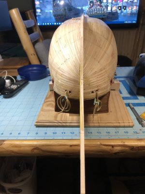
The keel looks good. The sternpost is next.
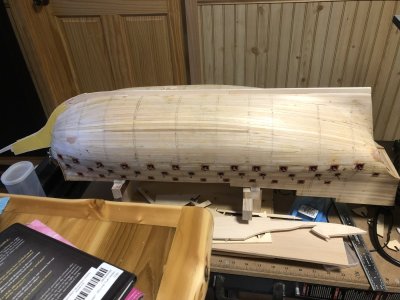
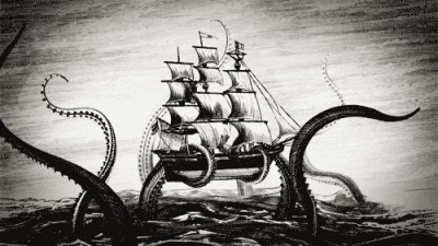
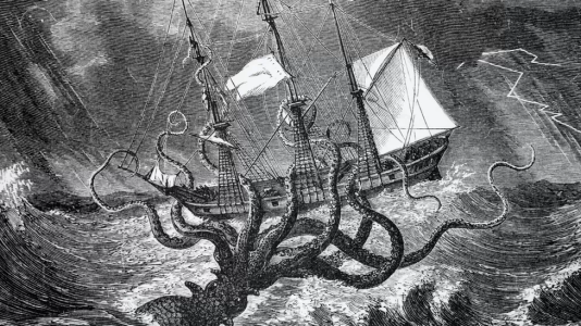
And here's a gratuitous kraken attack...
Since my beloved Samsung Galaxy 5 Sport cell phone went through the wash machine last week, I have to use an iPhone to take pictures. The pictures are a tad better, but using that phone to transfer files is a pain.
Masking tape holds the loose stem parts together.

The edge of this file did a good job evening the false heel and widening the slot into which the keel will fit.

Scarf joints are rough cut by eye using a bandsaw, then filed to fit.

The forward keel scarf joint behind the stem assembly.

The deadwood nearest the keel needed thinning and shaping to get it close to the width of the keel.

I'm glad the keel actually came out straight.


The keel looks good. The sternpost is next.

And here's a gratuitous kraken attack...

Knew the Kraken would feature somewhere Kurt 
Are you planing on doweling the stem to the hull ?

Are you planing on doweling the stem to the hull ?
You’re kraken me up, man!(Somebody had to say it.). I’ve never done one with a false keel like that. Good workmanship, Kurt.
Unlike my previous model, this one makes the keel separate from the false keel. No really good reason, and it would have been far stronger with an integral keel.You’re kraken me up, man!(Somebody had to say it.). I’ve never done one with a false keel like that. Good workmanship, Kurt.
I would tend to agree about the strength issue. I believe I’ve seen several instances of this kind of construction.Unlike my previous model, this one makes the keel separate from the false keel. No really good reason, and it would have been far stronger with an integral keel.
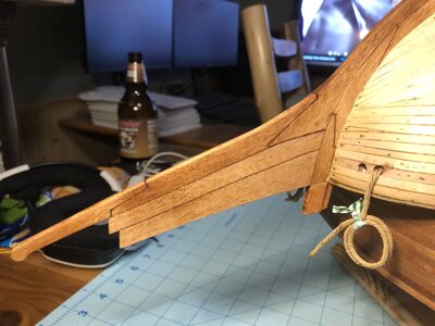
The stem and keel assembly was glued together and installed on the hull. Areas that will not be painted later were stained with gunstock color (red brown) Minwax stain and then oiled with Danish Oil.
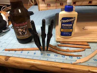
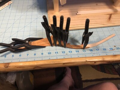
Began gluing the stem parts together.
Pins were made from 1.05mm brass wire.
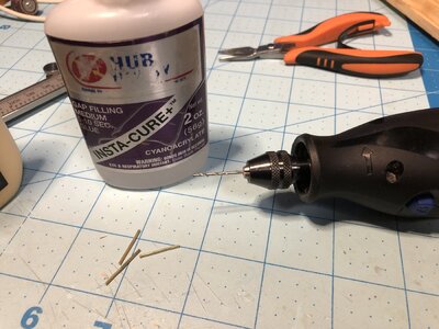
Several holes were drilled though the hard maple keel and into the plywood beneath. CA glue was used to glue all the pins in place. All the pin ends will be beneath the false keel so they won't be visible.
The stem assembly was glued to the bow, and the keel segments were glued to the hull all the way to the sternpost.
The false keel was cut from maple and glued to the keel. Masking tape holds the strip in place until it dries.
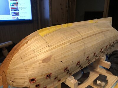
View of the keel assembly from the stern. The electronics in the hull will be covered over with final planking, leaving only the plug hole and the switch paddle exposed later in the build.
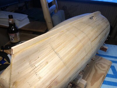
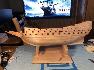
Progress so far. When the keel is dry and solid, the model can be held in a multi-positioning keel vise which will help greatly when working on the topmost decks and rigging.
Began gluing the stem parts together.


Pins were made from 1.05mm brass wire.

Several holes were drilled though the hard maple keel and into the plywood beneath. CA glue was used to glue all the pins in place. All the pin ends will be beneath the false keel so they won't be visible.

The stem assembly was glued to the bow, and the keel segments were glued to the hull all the way to the sternpost.

The false keel was cut from maple and glued to the keel. Masking tape holds the strip in place until it dries.

View of the keel assembly from the stern. The electronics in the hull will be covered over with final planking, leaving only the plug hole and the switch paddle exposed later in the build.

Progress so far. When the keel is dry and solid, the model can be held in a multi-positioning keel vise which will help greatly when working on the topmost decks and rigging.

That stem looks great Kurt. 
Good morning Kurt. Great posts and the stem work is kraken good....you startedThe stem and keel assembly was glued together and installed on the hull. Areas that will not be painted later were stained with gunstock color (red brown) Minwax stain and then oiled with Danish Oil.
Began gluing the stem parts together.
View attachment 325883
View attachment 325884
Pins were made from 1.05mm brass wire.
View attachment 325885
Several holes were drilled though the hard maple keel and into the plywood beneath. CA glue was used to glue all the pins in place. All the pin ends will be beneath the false keel so they won't be visible.
View attachment 325886
The stem assembly was glued to the bow, and the keel segments were glued to the hull all the way to the sternpost.
View attachment 325887
The false keel was cut from maple and glued to the keel. Masking tape holds the strip in place until it dries.
View attachment 325888
View of the keel assembly from the stern. The electronics in the hull will be covered over with final planking, leaving only the plug hole and the switch paddle exposed later in the build.
View attachment 325889
Progress so far. When the keel is dry and solid, the model can be held in a multi-positioning keel vise which will help greatly when working on the topmost decks and rigging.
View attachment 325890
 The scarf joint and the “faux” one are awesome. Cheers Grant
Well, I made a small mistake on the keel. It's supposed to extend rearward to the end of the sternpost, and it was cut too short. Oops.Good morning Kurt. Great posts and the stem work is kraken good....you startedThe scarf joint and the “faux” one are awesome. Cheers Grant
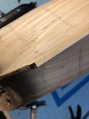
 I made an extension with maple wood and, with any luck, the paint will fully hide the seam. The plywood center frame of the model at the stern protrudes too far back, and needs to be trimmed to make room for the sternpost. I will have to carefully cut off 3mm along transom using a coping saw and sand the area to make it as straight as possible, then attach the sternpost. The fix should turn out okay.


