Good afternoon. Wow you are building a marvellous Victory. One of the best builds of a Caldercraft kit I have seen. I also love the way you have presented your log for us. Kudos and Bravo. Cheers Grant
-

Win a Free Custom Engraved Brass Coin!!!
As a way to introduce our brass coins to the community, we will raffle off a free coin during the month of August. Follow link ABOVE for instructions for entering.
-

PRE-ORDER SHIPS IN SCALE TODAY!
The beloved Ships in Scale Magazine is back and charting a new course for 2026!
Discover new skills, new techniques, and new inspirations in every issue.
NOTE THAT OUR FIRST ISSUE WILL BE JAN/FEB 2026
You are using an out of date browser. It may not display this or other websites correctly.
You should upgrade or use an alternative browser.
You should upgrade or use an alternative browser.
HMS Victory of Caldercraft by Wil
- Thread starter Scheepshoorn
- Start date
- Watchers 27
-
- Tags
- caldercraft victory
- Joined
- Oct 15, 2017
- Messages
- 1,190
- Points
- 443

Great work! I appreciate your approach to the construction and implementation of the different elements. I did have this kit, but decided to go in another direction and sold it to a SoS member. Had I kept it, I'd be happy to have achieved the results you are currently realizing.
- Joined
- Jul 17, 2024
- Messages
- 75
- Points
- 113

11 The upper canon deck planking
In between lining the gun ports, I also tackled the upper gun deck. As this cannot be fitted into the hull in its entirety, I cut the lower deck in the middle and taped it at the bottom, making it hinged.
As mentioned, in this and the next decks, I plan to apply the waterway principle.
In brief, I will tell you how I worked out this process
First applied a strip of millimetre paper and copied the curve of the inner ramp, which I had marked earlier. Later used this template to copy the waterway in four sections onto a strip of the same wood as the deck planks, 1mm thick. I believe this is Tanganyika wood. I made this strip (the waterway) 2x the width of the deck planks, so 8mm in this case.

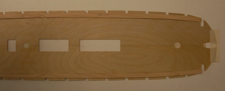
Then, exactly in the middle, the king plank was fitted. By the way, this is only half glued to one of the two deck boards, so that the hinge function is maintained. On the outside against the watercourse, some strips glued to maintain the plank's fit

Then the planking of the straight planks. In my case, these are 95mm, as applied to the middle gun deck. The bandage used here too is the four-plank system.
Once all the whole planks are in place, the "joggling" can begin. The planks then end 1/3 of their width in the waterway. The distance of the course should be at least 1.5 - 2 times the plank width. In turn mark off plank, sand at an angle and mark off waterway plank with this. When all parts fit dry, glue on the last pieces and the waterway. With all that glue on your fingers it becomes a bit of a mess, but I had already gained some experience with this for the middle gun deck. For the caulking seams, I blacked out all planks on the sides with a carpenter's pencil.
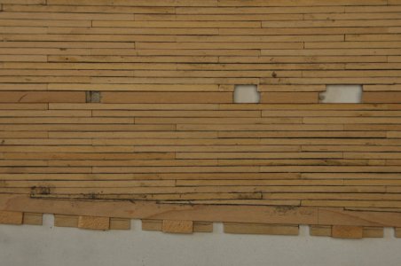
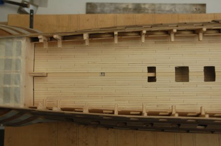
Afterwards, I briefly laid the deck in the hull and put on the inner bulwarks on the starboard and port sides. My intention is to put the inner bulwark of the upper gun deck on first, so I can finish the gun ports and the outer side of the hull here too . I can slide the upper gun deck under this later. But I also want to keep using my tilt construction for finishing the outside as long as possible.
This is still going to be a bit of a battle as to which phase comes first. Maybe I can even take the auxiliary structure up to the upper gun deck. This we will see.
In between lining the gun ports, I also tackled the upper gun deck. As this cannot be fitted into the hull in its entirety, I cut the lower deck in the middle and taped it at the bottom, making it hinged.
As mentioned, in this and the next decks, I plan to apply the waterway principle.
In brief, I will tell you how I worked out this process
First applied a strip of millimetre paper and copied the curve of the inner ramp, which I had marked earlier. Later used this template to copy the waterway in four sections onto a strip of the same wood as the deck planks, 1mm thick. I believe this is Tanganyika wood. I made this strip (the waterway) 2x the width of the deck planks, so 8mm in this case.


Then, exactly in the middle, the king plank was fitted. By the way, this is only half glued to one of the two deck boards, so that the hinge function is maintained. On the outside against the watercourse, some strips glued to maintain the plank's fit

Then the planking of the straight planks. In my case, these are 95mm, as applied to the middle gun deck. The bandage used here too is the four-plank system.
Once all the whole planks are in place, the "joggling" can begin. The planks then end 1/3 of their width in the waterway. The distance of the course should be at least 1.5 - 2 times the plank width. In turn mark off plank, sand at an angle and mark off waterway plank with this. When all parts fit dry, glue on the last pieces and the waterway. With all that glue on your fingers it becomes a bit of a mess, but I had already gained some experience with this for the middle gun deck. For the caulking seams, I blacked out all planks on the sides with a carpenter's pencil.

- Once everything has hardened, sand and scrape the whole thing thoroughly. And ready is Wil.
- I find the result acceptable, so for the first time. What I do wonder is whether going to 1/3 of the plank width over a shorter distance would not be nicer. Perhaps this is another option for the next decks.

Afterwards, I briefly laid the deck in the hull and put on the inner bulwarks on the starboard and port sides. My intention is to put the inner bulwark of the upper gun deck on first, so I can finish the gun ports and the outer side of the hull here too . I can slide the upper gun deck under this later. But I also want to keep using my tilt construction for finishing the outside as long as possible.
This is still going to be a bit of a battle as to which phase comes first. Maybe I can even take the auxiliary structure up to the upper gun deck. This we will see.
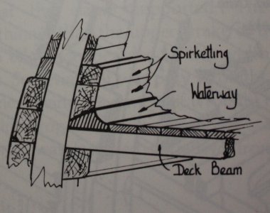
From David Steel's The Elements and Practice of Naval Architecture 1805, the breadth of the upper gun deck waterway was 11" on a first rate. At a scale of 1:72 this would be 3.9mm. If it were an older ship built to the Establishments starting in 1719 the waterways were specified as being 1 inch wider than the deck planking.I made this strip (the waterway) 2x the width of the deck planks, so 8mm in this case.
Couple pics below that you may find helpful. I have no idea what shape the waterway was on Victory after her rebuild in 1803, but the dimension of 11" should be very close. The first drawing is described as 18th century from Goodwin's The Construction and Fitting of the English Man of War. The second is 19th century practice.

- Joined
- Jul 17, 2024
- Messages
- 75
- Points
- 113

12 In between to Portsmouth
For my 70th birthday, my wife gifted me a holiday trip to southern England, with the main destination, of course, being the Historical Dockyard in Portsmouth. A visit I had been looking forward to for some time.
When we arrived in Portsmouth, our first impression was "What a huge and beautiful complex"
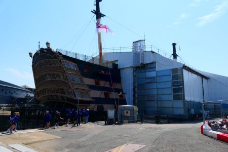
But what a huge setback. The Victory lay there as if it had just come out of a heavy sea battle and had barely been sunk. All masts had been removed and there was a huge tent covering almost the entire ship, with huge scaffolding structures inside. Only the tip of the bow and the galleries and a few gun ports protruded from this tent.
Once inside the tent, I found that much of the hull planking had disappeared. I had imagined I would be able to take lots of photos of the exterior, given the stage my project was in at the time.
My wife and I were only there for a few hours that afternoon, so we made a quick tour of the ship to get our bearings. Inside, everything seems to be intact and there is still a bit of everything on the upper decks. Bending down is often the motto here. Would the crew have worn construction helmets in the past?
All in all, at the moment, a serious setback.
We went back the following two days. We still managed to score a lot of great photos here and there. I had so hoped to find a lot of support from this during my project. It's no different.
On the other hand, when it will soon be completely finished, it will certainly be worth going back again. I'm afraid my Victory will be up and running by then.


Ahh what a disappointment. I supposed you could probably see more of the internal structures but a let down non the less. I guess another hope across the channel is in order once they have finished renovating her. Cheers Grant12 In between to Portsmouth
For my 70th birthday, my wife gifted me a holiday trip to southern England, with the main destination, of course, being the Historical Dockyard in Portsmouth. A visit I had been looking forward to for some time.
When we arrived in Portsmouth, our first impression was "What a huge and beautiful complex"
But what a huge setback. The Victory lay there as if it had just come out of a heavy sea battle and had barely been sunk. All masts had been removed and there was a huge tent covering almost the entire ship, with huge scaffolding structures inside. Only the tip of the bow and the galleries and a few gun ports protruded from this tent.
Once inside the tent, I found that much of the hull planking had disappeared. I had imagined I would be able to take lots of photos of the exterior, given the stage my project was in at the time.
My wife and I were only there for a few hours that afternoon, so we made a quick tour of the ship to get our bearings. Inside, everything seems to be intact and there is still a bit of everything on the upper decks. Bending down is often the motto here. Would the crew have worn construction helmets in the past?
All in all, at the moment, a serious setback.
We went back the following two days. We still managed to score a lot of great photos here and there. I had so hoped to find a lot of support from this during my project. It's no different.
On the other hand, when it will soon be completely finished, it will certainly be worth going back again. I'm afraid my Victory will be up and running by then.
View attachment 505100
View attachment 505101
- Joined
- Jul 17, 2024
- Messages
- 75
- Points
- 113

13 Painting
With a lot of filing, cutting and sanding, I got rid of the biggest unevennesses. The exterior steps are also complete on both sides of the ship, although I still think the top step sits a bit low. I may have to add another step, that way the step won't be so big. I will see this when I have fitted the top deck.
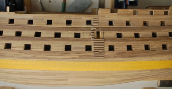
In the bare woodwork, this all looks reasonable, but as soon as you start painting, the real unevennesses show up. Because yellow has such an incredibly poor covering effect, I decided to go a bit overboard with the primers. A bit too much yellow, you will say, but that is the intention in this case. Later painting in ochre yellow will then be easier. This also applies to the black colour, which will probably cover in one go.
Let this first primer cure very well first and only then sand and touch up all unevenness before the second primer, is my idea.

After applying the first primer, it appeared that the seams between the gunwales had become slightly disproportionate, looking at the gun port rebates.
Under the motto "tackle problems right away and don't postpone until later "I had to make concessions to myself right away by promising to build the ship without putty. Unfortunately, this did not quite work out.

After a second coat of primer, the result had already improved a lot, if I do say so myself. What I was not yet satisfied with was the finish of the gun ports. In particular, the rebates were not all the same yet. I also made a first attempt to paint the gun ports in a different colour, which did not disappoint with a small brush for the rebates.

The main discussion, with which we travelled to England, was the final "yellow colour". Well in Portsmouth we didn't become much wiser about that, except to say that lots of colours are good.
Then to work with the colours, which Caldercraft supplied with the kit. It is a paint kit from Admirality Paints, which according to the supplier should contain the "real" colours. You already taste it, the ochre yellow colour supplied does differ a lot from what we have seen in England and from the many photos that can be consulted here and there.
As I had indicated, I first primed the hull a few times to get a covering result with paint that was too yellow. This allowed me to put a final touch on the quality of the various seams, especially in the wales.
Then the ochre yellow on top. Again, a few thin coats. In the photo below, these are the darker strips.
This colour, to my mind, deviates too much from what it once was and I didn't like it either. So mixing further. Eventually it should become like the lighter strips in the photo. These have now been painted twice and don't quite cover them yet either, so the exact rendering will be slightly different. The advantage of this yellow paint is that you only have to mark the boundary with the black once. You keep seeing these lines, which I will have to focus on later with the masking tape for the black colour.

For painting and copper plating, I would still like to use my tilt attachment so that I can rotate the hull in all positions. After that, it should be upright and the work on the decks can begin.
After the primers, the main focus of the paint job was to apply the yellow and black stripes to the hull. After thoroughly studying many photos and estimating distances from the gun ports, this is the result.
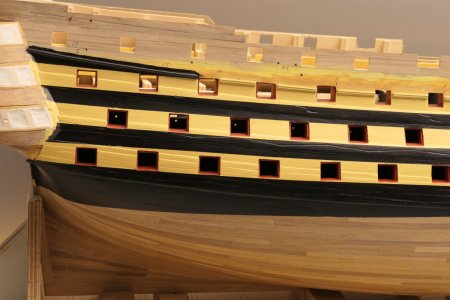
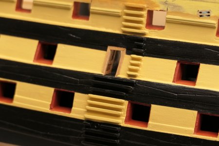
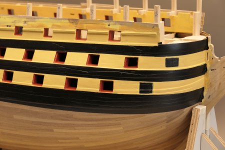
I also painted the gun ports red on the inside. Here I ran into a contradiction between the build description and the photos of the Victory in reality. The build description indicates that the gun ports should be the colour of the exterior paintwork, yellow or black in other words, while the photos show that the gun ports are red. I have stuck to the latter observation.
On the starboard side, the section below the waterline will not be coppered. I have now treated this section twice with matt varnish, also including the black up to the lower gunwale on a trial basis. This gave such a nice and calm result from the paintwork that I decided to also varnish the yellow and black of the hull above.
While painting and counting before assembling the hatches, I also discovered that I had not fitted one gun port. This turned out not to be cut out in the plywood strip of the first planking. Anyway, we fixed that too. So it keeps surprising every now and then.

With a lot of filing, cutting and sanding, I got rid of the biggest unevennesses. The exterior steps are also complete on both sides of the ship, although I still think the top step sits a bit low. I may have to add another step, that way the step won't be so big. I will see this when I have fitted the top deck.

In the bare woodwork, this all looks reasonable, but as soon as you start painting, the real unevennesses show up. Because yellow has such an incredibly poor covering effect, I decided to go a bit overboard with the primers. A bit too much yellow, you will say, but that is the intention in this case. Later painting in ochre yellow will then be easier. This also applies to the black colour, which will probably cover in one go.
Let this first primer cure very well first and only then sand and touch up all unevenness before the second primer, is my idea.

After applying the first primer, it appeared that the seams between the gunwales had become slightly disproportionate, looking at the gun port rebates.
Under the motto "tackle problems right away and don't postpone until later "I had to make concessions to myself right away by promising to build the ship without putty. Unfortunately, this did not quite work out.

After a second coat of primer, the result had already improved a lot, if I do say so myself. What I was not yet satisfied with was the finish of the gun ports. In particular, the rebates were not all the same yet. I also made a first attempt to paint the gun ports in a different colour, which did not disappoint with a small brush for the rebates.

The main discussion, with which we travelled to England, was the final "yellow colour". Well in Portsmouth we didn't become much wiser about that, except to say that lots of colours are good.
Then to work with the colours, which Caldercraft supplied with the kit. It is a paint kit from Admirality Paints, which according to the supplier should contain the "real" colours. You already taste it, the ochre yellow colour supplied does differ a lot from what we have seen in England and from the many photos that can be consulted here and there.
As I had indicated, I first primed the hull a few times to get a covering result with paint that was too yellow. This allowed me to put a final touch on the quality of the various seams, especially in the wales.
Then the ochre yellow on top. Again, a few thin coats. In the photo below, these are the darker strips.
This colour, to my mind, deviates too much from what it once was and I didn't like it either. So mixing further. Eventually it should become like the lighter strips in the photo. These have now been painted twice and don't quite cover them yet either, so the exact rendering will be slightly different. The advantage of this yellow paint is that you only have to mark the boundary with the black once. You keep seeing these lines, which I will have to focus on later with the masking tape for the black colour.

For painting and copper plating, I would still like to use my tilt attachment so that I can rotate the hull in all positions. After that, it should be upright and the work on the decks can begin.
After the primers, the main focus of the paint job was to apply the yellow and black stripes to the hull. After thoroughly studying many photos and estimating distances from the gun ports, this is the result.


I also painted the gun ports red on the inside. Here I ran into a contradiction between the build description and the photos of the Victory in reality. The build description indicates that the gun ports should be the colour of the exterior paintwork, yellow or black in other words, while the photos show that the gun ports are red. I have stuck to the latter observation.
On the starboard side, the section below the waterline will not be coppered. I have now treated this section twice with matt varnish, also including the black up to the lower gunwale on a trial basis. This gave such a nice and calm result from the paintwork that I decided to also varnish the yellow and black of the hull above.
While painting and counting before assembling the hatches, I also discovered that I had not fitted one gun port. This turned out not to be cut out in the plywood strip of the first planking. Anyway, we fixed that too. So it keeps surprising every now and then.

- Joined
- Oct 17, 2020
- Messages
- 1,691
- Points
- 488

Hi Allan, but should the gun ports be of different sizes between one deck and another based on the calibration of the guns?FrankHi Wil,
I checked a number of additional contemporary plans, and based on those it appears the Caldercraft drawings are wrong. No matter, if you are happy, that is what a hobby is all about.
Allan
should the gun ports be of different sizes between one deck and another based on the calibration of the guns?
The gun port openings were different on each deck because the guns were different sizes on each deck. How this was determined is a great question. I have always relied on the scantlings in the contracts, contemporary drawings, the 1719, 1745, and 1750 Establishments, The Shipbuilder's Repository or Steel's The Elements and Practice of Naval Architecture depending on what is available and the era. As a result I never looked for information on how these dimensions were determined. Taking it further, when some ships had their armament changed to a different caliber, I wonder if the ports were re-sized?
NB: It is my understanding that contracts were only issued for ships built in private yards. and as first rates were built in HM yards no contracts were issued so the other sources mentioned above would be my fall back sources.
From a contract for a British 74, 1781.
Gun deck Port deep 2 feet 8 inches, fore & aft 3 feet 5 inches (From Steel he gives 2' 9" X 3' 5" - From the Shipbuilder's Repository it gives 2'9" X 3' 6" so there are sometimes small differences)
Upper deck Ports deep 2 feet 8 inches fore & aft 2 feet 10 inches
Quarter deck Ports deep 2 feet 5 inches, Fore and Aft 2 feet 8 inches
For a 100 gun ship gundeck ports are shown in Steel and the SR as follows:
Gundeck-deep 2'9" X 3' 5" fore and aft
Middle Deck-deep2' 9" X 3' 3"fore and aft
Upper Deck-deep 2'8" X 2' 11"fore and aft
QD -deep 2'9" X 2' 6"fore and aft
Hope this is helpful or at least not TOO boring.
Allan
- Joined
- Oct 17, 2020
- Messages
- 1,691
- Points
- 488

There should also be distances from the first gunboat from the bow and distances between them.FrankThe gun port openings were different on each deck because the guns were different sizes on each deck. How this was determined is a great question. I have always relied on the scantlings in the contracts, contemporary drawings, the 1719, 1745, and 1750 Establishments, The Shipbuilder's Repository or Steel's The Elements and Practice of Naval Architecture depending on what is available and the era. As a result I never looked for information on how these dimensions were determined. Taking it further, when some ships had their armament changed to a different caliber, I wonder if the ports were re-sized?
NB: It is my understanding that contracts were only issued for ships built in private yards. and as first rates were built in HM yards no contracts were issued so the other sources mentioned above would be my fall back sources.
From a contract for a British 74, 1781.
Gun deck Port deep 2 feet 8 inches, fore & aft 3 feet 5 inches (From Steel he gives 2' 9" X 3' 5" - From the Shipbuilder's Repository it gives 2'9" X 3' 6" so there are sometimes small differences)
Upper deck Ports deep 2 feet 8 inches fore & aft 2 feet 10 inches
Quarter deck Ports deep 2 feet 5 inches, Fore and Aft 2 feet 8 inches
For a 100 gun ship gundeck ports are shown in Steel and the SR as follows:
Gundeck-deep 2'9" X 3' 5" fore and aft
Middle Deck-deep2' 9" X 3' 3"fore and aft
Upper Deck-deep 2'8" X 2' 11"fore and aft
QD -deep 2'9" X 2' 6"fore and aft
Hope this is helpful or at least not TOO boring.
Allan
Excellent progress Will13 Painting
With a lot of filing, cutting and sanding, I got rid of the biggest unevennesses. The exterior steps are also complete on both sides of the ship, although I still think the top step sits a bit low. I may have to add another step, that way the step won't be so big. I will see this when I have fitted the top deck.
View attachment 508155
In the bare woodwork, this all looks reasonable, but as soon as you start painting, the real unevennesses show up. Because yellow has such an incredibly poor covering effect, I decided to go a bit overboard with the primers. A bit too much yellow, you will say, but that is the intention in this case. Later painting in ochre yellow will then be easier. This also applies to the black colour, which will probably cover in one go.
Let this first primer cure very well first and only then sand and touch up all unevenness before the second primer, is my idea.
View attachment 508156
After applying the first primer, it appeared that the seams between the gunwales had become slightly disproportionate, looking at the gun port rebates.
Under the motto "tackle problems right away and don't postpone until later "I had to make concessions to myself right away by promising to build the ship without putty. Unfortunately, this did not quite work out.
View attachment 508159
After a second coat of primer, the result had already improved a lot, if I do say so myself. What I was not yet satisfied with was the finish of the gun ports. In particular, the rebates were not all the same yet. I also made a first attempt to paint the gun ports in a different colour, which did not disappoint with a small brush for the rebates.
View attachment 508160
The main discussion, with which we travelled to England, was the final "yellow colour". Well in Portsmouth we didn't become much wiser about that, except to say that lots of colours are good.
Then to work with the colours, which Caldercraft supplied with the kit. It is a paint kit from Admirality Paints, which according to the supplier should contain the "real" colours. You already taste it, the ochre yellow colour supplied does differ a lot from what we have seen in England and from the many photos that can be consulted here and there.
As I had indicated, I first primed the hull a few times to get a covering result with paint that was too yellow. This allowed me to put a final touch on the quality of the various seams, especially in the wales.
Then the ochre yellow on top. Again, a few thin coats. In the photo below, these are the darker strips.
This colour, to my mind, deviates too much from what it once was and I didn't like it either. So mixing further. Eventually it should become like the lighter strips in the photo. These have now been painted twice and don't quite cover them yet either, so the exact rendering will be slightly different. The advantage of this yellow paint is that you only have to mark the boundary with the black once. You keep seeing these lines, which I will have to focus on later with the masking tape for the black colour.
View attachment 508161
For painting and copper plating, I would still like to use my tilt attachment so that I can rotate the hull in all positions. After that, it should be upright and the work on the decks can begin.
After the primers, the main focus of the paint job was to apply the yellow and black stripes to the hull. After thoroughly studying many photos and estimating distances from the gun ports, this is the result.
View attachment 508162
View attachment 508163
View attachment 508172
I also painted the gun ports red on the inside. Here I ran into a contradiction between the build description and the photos of the Victory in reality. The build description indicates that the gun ports should be the colour of the exterior paintwork, yellow or black in other words, while the photos show that the gun ports are red. I have stuck to the latter observation.
On the starboard side, the section below the waterline will not be coppered. I have now treated this section twice with matt varnish, also including the black up to the lower gunwale on a trial basis. This gave such a nice and calm result from the paintwork that I decided to also varnish the yellow and black of the hull above.
While painting and counting before assembling the hatches, I also discovered that I had not fitted one gun port. This turned out not to be cut out in the plywood strip of the first planking. Anyway, we fixed that too. So it keeps surprising every now and then.
View attachment 508173
Beautiful work.
Why did you choose not to copper the hull?
It seems far more complicated than just giving a distance between. The contracts go into great detail regarding the size of the ports and relation with the room and space as well as the various thicknesses of the futtocks for each deck level. The best/easiest thing I found is when they write:There should also be distances from the first gunboat from the bow and distances between them.Frank
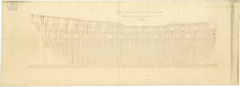
It being of the utmost consequence to the strength of the Ship that all the Timbers of the Frame should as much as possible be preserved from being cut by the Ports of each Deck. A Disposition for that purpose is made on the Draught, and as a further means to obtain it, the said Timbers appointed to make the sides of the Ports being continued up to the Top of the side are to be framed in bends.
Having the contemporary drawings gives the disposition. Unless the model is fully framed it is not so hard to use these drawings for both size and location and sheer line of the decks and ports. The profile drawing below is somewhat rare in that it shows a lot of the hull planking. The high resolution version can be found on the Wiki Commons site https://commons.wikimedia.org/wiki/Category:Ship_plans_of_the_Royal_Museums_Greenwich
Allan

Last edited:
Good afternoon Will. Wonderful progress. Cheers Grant13 Painting
With a lot of filing, cutting and sanding, I got rid of the biggest unevennesses. The exterior steps are also complete on both sides of the ship, although I still think the top step sits a bit low. I may have to add another step, that way the step won't be so big. I will see this when I have fitted the top deck.
View attachment 508155
In the bare woodwork, this all looks reasonable, but as soon as you start painting, the real unevennesses show up. Because yellow has such an incredibly poor covering effect, I decided to go a bit overboard with the primers. A bit too much yellow, you will say, but that is the intention in this case. Later painting in ochre yellow will then be easier. This also applies to the black colour, which will probably cover in one go.
Let this first primer cure very well first and only then sand and touch up all unevenness before the second primer, is my idea.
View attachment 508156
After applying the first primer, it appeared that the seams between the gunwales had become slightly disproportionate, looking at the gun port rebates.
Under the motto "tackle problems right away and don't postpone until later "I had to make concessions to myself right away by promising to build the ship without putty. Unfortunately, this did not quite work out.
View attachment 508159
After a second coat of primer, the result had already improved a lot, if I do say so myself. What I was not yet satisfied with was the finish of the gun ports. In particular, the rebates were not all the same yet. I also made a first attempt to paint the gun ports in a different colour, which did not disappoint with a small brush for the rebates.
View attachment 508160
The main discussion, with which we travelled to England, was the final "yellow colour". Well in Portsmouth we didn't become much wiser about that, except to say that lots of colours are good.
Then to work with the colours, which Caldercraft supplied with the kit. It is a paint kit from Admirality Paints, which according to the supplier should contain the "real" colours. You already taste it, the ochre yellow colour supplied does differ a lot from what we have seen in England and from the many photos that can be consulted here and there.
As I had indicated, I first primed the hull a few times to get a covering result with paint that was too yellow. This allowed me to put a final touch on the quality of the various seams, especially in the wales.
Then the ochre yellow on top. Again, a few thin coats. In the photo below, these are the darker strips.
This colour, to my mind, deviates too much from what it once was and I didn't like it either. So mixing further. Eventually it should become like the lighter strips in the photo. These have now been painted twice and don't quite cover them yet either, so the exact rendering will be slightly different. The advantage of this yellow paint is that you only have to mark the boundary with the black once. You keep seeing these lines, which I will have to focus on later with the masking tape for the black colour.
View attachment 508161
For painting and copper plating, I would still like to use my tilt attachment so that I can rotate the hull in all positions. After that, it should be upright and the work on the decks can begin.
After the primers, the main focus of the paint job was to apply the yellow and black stripes to the hull. After thoroughly studying many photos and estimating distances from the gun ports, this is the result.
View attachment 508162
View attachment 508163
View attachment 508172
I also painted the gun ports red on the inside. Here I ran into a contradiction between the build description and the photos of the Victory in reality. The build description indicates that the gun ports should be the colour of the exterior paintwork, yellow or black in other words, while the photos show that the gun ports are red. I have stuck to the latter observation.
On the starboard side, the section below the waterline will not be coppered. I have now treated this section twice with matt varnish, also including the black up to the lower gunwale on a trial basis. This gave such a nice and calm result from the paintwork that I decided to also varnish the yellow and black of the hull above.
While painting and counting before assembling the hatches, I also discovered that I had not fitted one gun port. This turned out not to be cut out in the plywood strip of the first planking. Anyway, we fixed that too. So it keeps surprising every now and then.
View attachment 508173
- Joined
- Jul 17, 2024
- Messages
- 75
- Points
- 113

Hello Gilbert,Excellent progress Will
Beautiful work.
Why did you choose not to copper the hull?
The 2e planking of the first side of the hull was so beautiful, that I dicided to maintain the look on this difficult job. The second side will be coppered.
Hi WillHello Gilbert,
The 2e planking of the first side of the hull was so beautiful, that I dicided to maintain the look on this difficult job. The second side will be coppered.
Indeed,good reason
- Joined
- Jul 17, 2024
- Messages
- 75
- Points
- 113

14 Upper gun deck equipment
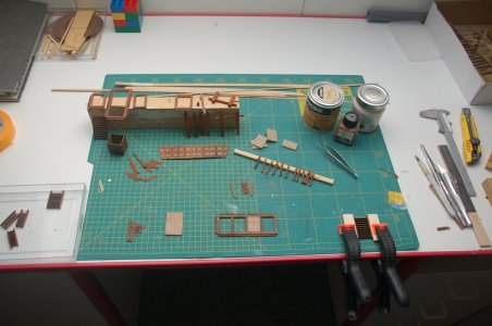
Making the various parts for the deck equipment could be done very nicely between the drying of the paintwork. It is nice and varied work, which you can use nicely as a stopping job.
Starting with the individual elements for the upper gun deck. I stained most of the elements twice with dark oak. After assembly, I then finished everything with matt clear varnish, sealing the last seams and masking the sheen of glue residue.
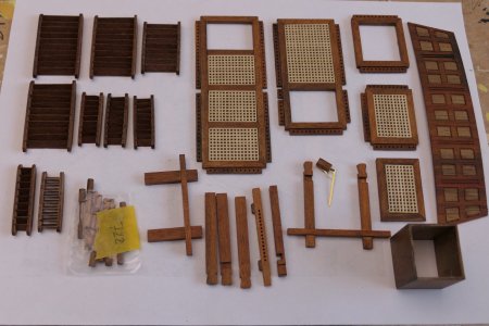

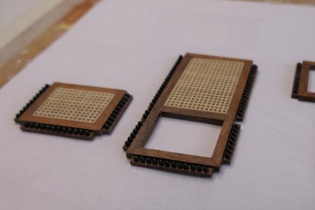
Once this deck was fitted, it could be assembled. I had also already applied the balls in the racks. I do this gluing work with clear varnish, which simplifies the work considerably. After all, you have more time to get things in place properly and you don't see anything of it after drying. I hate to think I would have had to do this with superglue. Once this glue job has hardened, a final check that all the balls are firmly in place and, if necessary, a small coat of clear varnish over the whole thing, and Wil is ready.
I also tackled the racks for the deadeys. The slings around the deadeys were fixed with some clear varnish before the cover strip could be mounted. Later the whole thing, including the deadeys and slings, has to be painted black. I haven't done this for now so that I can later turn the deadeyes in the right direction.

Meanwhile, the upper gun deck had also been fitted.
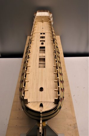
Good to see the effect of the wider king plank.
In my opinion, the watercourse planks are a bit too wide, they could be made a bit narrower on the upper decks, which will be fully visible later.
Below, on the middle canon deck, you can see the uprights of the railings for the stairs. The handrail is made of rope, which I have already attached and will be brought up in one piece later. The stairs will be mounted against these uprights.
The cleats have also been fixed, before I would forget them.
Making the various parts for the deck equipment could be done very nicely between the drying of the paintwork. It is nice and varied work, which you can use nicely as a stopping job.
Starting with the individual elements for the upper gun deck. I stained most of the elements twice with dark oak. After assembly, I then finished everything with matt clear varnish, sealing the last seams and masking the sheen of glue residue.


Once this deck was fitted, it could be assembled. I had also already applied the balls in the racks. I do this gluing work with clear varnish, which simplifies the work considerably. After all, you have more time to get things in place properly and you don't see anything of it after drying. I hate to think I would have had to do this with superglue. Once this glue job has hardened, a final check that all the balls are firmly in place and, if necessary, a small coat of clear varnish over the whole thing, and Wil is ready.
I also tackled the racks for the deadeys. The slings around the deadeys were fixed with some clear varnish before the cover strip could be mounted. Later the whole thing, including the deadeys and slings, has to be painted black. I haven't done this for now so that I can later turn the deadeyes in the right direction.

Meanwhile, the upper gun deck had also been fitted.

Good to see the effect of the wider king plank.
In my opinion, the watercourse planks are a bit too wide, they could be made a bit narrower on the upper decks, which will be fully visible later.
Below, on the middle canon deck, you can see the uprights of the railings for the stairs. The handrail is made of rope, which I have already attached and will be brought up in one piece later. The stairs will be mounted against these uprights.
The cleats have also been fixed, before I would forget them.
Good afternoon Wow some serious progress achieved- nice !!!! Your joinery is very neat - Kudos. Cheers Grant14 Upper gun deck equipment
Making the various parts for the deck equipment could be done very nicely between the drying of the paintwork. It is nice and varied work, which you can use nicely as a stopping job.
Starting with the individual elements for the upper gun deck. I stained most of the elements twice with dark oak. After assembly, I then finished everything with matt clear varnish, sealing the last seams and masking the sheen of glue residue.
View attachment 510312
View attachment 510313
View attachment 510314
View attachment 510315
Once this deck was fitted, it could be assembled. I had also already applied the balls in the racks. I do this gluing work with clear varnish, which simplifies the work considerably. After all, you have more time to get things in place properly and you don't see anything of it after drying. I hate to think I would have had to do this with superglue. Once this glue job has hardened, a final check that all the balls are firmly in place and, if necessary, a small coat of clear varnish over the whole thing, and Wil is ready.
I also tackled the racks for the deadeys. The slings around the deadeys were fixed with some clear varnish before the cover strip could be mounted. Later the whole thing, including the deadeys and slings, has to be painted black. I haven't done this for now so that I can later turn the deadeyes in the right direction.
View attachment 510316
Meanwhile, the upper gun deck had also been fitted.
View attachment 510317
Good to see the effect of the wider king plank.
In my opinion, the watercourse planks are a bit too wide, they could be made a bit narrower on the upper decks, which will be fully visible later.
Below, on the middle canon deck, you can see the uprights of the railings for the stairs. The handrail is made of rope, which I have already attached and will be brought up in one piece later. The stairs will be mounted against these uprights.
The cleats have also been fixed, before I would forget them.
The grating being totally closed along the edges of coamings and head ledges is fantastic to see. Kudos!
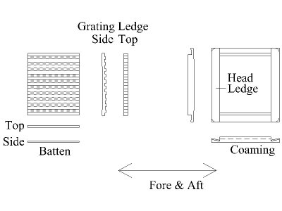
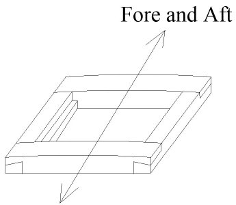
Something for the future and maybe of no concern to most but here goes, just in case..... the head ledges always sit on top of the coamings with a lap joint, not a mitered joint and the battens on the gratings always ran fore and aft. Hopefully the following sketches explain it better than my words. Note that sometimes, contemporary models show the portion of the corners that are above the level of the deck planking are rounded.
Allan


