

• Ships of Scale has incorportated an extra level of security when you log In. Please follow on-screen prompts to acknowledge that you are not a robot via a "Check Box" or a "Pictorial Check Box Puzzle". This is needed due to higher level of AI Activity Security.
  • SUBSCRIBE TO SHIPS IN SCALE TODAY!

    The beloved Ships in Scale Magazine is back and charting a new course for 2026!
    Discover new skills, new techniques, and new inspirations in every issue.

    NOTE THAT OUR NEXT ISSUE WILL BE July/August 2026
  • Win a Free Custom Engraved Brass Coin!!!
    As a way to introduce our brass coins to the community, we will raffle off a free coin during the month of August. Follow link ABOVE for instructions for entering.

IJN Pre-Dreadnought Battleship Mikasa by Merit 1:200 with Pontos and KA Models

Good morning, Paul and Chris.

First of all, thank you very much, Paul—that’s very kind of you.

Chris:
No, as far as I know, Zeiss Jena did not supply rangefinders to the Imperial Japanese Navy for the Battle of Tsushima. Instead, coincidence rangefinders from the Scottish firm Barr & Stroud are credited with the Japanese forces' superior targeting accuracy.

However, there is indeed a connection to Zeiss Jena—not involving rangefinders, but rather the admiral's binoculars: during the battle, Japanese Fleet Admiral Tōgō Heihachirō wore a famous Carl Zeiss Jena "naval turret binocular" around his neck. These binoculars were a top-tier personal instrument and can still be seen today on the museum ship *Mikasa* in Japan. Since Tōgō used them to keep the Russian fleet in sight, the Zeiss name was frequently mentioned prominently in reports.

I imagine that is how this piece of misinformation might have originated.
 
Last edited:
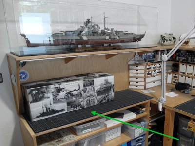
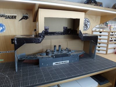
Before I can turn my attention to the masts, I have to attend to a mundane but necessary task.

The model still needs protection against dust, as it will be several weeks before I finish the *Mikasa*.

Up to now, it has been sitting under a simple, custom-cut cardboard cover. For a project spanning over two years, this is essential.

109.JPG

Now that the masts are to be installed, more vertical clearance is required. So, I got a second piece of cardboard, cut both to size, and joined them together. Everything is held in place and reinforced with duct tape.

109a.JPG

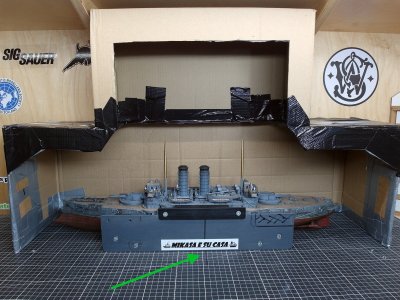
Of course, it is important to measure everything precisely beforehand—to avoid any contact between the masts and the cardboard later on. I’ve marked the positions on both the model and the tabletop using a permanent marker. This ensures the model is in the right spot when I slide the dust cover over it.

109b.JPG

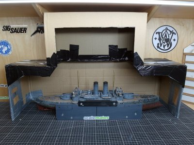
As you can see in the following picture, the ship’s layout isn't perfectly symmetrical. That explains the markings and the generous cutout in the cardboard. This way, there shouldn't be any issues once the masts are fully installed.

109c.JPG

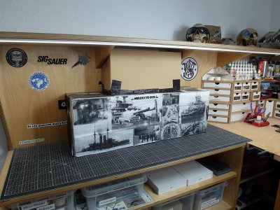
And so, I believe the model is well-protected against the looming threat of dust bunnies while it awaits completion.

109d.JPG
 
Before I can turn my attention to the masts, I have to attend to a mundane but necessary task.

The model still needs protection against dust, as it will be several weeks before I finish the *Mikasa*.

Up to now, it has been sitting under a simple, custom-cut cardboard cover. For a project spanning over two years, this is essential.

View attachment 631440

Now that the masts are to be installed, more vertical clearance is required. So, I got a second piece of cardboard, cut both to size, and joined them together. Everything is held in place and reinforced with duct tape.

View attachment 631441

Of course, it is important to measure everything precisely beforehand—to avoid any contact between the masts and the cardboard later on. I’ve marked the positions on both the model and the tabletop using a permanent marker. This ensures the model is in the right spot when I slide the dust cover over it.

View attachment 631442

As you can see in the following picture, the ship’s layout isn't perfectly symmetrical. That explains the markings and the generous cutout in the cardboard. This way, there shouldn't be any issues once the masts are fully installed.

View attachment 631443

And so, I believe the model is well-protected against the looming threat of dust bunnies while it awaits completion.

View attachment 631444
Beautiful and stunning modelling.
 
With those masts in place, she’s really starting to look like a proper pre-dreadnought. Beautiful work! Can’t wait to see her finished.
 
My dear Wieslaw, thank you. In that case, I'll go ahead and continue working on the masts.

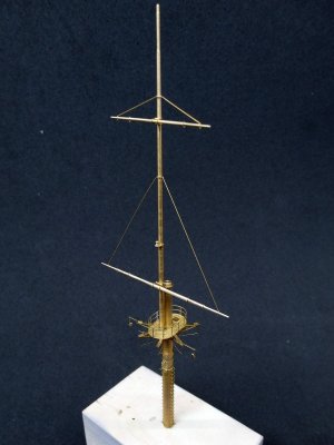
After a forced break due to illness, I can finally get moving to it. Let's start with the mainmast; it’s more complex than the foremast because the derrick boom needs to be installed on it.

Here is the first quick update.

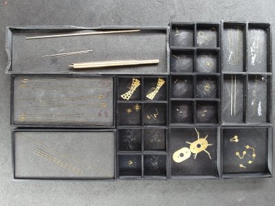
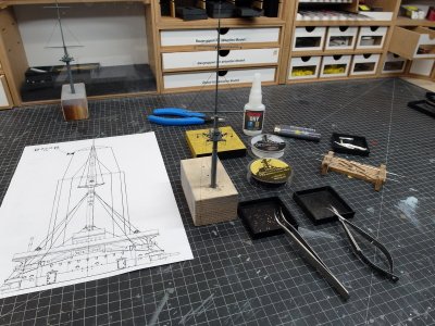
I’ve got everything prepped and laid out for the job.

109.JPG

The intricate block-and-tackle assembly—featuring those photo-etched ropes—is actually really nice, but I can't use it as-is. You might recall that I attached the derrick boom to the lower section of the mast quite a while ago. There were structural reasons for doing that, but it rules out using the photo-etched parts in their current form.

109a.JPG

So, I’ve cut everything off and am assembling the pulley blocks without the photo-etched ropes—more on that later. I’ll simply use rigging thread instead.

109b.JPG

Let's start with the base. It’s straightforward work, thanks to the perfectly fitting rings and well-designed photo-etched ladders from Pontos.

109c.JPG

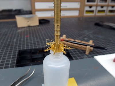
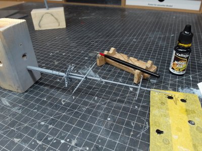
Now for the first delicate assembly step: the gusset plates beneath the platform. I put together a small jig to hold the mast upright while I attach the parts under the platform.

109d.JPG

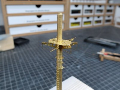
It’s already looking great. I love the level of detail Pontos provides.

109e.JPG

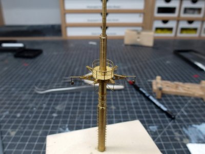
I’ve also installed the pulleys for the rudder angle indicator and the railing.

109f.JPG

And this is how the two yardarms can be threaded into place.

109g.JPG

That wraps up my quick introduction; now I can admire the fine brass component a bit more before continuing with the build today.

109h.JPG

However, I’m going to assemble the foremast to the same stage first, before the complicated part on the mainmast begins.
 
Thank you so much, wieslaw.

Here is another quick mini-update for today.

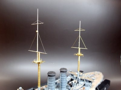
The basic structure of the foremast is essentially complete, meaning the sails could theoretically be set.

To check that everything is aligned at the correct angles, I’ve positioned the masts in their respective places.

109i.JPG

It looks really good. It gives the ship a towering profile—significantly more mast than on my *Bismarck*, for instance.

109j.JPG

Just as *Archaeopteryx* is to birds, the *Mikasa* represents the missing link for me—bridging the gap between venerable sailing ships and the modern steel behemoths of the twentieth century.

109k.JPG

Now for the finer details.
 
Here is the next quick update.
This is the last major component that is quite complex to fabricate. That’s why I share these small interim results regarding the masts; I’m usually just relieved to have finished a particular section without any major mishaps.
It almost happened a little while ago.
While I was trying to add some highlights to the chipping points, the visor of my magnifying glasses bumped into the wind vane at the top—and *snap*, it was bent. Fortunately, it stayed attached and the "carpet monster" didn't eat it.
It wasn't a huge deal to straighten it back out, but it was annoying nonetheless. You have to be incredibly vigilant with these delicate, awkward mast components.
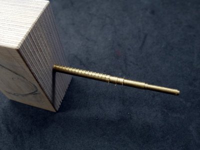
And that’s despite the fact that I mount the brass masts in a handle to make working on them easier—like here, where I’m painting the photo-etched yard ropes black.

109l.JPG

So, the base coat is applied, and they look absolutely fantastic.

109m.JPG

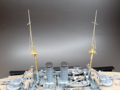
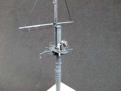
After some subsequent weathering, the basic structure of the masts is complete.

109n.JPG

The signal gaffs will be attached to the masts later, as they would only get in the way during the next assembly steps—namely, the searchlights, the sailor figures, and the backstays for the upper sections of the masts.
But that’s it for today.

109o.JPG
 
Let’s move on to the next small step.

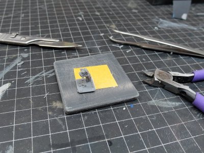
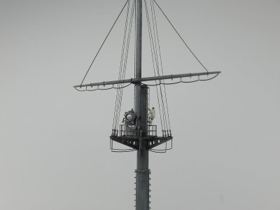
Before I can secure the upper masts with the backstays, I need to finish all other work on them. This includes mounting two of those fantastic searchlights from Micro Master onto the platforms.

To remove them cleanly from their support structure, I always tack them onto a small PVC sheet using double-sided tape. This ensures a secure hold while peeling these delicate structures away from the excess printing supports.

110.JPG

The climbing aids needed to reach the very top of the masts were still missing. According to the assembly instructions, they are supposed to be attached to the sides. I changed this for two reasons.

First, this configuration cannot be confirmed by any photograph of the *Mikasa*. However, there is an excellent, high-resolution photo of the *Azuma* showing them positioned exactly as I have them now—attached at the rear.

Second, in my opinion, the side-mounted arrangement doesn't work well with the yardarms, as the climbing aids would have to pass right by them. So, this is the solution I came up with:

110a.JPG

Then, a bit of manpower was needed—a lookout keeping a sharp eye out:

110b.JPG

A sailor climbing up:

110c.JPG

And there seems to be a problem with the searchlight:

110d.JPG

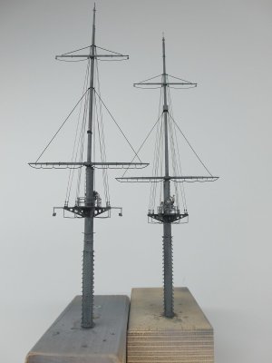
And with that, the basic assembly of the masts is complete.

110e.JPG

Tomorrow, I can install the upper backstays.

110f.JPG
 
Moving on to the masts!

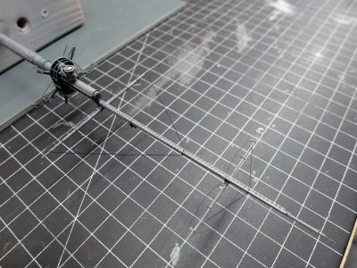
All that’s missing now are the upper backstays. This time, I’ve decided not to use the lines provided in the photo-etched parts set; instead, I’m crafting them myself using rigging thread. In my opinion, this looks more cohesive and fits better with the overall appearance.

I’ve prepared everything accordingly—repurposing some railing stanchions, which I’m using as makeshift line tensioners.

111.JPG

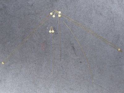
This simple solution makes the work significantly easier, and the results are well worth it. A major advantage is that I can create an entire pair of backstays using a single, continuous thread. This saves effort while ensuring a clean, neat look.

111a.JPG

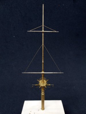
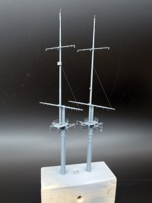
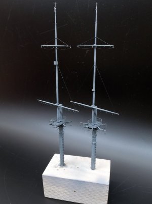
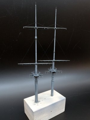
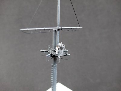
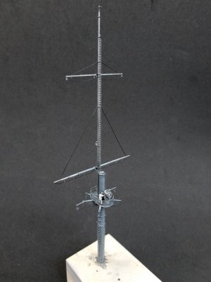
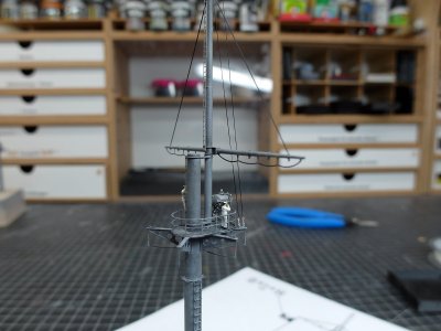
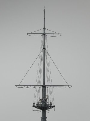
To make the rigging thread easier to see in the photos, I took the next few shots against a white background. Here you can see the foremast, now fully equipped with all twelve backstays.

111b.JPG

With that, the first mast is completely rigged—a great step forward!

111c.JPG

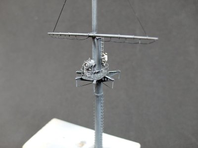
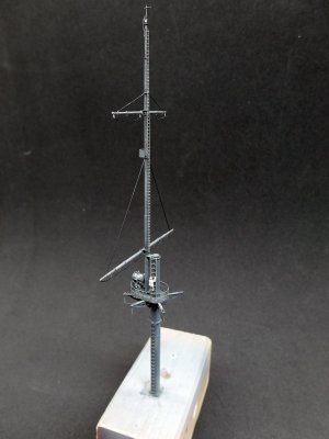
Next up: the mainmast.

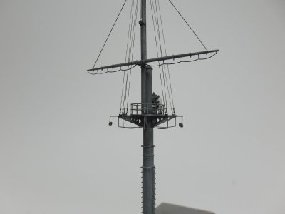
At first, I was a bit cautious when tensioning and pulling the individual lines—after all, everything needs to sit properly and look uniform in the end. But as is often the case, practice leads to routine; by the end, the work was progressing quite quickly.

111d.JPG

And before you know it, the second mast is finished, too!

111e.JPG

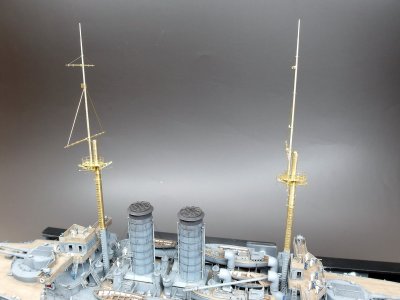
With that, the rigging for both masts is complete, and they are ready to be placed onto the model.

111f.JPG

Next on the agenda is the crane, complete with its pulley system.

Looks like another little challenge awaits! I’ll be sure to keep you posted!
 
A lovely Sunday to all my fellow ship modellers and many thanks, Peter!

For me, today has turned out to be a particularly wonderful Sunday, because I’ve managed to take a small but very satisfying step forward with my build. To be honest, when I first started thinking about it, I wasn’t entirely sure how to tackle it properly. All the more reason to be pleased with the result, and of course, I’d like to share it with you. So today, I have a very short build update for you.

But let’s take things one step at a time!

I had to come up with a solution for the tackle on the crane boom. Since I’ve made some fairly substantial changes to the original build sequence of my model, I could no longer use the photo-etched part originally intended to represent the block-and-tackle assembly. And to be perfectly honest, I’ve never been particularly keen on those flat, two-dimensional ropes represented by photo-etched parts anyway. So, I needed to find another solution!

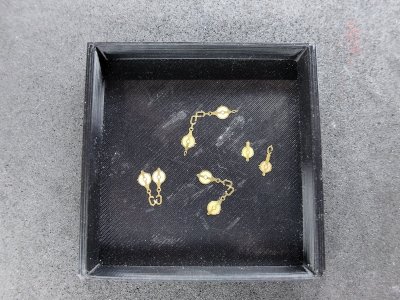
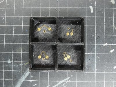
I therefore took the photo-etched parts apart and separated the blocks from the running lines.

112.JPG

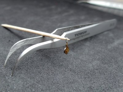
So far, so good. But now came the real challenge: making my very first block with a proper sheave of my own!

Incidentally, I hope I’m getting the terminology more or less right this time. If not, please feel free to correct me!

First, I rummaged through my old box of photo-etched parts. And lo and behold, I actually found a few suitable sheaves that were just right for what I had in mind.

Next, I dismantled the photo-etched blocks further until I had the two halves of each block separated. I then soldered a suitable sheave onto one of the halves.

112a.JPG

After that, I put the second half back in place. I also inserted a small piece of profile at the top to form the attachment point for the eye. This allowed me to solder everything together neatly without distorting the delicate little component.

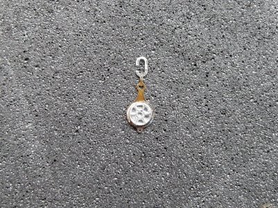
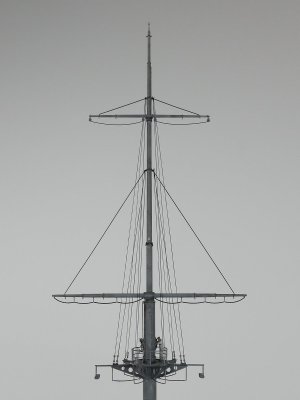
And then the moment finally arrived: my very first scratch-built block with a proper sheave was complete!
112b.JPG

I’m already really pleased with this little prototype. At last, a nice, three-dimensional sheave that actually looks the part!

112c.JPG

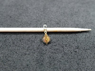
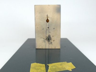
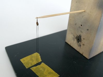
And now comes the real icing on the cake for me: I can simply reeve my rigging thread through the block. No more flat, photo-etched appearance — just a solution that looks much closer to the real thing.

112d.JPG

In theory, this means I’m now even able to make a proper tackle — or, to be more precise, a working purchase! And with my crane boom, I could actually lower one of my lovely 3D-printed pinnaces into the water, if only the boom weren’t glued firmly in place!

And all of this in 1:200 scale!

112e.JPG

What makes me particularly happy is that I haven’t simply settled for some sort of compromise. I’ve found a solution that works well both in practice and in terms of appearance.

If this isn’t a fantastic Sunday, I don’t know what is!

I wish you all a lovely and relaxing Sunday. And, as always, suggestions, tips and constructive criticism are more than welcome!
 
Back
Top