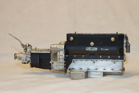
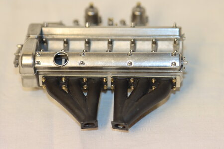
Jaguar c-type engine. 1/8 scale

Tedboat, that is really an awesome engine. I thought working on the plastic was fun but metal looks great. Are the pistons and all included? I did a couple Pocher kits with engines you could crank over but this looks even more detailed. I guess you get what you pay for. Keep up the good work

Vintage Modeler
Hi Vintagemodeler,
I'm thoroughly enjoying this build, but regrettably the 'inner workings' are not included. Wish they were!
Ted
 
Have not had much chance to get in the workshop for a couple of weeks, but have managed a little.


IMG_0206a.jpg
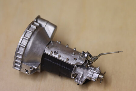
Bellhousing and gearbox

IMG_0213a.jpg
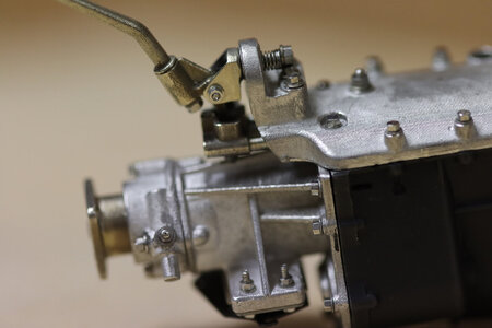
Gear selectors and gearstick. Unusually, the selectors linkage is outside the gearbox - an arrangement I would have thought was an invitation for road muck, stray nut, washers. But it worked.

IMG_0193a.jpg
Right hand side of engine block after painting. Core plugs inserted.


IMG_0194a.jpg
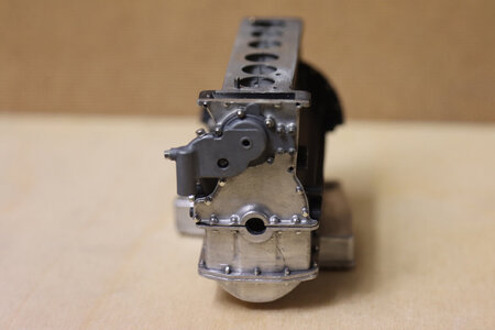
Cam chain cover bolted on. I've been a little over-enthusiastic filing out the crankshaft hole, but fortunately it will be hidden.


IMG_0167a.jpg
Crankshaft damper unit. Would be bolted onto the crankshaft if there was one, but in this case has a brass tube stub.

IMG_0219a.jpg
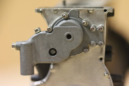
Closer view of the cam chain cver, with the water pump casting bolted on to that. The kit instructions say use bigger washers for the top two bolts, but I think I will change them for smaller ones.

All for now!
Ted
 
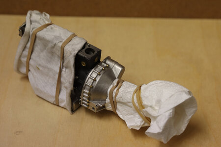
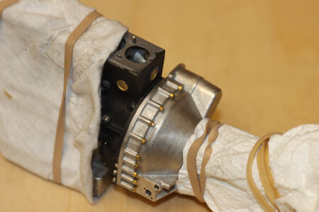
Time to unit the engine with the transmission!

IMG_0223a.jpg
Why all wrapping? - well, the engine and gearbox are partially painted matt black, which is easily scratched or marked with oil from my hands, and there is a lot of handling required when mating these two components.


IMG_0227a.jpg
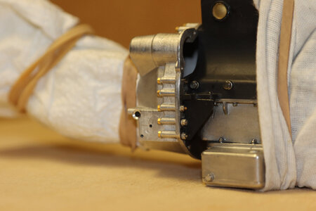
The bell housing is held on to the engine by a number of bolts and two brackets.
(Uwe, when you come to this part it is essential you use the template provided in order to make sure it all lines up. It took me about three hours to ensure I got it right!)


IMG_0231a.jpg
Right side of engine showing one of two support brackets on to the bell housing. These are a b****r to install, as the bolts holding the brackets to the engine are screwed into the crankcase on the inside of the bracket.

IMG_0245.JPG


IMG_0259a.jpg
Now comes a tale of disaster!!
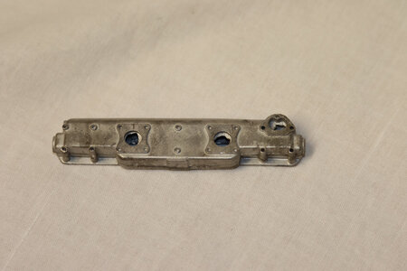
The object above is the inlet manifold, holding the carbs and directing the petrol/air mix to the cylinders (doesn't look very efficient in terms of gas flowing, but it was designed in the late 1940's!)
The manifold has two castings, inner and outer, which have to be glued together before bolting onto the engine so holes can be drilled through.
As luck would have it, the inner casting had a very slight distortion on it, so after straightening it by hand, I glued them together and decided to hold them with spring clamps until the glue dried. The next day, I found the white metal had distorted badly, to the point where it was non-repairable. Disaster!
I e-mailed Uli at Autograph models (the kit manufacturer) and told him the sorry tale. He straight-away organised for the two pieces to be cast for me, and sent them to me free of charge! Now this was a kit I had bought five years ago! How many manufacturers would have gone that far? Full marks to Autograph!

IMG_0249a.jpg
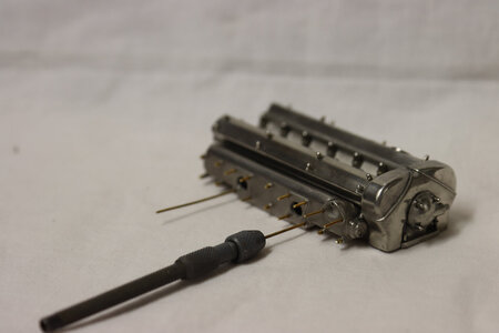
Not a good photo, but it shows the manifold in position, and the method of inserting the studs to hold it. The studs are supplied min the form of 1.0 mm threaded rod, which can be held in a pin vice and screwed in to pre-drilled holes in the crankcase before being cut off to length.

IMG_0251a.jpg
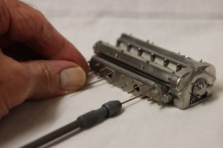
Same process, but with large hand to give an idea of scale (Incidentally, if you want to see a really large scale engine, have a look at the Pocher models Ducatti being built by Peter Voogt. Some model!)


IMG_0256a.jpg
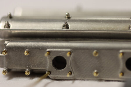
Again, not a good photo, but it shows the nuts and washers on some of the studs. The studs have still to be filed down to just above the nuts.


That's your lot for today!

Ted
 
Hi Ted,
A lot of engine details and tiny parts. It’s if I already can smell the engine oil.
And a good service of Autograph.
(Thanks for the advertising for the Duc ;-)
Regards Peter
 
Time to unit the engine with the transmission!

View attachment 186976
Why all wrapping? - well, the engine and gearbox are partially painted matt black, which is easily scratched or marked with oil from my hands, and there is a lot of handling required when mating these two components.


View attachment 186977
The bell housing is held on to the engine by a number of bolts and two brackets.
(Uwe, when you come to this part it is essential you use the template provided in order to make sure it all lines up. It took me about three hours to ensure I got it right!)


View attachment 186978
Right side of engine showing one of two support brackets on to the bell housing. These are a b****r to install, as the bolts holding the brackets to the engine are screwed into the crankcase on the inside of the bracket.

View attachment 186979


View attachment 186980
Now comes a tale of disaster!!
The object above is the inlet manifold, holding the carbs and directing the petrol/air mix to the cylinders (doesn't look very efficient in terms of gas flowing, but it was designed in the late 1940's!)
The manifold has two castings, inner and outer, which have to be glued together before bolting onto the engine so holes can be drilled through.
As luck would have it, the inner casting had a very slight distortion on it, so after straightening it by hand, I glued them together and decided to hold them with spring clamps until the glue dried. The next day, I found the white metal had distorted badly, to the point where it was non-repairable. Disaster!
I e-mailed Uli at Autograph models (the kit manufacturer) and told him the sorry tale. He straight-away organised for the two pieces to be cast for me, and sent them to me free of charge! Now this was a kit I had bought five years ago! How many manufacturers would have gone that far? Full marks to Autograph!

View attachment 186987
Not a good photo, but it shows the manifold in position, and the method of inserting the studs to hold it. The studs are supplied min the form of 1.0 mm threaded rod, which can be held in a pin vice and screwed in to pre-drilled holes in the crankcase before being cut off to length.

View attachment 186988
Same process, but with large hand to give an idea of scale (Incidentally, if you want to see a really large scale engine, have a look at the Pocher models Ducatti being built by Peter Voogt. Some model!)


View attachment 186989
Again, not a good photo, but it shows the nuts and washers on some of the studs. The studs have still to be filed down to just above the nuts.


That's your lot for today!

Ted
Lovely work once again Ted,
That is fantastic support from the manufacture, I am guessing that the finish on the rocker covers and inlet manifold are the castings after some polishing / elbow grease applied.
Cheers,
Stephen.
 
I love the metal shading, is that just the way it comes or are the parts slightly weathered? Look great in any event.Great photos also!
Hi,
The castings with the kit are merely cleaned up, with occasional pieces of flash removed, and then polished with a mildly harsh cleaning fabric supplied with the kit.

Regards

Ted
 
This one works.
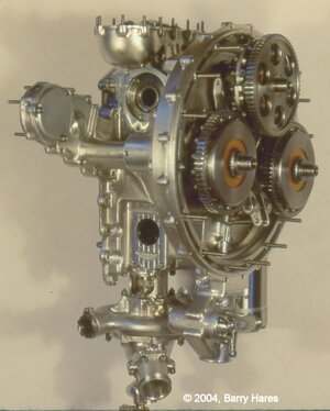
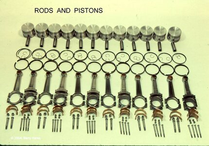
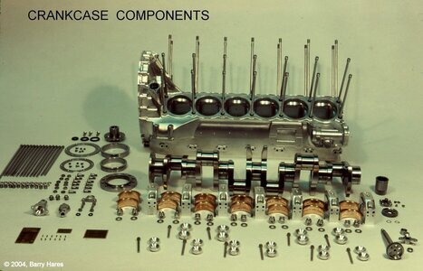
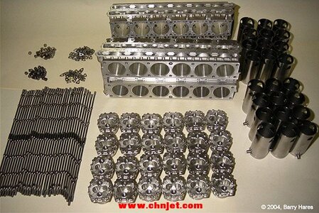
Barington Hares 1:5 RR Merlin. Scratch built.
Eat your heart out.
View attachment 187125View attachment 187126View attachment 187127
Oh, to have the skill and the workshop to be able produce something like this!
I was at the London Modelling Exhibition about twenty years ago when a rotary aero-engine to a similar scale was demonstrated. The noise was fantastic, and all other activity in the hall was instantly suspended as everyone crowded in for a look!
 
Barington Hares 1:5 RR Merlin.....that Merlin is a faithful replica, not something that just looks like a Merlin it is a Merlin, inside and out. All the more impressive, considering RR has never released the workshop drawings. S Mr Hares must have done all his own research to put all the details into his own drawings, before cutting and casting metal.
He also did the same with a RR sleeve valve 24 cylinder engine.
The mind boggles.

101940dy6det236vv22fv6.jpg
 
Thanks guys!
The SU's are rather interesting in that they have a fixed jet, unlike the 'modern' SU, where the jet moves down to enrich the mixture for starting. The arrangement here is for a supplementary carb which when activated feeds additional petrol through a separate pipe into the underside of the intake manifold. You can see it between the two carbs in my picture, to the right of the rear SU float chamber.
 
Back
Top