
My first thoughts are Great Work! And - can you not find stock that has straight grain? All that cross-grain material is just asking for problems. Straight grained wood, especially oak, bends a lot easier and better.Update 3
Yes now comes the hard stuff. The first three battens on either side still went reasonably smoothly. On the fourth, a little less so.

This batten has a slightly rounded bend at the end, (not visible here) so the grain runs diagonally across the batten, and is therefore very vulnerable.
Oak battens when dry are hard. However, if you wet them well (A few hours) they become remarkably supple and you can bend them reasonably. But not in the strong bend you need. With a hot plank bender, you can get the bend in well and also twisted. But that heating also dries the batten and hardens it again. If you then try to press the batten into place, it will break, as here.
Solution: You have to shape the batten as well as possible (with a plank bender), then wet it again (=flexible) and then press it into place and fasten it, and let it keep its shape. Then the shape will stay there. Then glue. With basswood, all that doesn't need to be so elaborate, but with oak so apparently it does.

The other side went well but then I noticed a big gap between the third and fourth batten. Now I remembered this problem with Hans too, and he solved it by putting a vise on it to better clamp the end of the battens against the stem.

So I did that too after moistening for a while, making the wood supple and bendable again. With a batten in between to prevent damage. Unfortunately, I didn't look at the other side. There is a kink there now.

Now on the other side, with a kink in truss three, see to fitting the broken batten. I first made a shim to support the small point slightly. Here of oak but balsa would have been a lot easier.

Here's the fourth and the start of the fifth batten on it. A tip is also broken from the fifth one. It is difficult to apply an entire 40 cm batten in one go. In real life, that's 25 m. In the Roman Rhine Vessel, I have built, planks 25 m long were used, but 1500 years later they are no longer to be found. During the construction of the model of the Kamper kogge, Which I build also, it became clear to me that applying an entire batten in one go is actually not a doable task and did not happen in real life.
Therefore, I divided the second fifth strakes into two by applying a joint.

Here is the first half from the stern on. That side is the most crucial for connection. On the bow side, there is some room for adjustment. Even better would be to apply in threes. Then you can connect the bow and stern neatly to the stem and fit the third piece between them appropriately.
Maybe I'll try that on the next batten.
And here is the current state of affairs.
Photos of bow, stem and overall.


I have also given some thought to possible adjustments. See below a list of what I am thinking of.
For determining these modifications, one of the things I am following is Maarten's report on ShipsOfScale. There he builds a flute from scratch but strongly based on the wreck of "The Swan" found in the Baltic Sea. See: https://shipsofscale.com/sosforums/...econstructing-the-ghost-ship-scale-1-36.9685/
The Kolderstok kit includes ornaments based on this wreck. My model will therefore also be called "De Zwaan".
Modifications to the hold
- Attaching turning frames and other frames
- Attaching spars with mast tracks
- Attaching inner "wegering" and denning
- Adding access to the hold with stairs or ladders
- Installation of lighting using LEDs as oil lamps. Including wiring throughout the ship.
- Attaching hooks/eyes for suspending hoists.
- Attaching cargo (Posts, beams, barrels)
On the ship's side
- Port side openings for inserting planks/beams
- Stern openings for inserting poles/beams
- Starboard openings for making hold visible. Dismountable
- Starboard openings for making cabin and rudder controls visible. Dismountable
On cabin.
- Furniture, wardrobe, chairs, chest.
- Lighting
- Fitting ceiling.
- Access door from rudder control room
- Mirror windows.
On the orlopdeck
- Extend structures from deck above to this deck (Pumps, betings, etc.)
- Hammocks ??
- Cargo ??
- Cables ??
- Hatches to the hold ??
When building it becomes clear what can be realised.
To be continued.

-

SUBSCRIBE TO SHIPS IN SCALE TODAY!
The beloved Ships in Scale Magazine is back and charting a new course for 2026!
Discover new skills, new techniques, and new inspirations in every issue.
NOTE THAT OUR NEXT ISSUE WILL BE MARCH/APRIL 2026 -

Win a Free Custom Engraved Brass Coin!!!
As a way to introduce our brass coins to the community, we will raffle off a free coin during the month of August. Follow link ABOVE for instructions for entering.
You are using an out of date browser. It may not display this or other websites correctly.
You should upgrade or use an alternative browser.
You should upgrade or use an alternative browser.
Kolderstok. Fluyt in oak
- Thread starter janzwart
- Start date
- Watchers 29
-
- Tags
- fluit kolderstok
Isn´t it a problem because of the preshaped laser cut planks? On one side the grain is longitudinal, but on the other side, and that you can not prevent, the grain is diagonal. Problem is with the planks, which have at their endings the curve - on both ends you have the grain direction diagonal (green area)can you not find stock that has straight grain?

But definitely oak is maybe not the best wood for ship modeling due to the rougher grain - it is often not in scale
- Joined
- Apr 10, 2020
- Messages
- 145
- Points
- 213

Uwe, You are right. Oak is not the easiest wood to use. But Dutch ships originally are mostly build in oak. Therefore some prefer to use the most original type of wood.
Therefore this build is an experiment, the very first kit of the fluyt in oak, in order of Kolderstok, who is thinking to offer this kit in oak version. Because some people want it. Kolderstok will use my experience to decide if it is doable.
Therefore this build is an experiment, the very first kit of the fluyt in oak, in order of Kolderstok, who is thinking to offer this kit in oak version. Because some people want it. Kolderstok will use my experience to decide if it is doable.
- Joined
- Jan 9, 2020
- Messages
- 10,652
- Points
- 938

Jan, I experienced the same characteristics of the oak. The only solution is to soak it, bend it with a plank bender, wet it again and then pin it to the hull to dry. Only then can you start gluing. I applied all my battens in one length on the WB, but I only glued a third of the length of the plank at a time. Also, the smaller the model, the more difficult it becomes working with oak, because the bends and curves are that much more severe. If Hans had made the Fluyt in 1:36 scale for instance, it would have helped.
- Joined
- Apr 10, 2020
- Messages
- 145
- Points
- 213
Heinrich,
That method of bending and gluing I am going to use now. I also divide the planks in two or three with a connection between. That was also from Hans a question to try. Higher on the ships hull, wher there is a lot of bending, he has already the planks divided with a connection. Only not in the bottom. Nobody will see the bottom ???
But my experience with building the cogs is that dividing a plank in three will work a lot easier.

I agree fully that oak is not the easiest wood to use, especially not for this ship. But the idea behind this is, when it works in oak, it surely will work in an more easy to bend wood like walnut.
I know Jan, I know his skills and I am sure he will do a nice and proper job on this model, but it is surely not sure this kit will become available in oak.
A difficulty which is rather problematic to overcome is the direction of the grain of the wood in combination with the laser cutting process. Fi the broken plank which Jan showed could better have been cut in a mirrored position, but that is something I cannot influence, as this is done outside our own company.
But… nice job so far Jan!
Hans
- Joined
- Apr 10, 2020
- Messages
- 145
- Points
- 213
Update 4
In my previous update, I indicated that I will name my model "The Swan" after the wreck found in the Baltic Sea. That wreck is 25 m long. My model is 47 cm over the stem and is in 1 : 72 scale. So actual length is then 33.8 m. More than longer than the real Swan. Still, it remains The Swan.
In the previous update, I also mentioned some possible modifications. To work that out better, I need a sectional diagram as shown in Hans' report, page 43, post #843. I asked Hans "Kolderstok" if he had such a diagram available because such a drawing was not in the package. According to Hans, that was by accident and he sent me such a drawing by return. Thanks for that Hans.
The main reason for such a diagram was to determine how to shape the cabin and tiller.
This is shown in the diagram below.

The thin red line is the ceiling and forward bulkhead of the cabin. The height in the cabin is then only 1.60m, see the thin green line. The tiller should therefore be straighter and higher. Also slightly higher on the rudder so that it goes slightly higher through the hen hole.
The tiller then comes out in front of the cabin in the helmsman's area which is 2m high there. So the helmsman can walk under the tiller pretty much. Not convenient to operate.
So I did some studying in the book "The Golden Age of the Flute Ship" and there I was able to deduce the following. The length in feet is 33.8 / 0.283 = 119 feet.
According to the diagram below
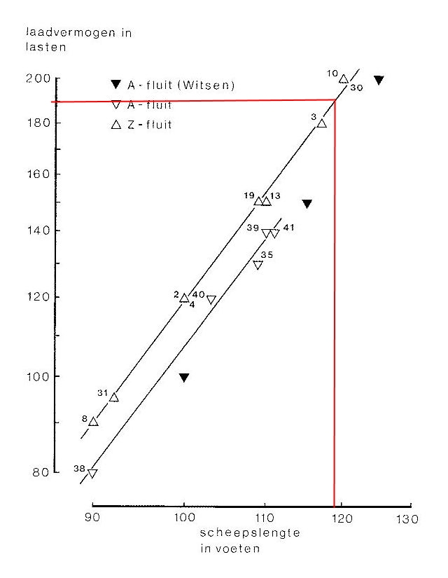
a flute of 119 feet length has a capacity of 190 "last" (=380 tonnes )
According to the following diagram:

such a ship has 22 (crew members) on board, mainly housed on the orlop-deck. The N in the diagram stands for Noordvaarders, which is this model.
The maximum length for flutes is about 130 feet. So the model is a large flute. These then generally have two decks, which is the case here.
Large flutes, like this one, which were therefore also built a bit later than the real Swan, often had a kolderstok operation and then the helmsman stood on the deck above it. So that would probably have been better here. But there was an alternative. With large flutes like this, steering could also be done by two helmsmen directly at the tiller, and then one deck lower. But with a tiller above your head like that, it is more convenient to operate it with two blocks attached to the tiller. And so that is a good solution here. The blocks are then located between the head of the tiller and the ship's wall with the fetching parts towards the amidships standing helmsmen.
To make that all a bit more visible, I am thinking of making a section of the ship's wall, as indicated by the blue line, demountable.
You can see here what that looks like longitudinally at section A:

Drawing males is not my strong point.
The deck beam at the tiller tip needs to be a bit thinner. So the blue part of the ship's wall has to be dismantled to show the interior. The forward part of the cabin will have two doors on each side. After all, you have to be able to get in. You can also see into the cabin from the side, so there will be furniture and probably lighting.

And the same edits on the foreship look like this:

Again, the blue framed part is the demountable part. The dotted squares are the cargo hatches on the other side. So that from this side it is easy to see what they are doing there. You can also just barely see onto the orlop-deck. That's where the crew accommodation is, some cargo and a cable storage. You may be able to see some of that too. So the ship walls, as they can be seen, should be finished on the inside. Note that the demountable part is within the trusses so the sturdiness is not affected.
A piece between the cargo hatches I leave without interior planking to show the trusses.
Kolderstok has drawn a horizontal line here, probably the waterline. The cargo hatches here are below that waterline, which of course can't be done. But if I raise them a little higher, they end up on the orlop-deck, which is also impossible because they have to go to the hold. So I draw the waterline on the model a bit lower. Anyone object ?
From the outside it loos like this:

So much for the theory of what it should be. Please be patient for implementation.
To be continued
In my previous update, I indicated that I will name my model "The Swan" after the wreck found in the Baltic Sea. That wreck is 25 m long. My model is 47 cm over the stem and is in 1 : 72 scale. So actual length is then 33.8 m. More than longer than the real Swan. Still, it remains The Swan.
In the previous update, I also mentioned some possible modifications. To work that out better, I need a sectional diagram as shown in Hans' report, page 43, post #843. I asked Hans "Kolderstok" if he had such a diagram available because such a drawing was not in the package. According to Hans, that was by accident and he sent me such a drawing by return. Thanks for that Hans.
The main reason for such a diagram was to determine how to shape the cabin and tiller.
This is shown in the diagram below.
The thin red line is the ceiling and forward bulkhead of the cabin. The height in the cabin is then only 1.60m, see the thin green line. The tiller should therefore be straighter and higher. Also slightly higher on the rudder so that it goes slightly higher through the hen hole.
The tiller then comes out in front of the cabin in the helmsman's area which is 2m high there. So the helmsman can walk under the tiller pretty much. Not convenient to operate.
So I did some studying in the book "The Golden Age of the Flute Ship" and there I was able to deduce the following. The length in feet is 33.8 / 0.283 = 119 feet.
According to the diagram below
a flute of 119 feet length has a capacity of 190 "last" (=380 tonnes )
According to the following diagram:
such a ship has 22 (crew members) on board, mainly housed on the orlop-deck. The N in the diagram stands for Noordvaarders, which is this model.
The maximum length for flutes is about 130 feet. So the model is a large flute. These then generally have two decks, which is the case here.
Large flutes, like this one, which were therefore also built a bit later than the real Swan, often had a kolderstok operation and then the helmsman stood on the deck above it. So that would probably have been better here. But there was an alternative. With large flutes like this, steering could also be done by two helmsmen directly at the tiller, and then one deck lower. But with a tiller above your head like that, it is more convenient to operate it with two blocks attached to the tiller. And so that is a good solution here. The blocks are then located between the head of the tiller and the ship's wall with the fetching parts towards the amidships standing helmsmen.
To make that all a bit more visible, I am thinking of making a section of the ship's wall, as indicated by the blue line, demountable.
You can see here what that looks like longitudinally at section A:
Drawing males is not my strong point.
The deck beam at the tiller tip needs to be a bit thinner. So the blue part of the ship's wall has to be dismantled to show the interior. The forward part of the cabin will have two doors on each side. After all, you have to be able to get in. You can also see into the cabin from the side, so there will be furniture and probably lighting.
And the same edits on the foreship look like this:
Again, the blue framed part is the demountable part. The dotted squares are the cargo hatches on the other side. So that from this side it is easy to see what they are doing there. You can also just barely see onto the orlop-deck. That's where the crew accommodation is, some cargo and a cable storage. You may be able to see some of that too. So the ship walls, as they can be seen, should be finished on the inside. Note that the demountable part is within the trusses so the sturdiness is not affected.
A piece between the cargo hatches I leave without interior planking to show the trusses.
Kolderstok has drawn a horizontal line here, probably the waterline. The cargo hatches here are below that waterline, which of course can't be done. But if I raise them a little higher, they end up on the orlop-deck, which is also impossible because they have to go to the hold. So I draw the waterline on the model a bit lower. Anyone object ?
From the outside it loos like this:
So much for the theory of what it should be. Please be patient for implementation.
To be continued
Last edited:
A very interesting approach, Jan. Special the demountabel parts in such a curved hull and in oak. I am sure we will be patient, we won’t hurry you.Update 4
In my previous update, I indicated that I will name my model "The Swan" after the wreck found in the Baltic Sea. That wreck is 25 m long. My model is 47 cm over the stem and is in 1 : 72 scale. So actual length is then 33.8 m. More than longer than the real Swan. Still, it remains The Swan.
In the previous update, I also mentioned some possible modifications. To work that out better, I need a sectional diagram as shown in Hans' report, page 43, post #843. I asked Hans "Kolderstok" if he had such a diagram available because such a drawing was not in the package. According to Hans, that was by accident and he sent me such a drawing by return. Thanks for that Hans.
The main reason for such a diagram was to determine how to shape the cabin and tiller.
This is shown in the diagram below.

The thin red line is the ceiling and forward bulkhead of the cabin. The height in the cabin is then only 1.60m, see the thin green line. The tiller should therefore be straighter and higher. Also slightly higher on the rudder so that it goes slightly higher through the hen hole.
The tiller then comes out in front of the cabin in the helmsman's area which is 2m high there. So the helmsman can walk under the tiller pretty much. Not convenient to operate.
So I did some studying in the book "The Golden Age of the Flute Ship" and there I was able to deduce the following. The length in feet is 33.8 / 0.283 = 119 feet.
According to the diagram below

a flute of 119 feet length has a capacity of 190 "last" (=380 tonnes )
w:w:model-building-flute-1-10-03-Eters-load-capacity.jpg
According to the following diagram:

such a ship has 22 (crew members) on board, mainly housed on the orlop-deck. The N in the diagram stands for Noordvaarders, which is this model.
The maximum length for flutes is about 130 feet. So the model is a large flute. These then generally have two decks, which is the case here.
Large flutes, like this one, which were therefore also built a bit later than the real Swan, often had a kolderstok operation and then the helmsman stood on the deck above it. So that would probably have been better here. But there was an alternative. With large flutes like this, steering could also be done by two helmsmen directly at the tiller, and then one deck lower. But with a tiller above your head like that, it is more convenient to operate it with two blocks attached to the tiller. And so that is a good solution here. The blocks are then located between the head of the tiller and the ship's wall with the fetching parts towards the amidships standing helmsmen.
To make that all a bit more visible, I am thinking of making a section of the ship's wall, as indicated by the blue line, demountable.
You can see here what that looks like longitudinally at section A:

Drawing males is not my strong point.
The deck beam at the tiller tip needs to be a bit thinner. So the blue part of the ship's wall has to be dismantled to show the interior. The forward part of the cabin will have two doors on each side. After all, you have to be able to get in. You can also see into the cabin from the side, so there will be furniture and probably lighting.

And the same edits on the foreship look like this:

Again, the blue framed part is the demountable part. The dotted squares are the cargo hatches on the other side. So that from this side it is easy to see what they are doing there. You can also just barely see onto the orlop-deck. That's where the crew accommodation is, some cargo and a cable storage. You may be able to see some of that too. So the ship walls, as they can be seen, should be finished on the inside. Note that the demountable part is within the trusses so the sturdiness is not affected.
A piece between the cargo hatches I leave without interior planking to show the trusses.
Kolderstok has drawn a horizontal line here, probably the waterline. The cargo hatches here are below that waterline, which of course can't be done. But if I raise them a little higher, they end up on the orlop-deck, which is also impossible because they have to go to the hold. So I draw the waterline on the model a bit lower. Anyone object ?
From the outside it loos like this:

So much for the theory of what it should be. Please be patient for implementation.
To be continued
Translated with www.DeepL.com/Translator (free version)
")
Regards, Peter
The horizontal line is meant as indication how high the harpuis (the off-white painted part of the hull) must be applied. It surely does not mean that the ship was lying that deep in the water. To my opinion there is room for improvisation here.
Good and interesting approach
you wrote and show
Again, the blue framed part is the demountable part.
Are you plan to make the openings really rectangle?
Would it not easier, from technical execution, and also maybe for the eye more pleasant, when the "cutting line" would follow the planking joints?
you wrote and show
Again, the blue framed part is the demountable part.
Are you plan to make the openings really rectangle?
Would it not easier, from technical execution, and also maybe for the eye more pleasant, when the "cutting line" would follow the planking joints?
- Joined
- Apr 10, 2020
- Messages
- 145
- Points
- 213
Yes I follow the planks. But I am not so good with photoshop to draw a nice curved line. Drawing a straight line is easier. And the opening midships is almost rectangular. At after ship is much more a trapezium, also there it will follow the planking.
- Joined
- Sep 3, 2021
- Messages
- 5,209
- Points
- 738
Very interesting, Jan, this opening-up also gives you ample opportunities to add countless details to the ship's interior.
This build will be a little bit of a hybrid, isn't it? Major part plank-on-bulkhead and the visible areas plank-on-frame? Very challenging build!
This build will be a little bit of a hybrid, isn't it? Major part plank-on-bulkhead and the visible areas plank-on-frame? Very challenging build!
- Joined
- Apr 10, 2020
- Messages
- 145
- Points
- 213
Update 5
It's time for another update, and now real construction progress.
Two updates back I had progressed to 5 strakes, and now there are 9 on either side. And it looks like this.

That not everything is flawless can be seen from the following images.

Here you can see that the bow is not flawless. I didn't get the bottom planks all rigid against each other. But with some sawdust mixed with wood glue, it is now tight. I noticed too late that the first plank that is horizontal against the bow is not exactly flush with the one on the other side. But this has been corrected with the second plank.
Not everything is flawless at the stern either.

Here you can see that two strakes do not quite fall into the rebate. I can think of two reasons for this. The board is completely laser cut with one laser cut joint. Now if you sand the end rafters at less of an angle as the kit builder did, your circumference from stem to stem is slightly longer so the plank is too short. Also, you can have the bulge at the stem slightly more convex than the kit builder did which also leads to slightly longer circumference. And thus to too short planks. In the previous update, I mentioned that I am going to divide the plank into three. I've done that a few times here and it works a lot easier. Only this does not solve the length problem, because everything is lasered to a fixed length. In consultation with the kit builder, he is probably going to offer the battens at least in threes with a little over-length, so that the length can be adjusted.
Hans, the first builder, with lime planks did not mention anything about this in his report. So apparently he chamfered the rafters more than I did.

So this length problem also leads to open joints.
And yes, there is still a gap somewhere. I'm going to try to close it first by wetting the board and the seam well to soften the glue and then put a clamp on it.

I have taped off the seam where there should be an opening later so the boards won't be glued together there.

And that there is still a lot of sanding to be done here and there is clearly visible here.
In short, we are well under way.
To be continued
It's time for another update, and now real construction progress.
Two updates back I had progressed to 5 strakes, and now there are 9 on either side. And it looks like this.
That not everything is flawless can be seen from the following images.
Here you can see that the bow is not flawless. I didn't get the bottom planks all rigid against each other. But with some sawdust mixed with wood glue, it is now tight. I noticed too late that the first plank that is horizontal against the bow is not exactly flush with the one on the other side. But this has been corrected with the second plank.
Not everything is flawless at the stern either.
Here you can see that two strakes do not quite fall into the rebate. I can think of two reasons for this. The board is completely laser cut with one laser cut joint. Now if you sand the end rafters at less of an angle as the kit builder did, your circumference from stem to stem is slightly longer so the plank is too short. Also, you can have the bulge at the stem slightly more convex than the kit builder did which also leads to slightly longer circumference. And thus to too short planks. In the previous update, I mentioned that I am going to divide the plank into three. I've done that a few times here and it works a lot easier. Only this does not solve the length problem, because everything is lasered to a fixed length. In consultation with the kit builder, he is probably going to offer the battens at least in threes with a little over-length, so that the length can be adjusted.
Hans, the first builder, with lime planks did not mention anything about this in his report. So apparently he chamfered the rafters more than I did.
So this length problem also leads to open joints.
And yes, there is still a gap somewhere. I'm going to try to close it first by wetting the board and the seam well to soften the glue and then put a clamp on it.
I have taped off the seam where there should be an opening later so the boards won't be glued together there.
And that there is still a lot of sanding to be done here and there is clearly visible here.
In short, we are well under way.
To be continued
Last edited:
- Joined
- Apr 10, 2020
- Messages
- 145
- Points
- 213
Update 6
We continued planking and got as far as the MDF struts could go.
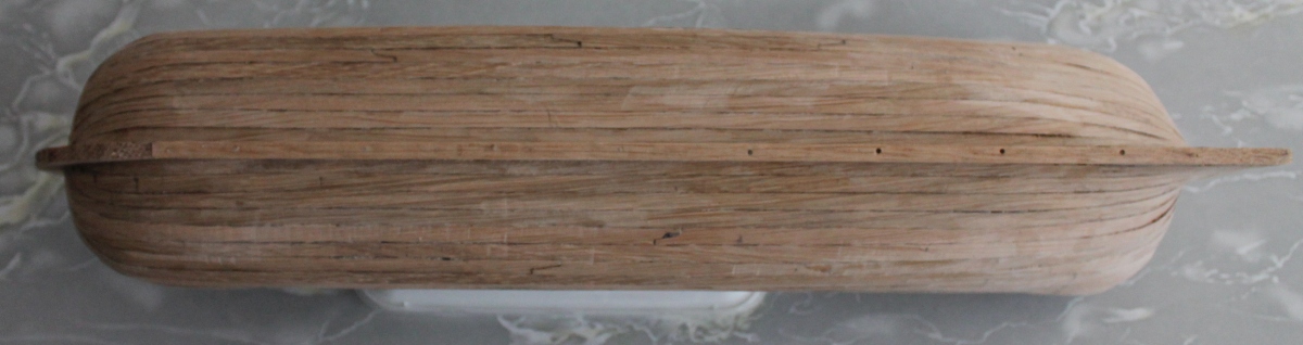
The bottom now looks like this:

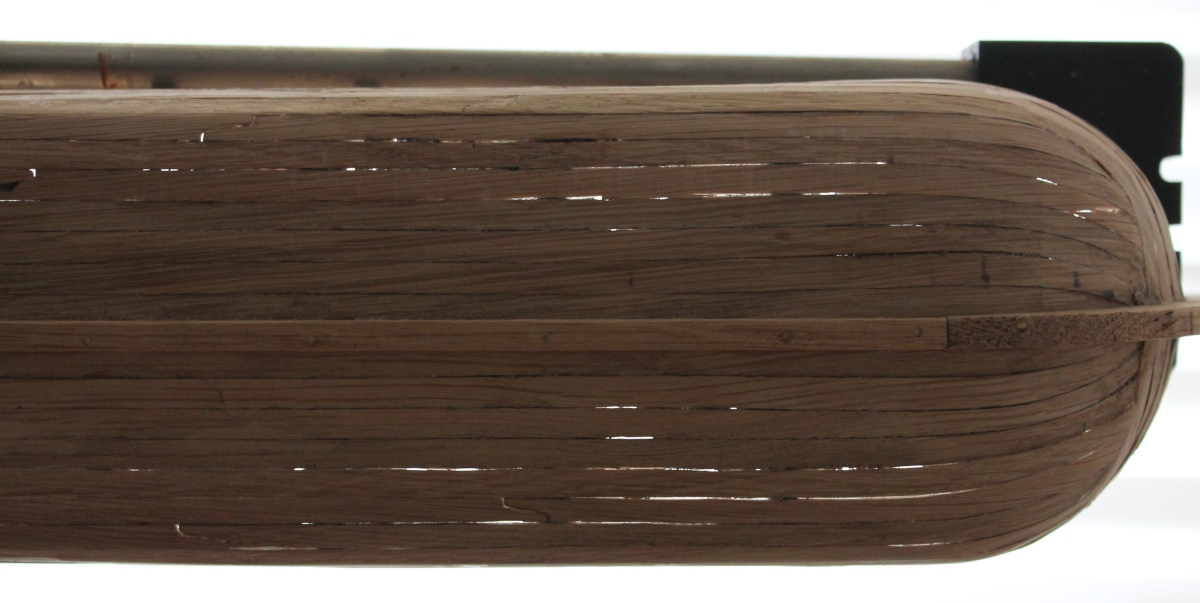
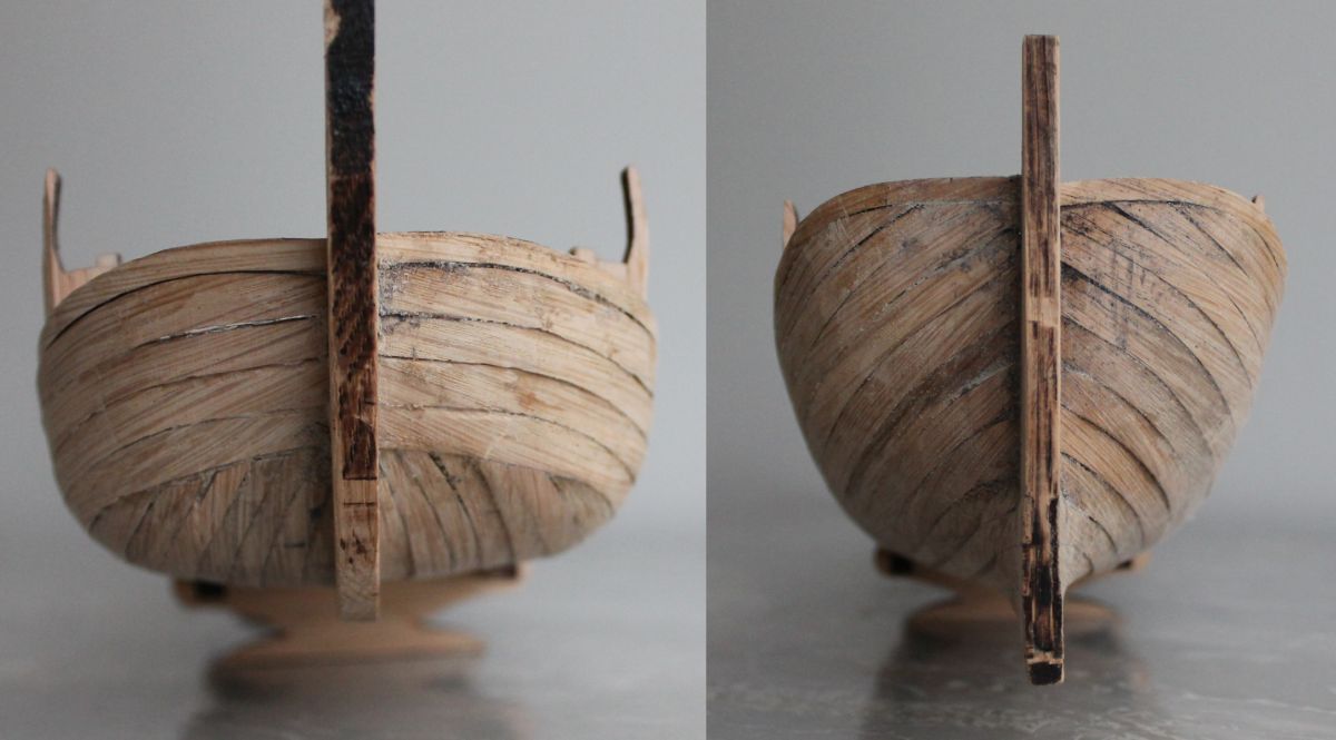
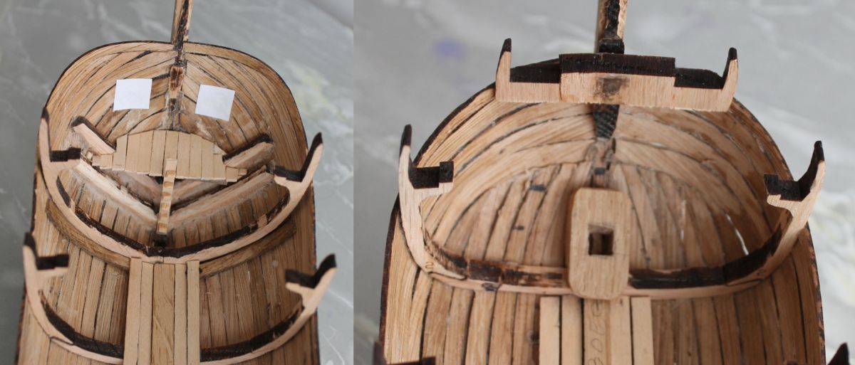
And the two stem ends like this:

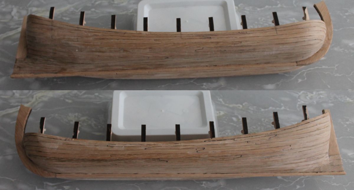
And these are the two sides:

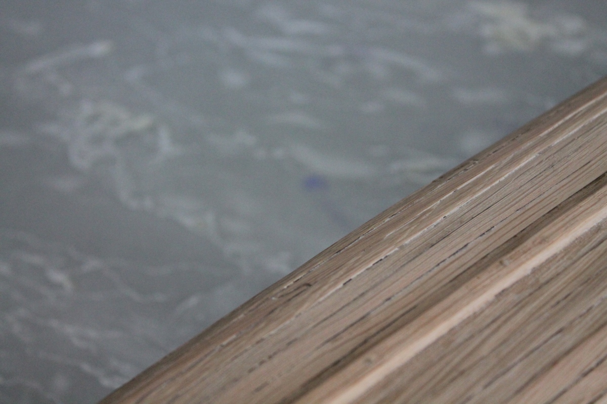
When you hold the whole thing up to the light, you see a ship you shouldn't sit in if you don't want to get wet. Fortunately, I'm not turning it into a sailing model.
I'm not going to do anything about this for now, from the outside you can see it. If it becomes visible with painting we'll see then.
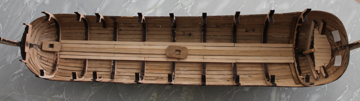
And on the inside it looks like this:

On the rear two squares have been glued indicating the place where there should be two loading hatches. Furthermore, the spar is also in place and to the side of it two bottom planks.
Both mast tracks are still loose.
There will be four loading hatches. Two in the stern and two on the port side. If they are now loading logs hanging in the hoists, I think they will also have people inside to guide things. If you are then on the bottom and can hardly see anything to the outside, I don't think that's useful. So I imagine you want to stand right behind the hatch and be able to communicate with the people outside. Either a small platform under the loading hatches that you can stand on and look outside would be handy. So I made a small platform against the rear just below the cargo hatches with a climbing pole from the bottom.

On the left, the stern with a little platform under the loading hatches. On the right, the bow with the mast track for the jib mast. That's where the turning trusses will be.
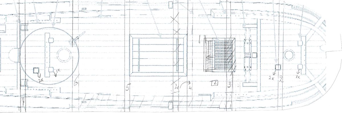
To get a good idea now of what to build on top later, I scanned the deck plan from the building description and printed it out in 1:1 scale with the model. Then I can put it on the model and see what needs to be built higher up.

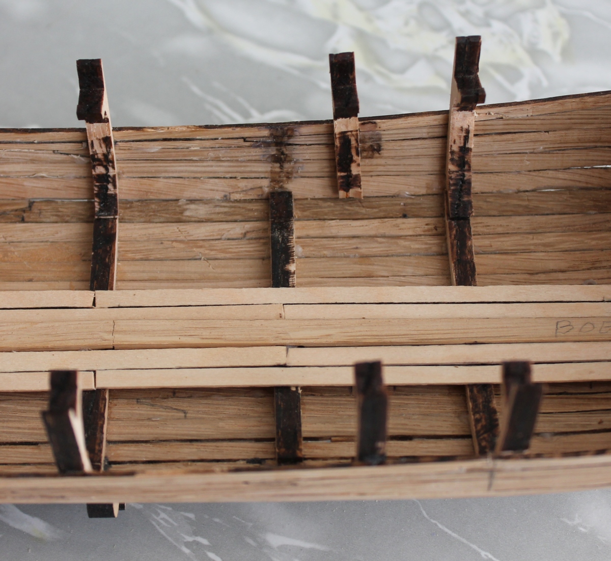
Then I see that one of the lower layer deck beams with corresponding truss no 04, runs exactly under the large deck hatch. I want to leave both hatches open so that beam has to go a bit to the side.

This truss consists of three parts, the two upright parts of which I have detached and moved a bit. Through the head of the row of trusses I put a batten to determine the correct height of the relocated truss. Otherwise, I will have problems later when laying the deck.
On the heads of those trusses, deck beams will be laid for support of the deck. But I also need those deck beams to hang some lanterns (yellow LEDs) and a whole bunch of eyes for hoists.
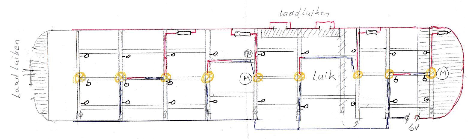
So I made a new deck plan.

Here you can see that deck beam 4 has been moved slightly forward so that the hatch is now clear. A little platform has also been drawn under the cargo hatches on the port side as well as in the bow. That will be a platform for some cargo. You can also see the locations of the yellow LEDs that will be supplied with 6 volts. The connector for this is at the bottom right.
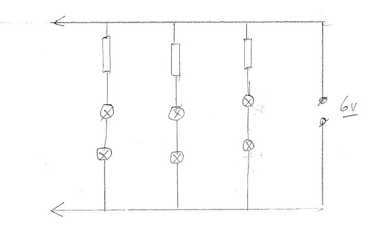
The principle diagram for the LEDs is the following:

Two LEDs in series with a resistor and that several times between the + and - of the power supply.
So there is a direct connection between the LEDs. On the deck plan, you can see that there is thus a direct wire running between the LEDs on different deck beams. That is why I am also making longitudinal beams between the deck beams where I can then hide the wiring behind. At the mast and hatch, I can only fit two elsewhere three.
There will also be double planking for the most part and I can also fit some wiring there.
To be continued.
We continued planking and got as far as the MDF struts could go.
The bottom now looks like this:
And the two stem ends like this:
And these are the two sides:
When you hold the whole thing up to the light, you see a ship you shouldn't sit in if you don't want to get wet. Fortunately, I'm not turning it into a sailing model.
I'm not going to do anything about this for now, from the outside you can see it. If it becomes visible with painting we'll see then.
And on the inside it looks like this:
On the rear two squares have been glued indicating the place where there should be two loading hatches. Furthermore, the spar is also in place and to the side of it two bottom planks.
Both mast tracks are still loose.
There will be four loading hatches. Two in the stern and two on the port side. If they are now loading logs hanging in the hoists, I think they will also have people inside to guide things. If you are then on the bottom and can hardly see anything to the outside, I don't think that's useful. So I imagine you want to stand right behind the hatch and be able to communicate with the people outside. Either a small platform under the loading hatches that you can stand on and look outside would be handy. So I made a small platform against the rear just below the cargo hatches with a climbing pole from the bottom.
On the left, the stern with a little platform under the loading hatches. On the right, the bow with the mast track for the jib mast. That's where the turning trusses will be.
To get a good idea now of what to build on top later, I scanned the deck plan from the building description and printed it out in 1:1 scale with the model. Then I can put it on the model and see what needs to be built higher up.
Then I see that one of the lower layer deck beams with corresponding truss no 04, runs exactly under the large deck hatch. I want to leave both hatches open so that beam has to go a bit to the side.
This truss consists of three parts, the two upright parts of which I have detached and moved a bit. Through the head of the row of trusses I put a batten to determine the correct height of the relocated truss. Otherwise, I will have problems later when laying the deck.
On the heads of those trusses, deck beams will be laid for support of the deck. But I also need those deck beams to hang some lanterns (yellow LEDs) and a whole bunch of eyes for hoists.
So I made a new deck plan.
Here you can see that deck beam 4 has been moved slightly forward so that the hatch is now clear. A little platform has also been drawn under the cargo hatches on the port side as well as in the bow. That will be a platform for some cargo. You can also see the locations of the yellow LEDs that will be supplied with 6 volts. The connector for this is at the bottom right.
The principle diagram for the LEDs is the following:
Two LEDs in series with a resistor and that several times between the + and - of the power supply.
So there is a direct connection between the LEDs. On the deck plan, you can see that there is thus a direct wire running between the LEDs on different deck beams. That is why I am also making longitudinal beams between the deck beams where I can then hide the wiring behind. At the mast and hatch, I can only fit two elsewhere three.
There will also be double planking for the most part and I can also fit some wiring there.
To be continued.
Last edited:
Lot of caulking to do, Jan!
Good morning Jan. This looks like a difficult build. After following Heinrich’s build I am in admiration of you guys who build a model in oak. A challenging wood for sure. Does look beautiful though . Just a thought from someone who has never put LED lights in a ship. Will the light not shine through the hull if it is not sealed perfectly? Great work on your Fluyt. Cheers GrantUpdate 6
We continued planking and got as far as the MDF struts could go.
The bottom now looks like this:
And the two stem ends like this:
And these are the two sides:
When you hold the whole thing up to the light, you see a ship you shouldn't sit in if you don't want to get wet. Fortunately, I'm not turning it into a sailing model.
I'm not going to do anything about this for now, from the outside you can see it. If it becomes visible with painting we'll see then.
And on the inside it looks like this:
On the rear two squares have been glued indicating the place where there should be two loading hatches. Furthermore, the spar is also in place and to the side of it two bottom planks.
Both mast tracks are still loose.
There will be four loading hatches. Two in the stern and two on the port side. If they are now loading logs hanging in the hoists, I think they will also have people inside to guide things. If you are then on the bottom and can hardly see anything to the outside, I don't think that's useful. So I imagine you want to stand right behind the hatch and be able to communicate with the people outside. Either a small platform under the loading hatches that you can stand on and look outside would be handy. So I made a small platform against the rear just below the cargo hatches with a climbing pole from the bottom.
On the left, the stern with a little platform under the loading hatches. On the right, the bow with the mast track for the jib mast. That's where the turning trusses will be.
To get a good idea now of what to build on top later, I scanned the deck plan from the building description and printed it out in 1:1 scale with the model. Then I can put it on the model and see what needs to be built higher up.
Then I see that one of the lower layer deck beams with corresponding truss no 04, runs exactly under the large deck hatch. I want to leave both hatches open so that beam has to go a bit to the side.
This truss consists of three parts, the two upright parts of which I have detached and moved a bit. Through the head of the row of trusses I put a batten to determine the correct height of the relocated truss. Otherwise, I will have problems later when laying the deck.
On the heads of those trusses, deck beams will be laid for support of the deck. But I also need those deck beams to hang some lanterns (yellow LEDs) and a whole bunch of eyes for hoists.
So I made a new deck plan.
Here you can see that deck beam 4 has been moved slightly forward so that the hatch is now clear. A little platform has also been drawn under the cargo hatches on the port side as well as in the bow. That will be a platform for some cargo. You can also see the locations of the yellow LEDs that will be supplied with 6 volts. The connector for this is at the bottom right.
The principle diagram for the LEDs is the following:
Two LEDs in series with a resistor and that several times between the + and - of the power supply.
So there is a direct connection between the LEDs. On the deck plan, you can see that there is thus a direct wire running between the LEDs on different deck beams. That is why I am also making longitudinal beams between the deck beams where I can then hide the wiring behind. At the mast and hatch, I can only fit two elsewhere three.
There will also be double planking for the most part and I can also fit some wiring there.
To be continued.
Translated with www.DeepL.com/Translator (free version)